Your browser does not fully support modern features. Please upgrade for a smoother experience.
Please note this is a comparison between Version 2 by Vicky Zhou and Version 1 by Saburo Matsubara.
Endoscopic ultrasound-guided hepaticogastrostomy (EUS-HGS) is widely performed worldwide for various benign and malignant biliary diseases in cases of difficult or unsuccessful endoscopic transpapillary cholangiopancreatography (ERCP). Furthermore, its applicability as primary drainage has also been reported. Although recent advances in EUS systems and equipment have made EUS-HGS easier and safer, the risk of serious adverse events such as bile leak and stent migration still exists. Physicians and assistants need not only sufficient skills and experience in ERCP-related procedures and basic EUS-related procedures such as fine needle aspiration and pancreatic fluid collection drainage, but also knowledge and techniques specific to EUS-HGS.
- hepaticogastrostomy
- endoscopic ultrasound
- endoscopic ultrasound-guided biliary drainage (EUS-BD)
- endoscopic ultrasound-guided hepaticogastrostomy (EUS-HGS)
1. Introduction
Endoscopic ultrasound-guided biliary drainage (EUS-BD) has become a promising alternative to percutaneous transhepatic biliary drainage (PTBD) after difficult or failed endoscopic retrograde cholangiopancreatography (ERCP) in patients with benign or malignant biliary obstruction [1,2,3,4][1][2][3][4]. Furthermore, its applicability as a primary drainage has also been reported [5,6,7][5][6][7]. The technique of EUS-BD is divided into rendezvous with ERCP, antegrade stenting, and bilioenterostomy, which includes EUS-guided hepaticogastrostomy (EUS-HGS) and EUS-guided choledochoduodenostomy (EUS-CDS) [8]. Among these techniques, EUS-HGS has the broadest indications, including duodenal stenosis [9], surgically altered anatomy [10], high-grade hilar stenosis [11,12][11][12] as well as failed biliary cannulation, and is therefore considered to be the most frequently performed technique in EUS-BD [13,14][13][14]. However, EUS-HGS can cause serious adverse events such as bleeding [15], bile leak leading to peritonitis or biloma/abscess, perforation, focal cholangitis, and stent migration [16].
2. Step-by-Step Tutorial on EUS-HGS Procedure including Devise Selection
In EUS-HGS, the left lateral branch of the intrahepatic bile duct is first punctured from the stomach or jejunum (in the case of post-gastrectomy) with an fine needle aspiration (FNA) needle, followed by injection of contrast medium and insertion of a guidewire. After the needle is removed, a dilation device is inserted into the bile duct to dilate the tract. Next, an introducer of a SEMSself-expandable metal stent (SEMS) or plastic stent (PS) is inserted into the bile duct. Finally, a stent is deployed between the bile duct and the stomach or jejunum (Figure 1).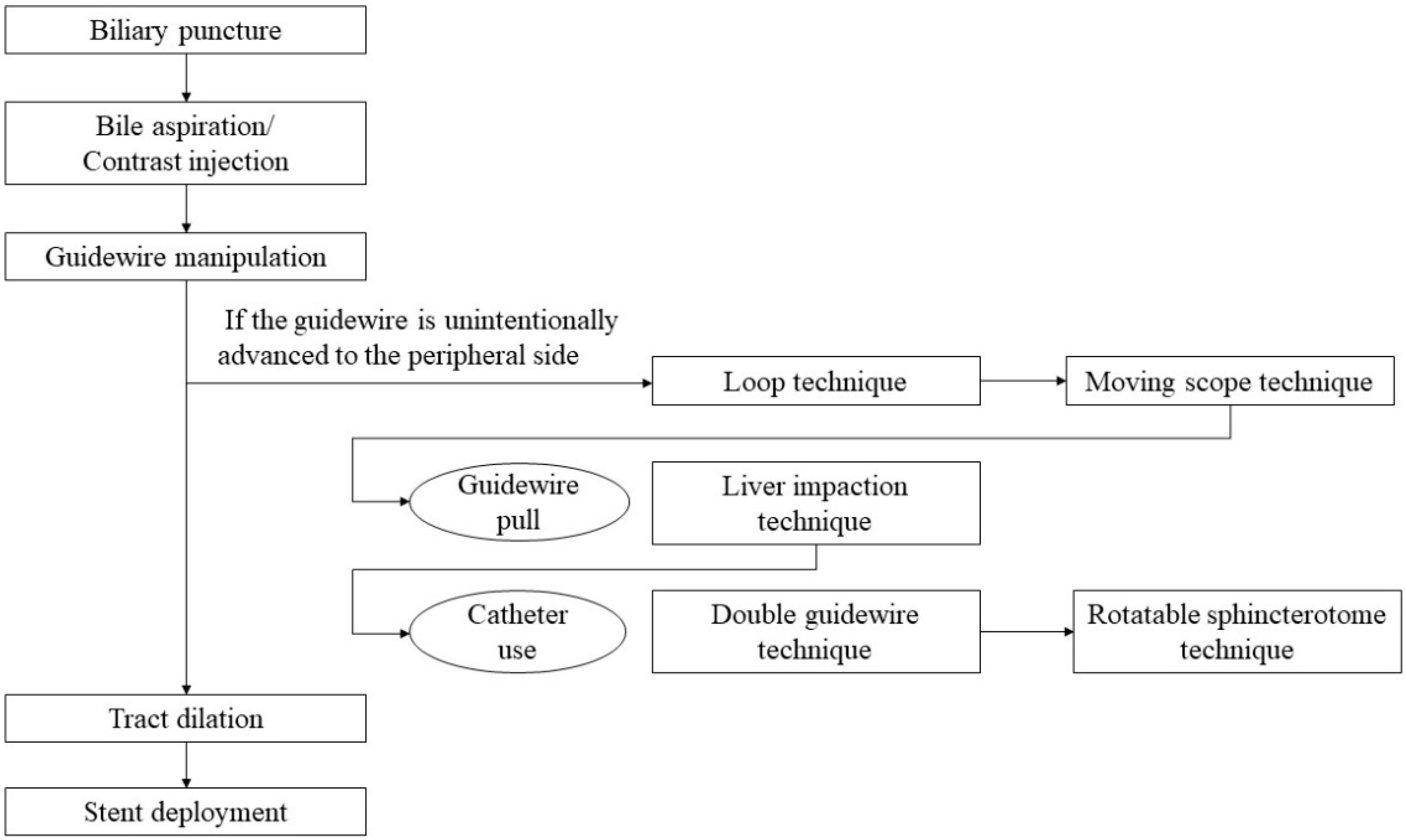
Figure 1. A flow diagram of step-by-step procedures in EUS-HGS.
2.1. Selection of Bile Duct Puncture Site and Scope Position
The intrahepatic bile ducts (B2 or B3) in the left lateral lobe of the liver are candidates for the puncture. On EUS imaging, B2 is directed from the B2/B3 junction to the right superiorly, and B3 is directed to the left superiorly [24][17]. Therefore, the B2 puncture is easier for inserting the guidewire into the bile duct because the trajectory of the needle and the direction of the bile duct are similar. However, most experts prefer to puncture B3 rather than B2 because puncturing B2 can be a transesophageal puncture, which may result in the risk of mediastinitis [8,25][8][18]. Because the position of the segment 2 of the liver is more cephalad than the segment 3, the position of the scope when puncturing B2 is shallower than that of B3, and even if the transducer is in the stomach, the exit of the accessory channel is often in the esophagus.
Before starting B3 puncture, it is desirable to adjust the position of the scope and the direction of the needle. For easy and reliable manipulation of the guidewire toward the hilum, the angle formed by the needle and the bile duct on the hilar side should be obtuse. When the scope is in a shallow position, that angle is often acute, making it difficult to manipulate the guidewire toward the hilum (Figure 2A,B); pushing the scope while turning the large wheel upward rotates the EUS image clockwise and makes that angle obtuse (Figure 3A,B). In fact, Ogura et al. reported in a retrospective multivariate analysis that strongly applying the up-angle of the scope to make the angle between the scope and the needle less than 135 degrees was a positive predictive factor of successful guidewire manipulation toward the hilum [26][19]. However, this bent scope shape reduces the forward push force during device insertion, and in the worst case, the scope may be pushed back, and the guidewire may be dislodged from the bile duct. Shiomi et al. [27][20] and Nakai et al. [28][21] reported the usefulness of the “Double guidewire technique” using a double lumen catheter (Uneven Double Lumen Cannula [UDLC]; Piolax Medical Device, Kanagawa, Japan), which allows a second 0.035 inch guidewire to be inserted adjacent to the first 0.025 inch guidewire (Figure 4).
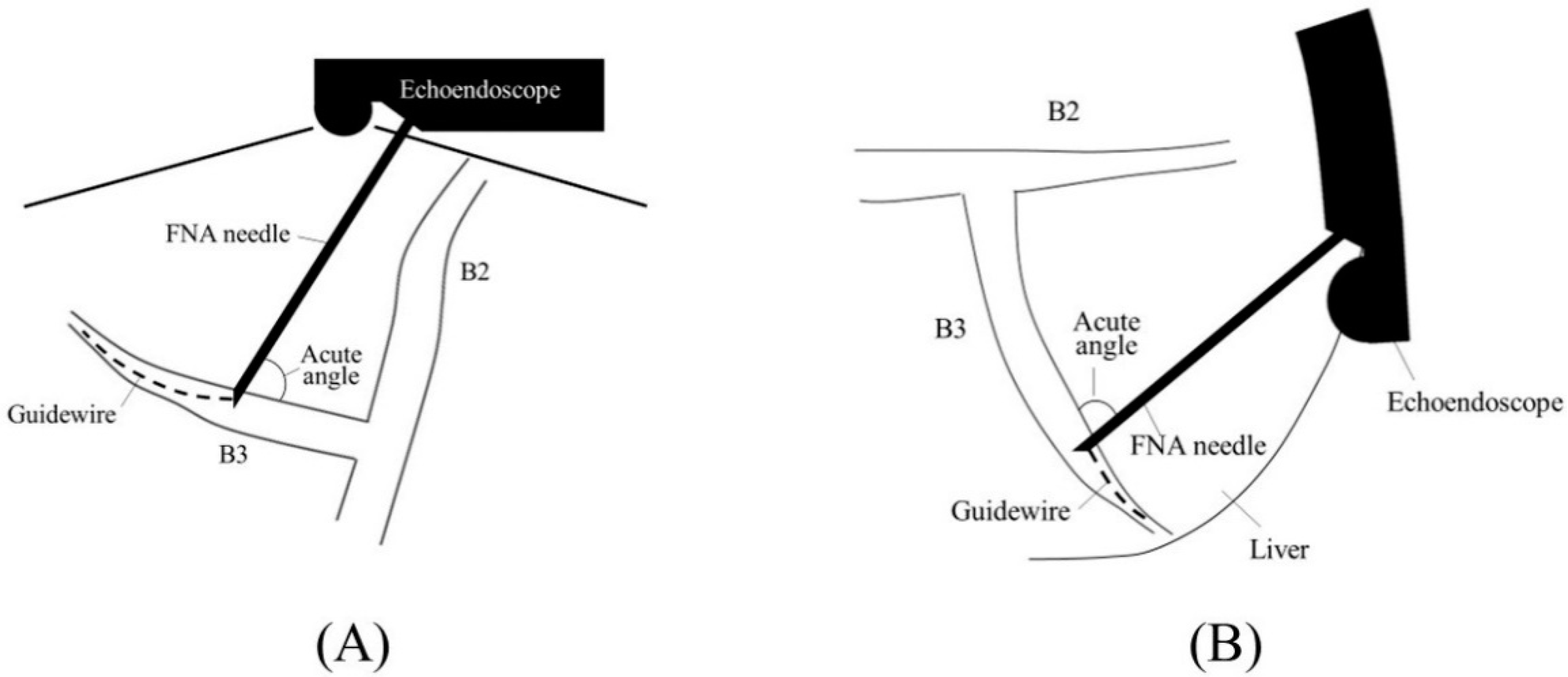
Figure 2. Too shallow echoendoscope position in B3 puncture. In a shallow scope position, the angle formed by a needle and the bile duct on the hilar side is often acute, and a guidewire can easily go to the peripheral side ((A); ultrasound image, (B); fluoroscopic image).
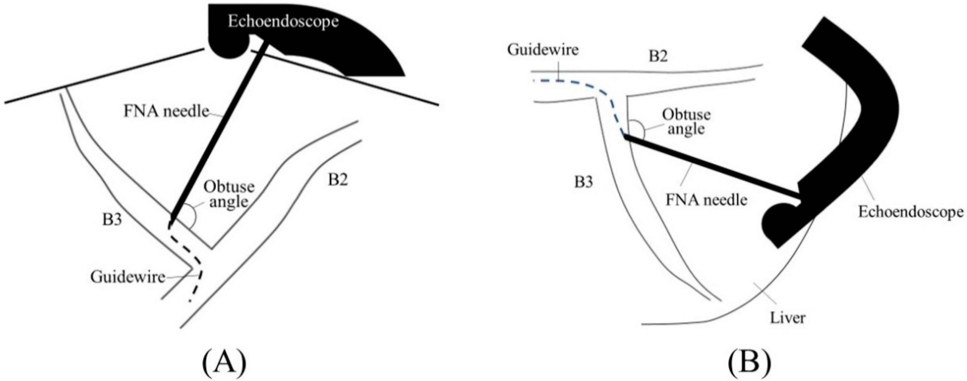
Figure 3. Optimal echoendoscope position in B3 puncture. Pushing a scope while turning the large wheel upward rotates the EUS image clockwise and makes the angle between a needle and the bile duct on the hilar side obtuse, making a guidewire manipulation toward the hilar region easy (A). Fluoroscopic image (B).
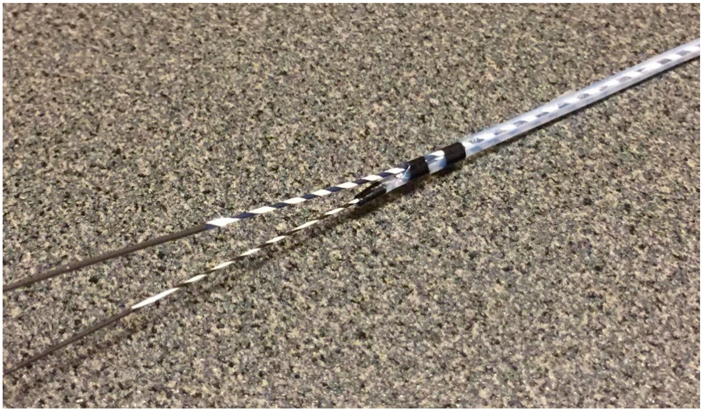
Figure 4. Uneven Double Lumen Cannula (Piolax Medical Device). The double lumen catheter allows a second 0.035 inch guidewire to be inserted adjacent to the first 0.025 inch guidewire. (Courtesy of Piolax Medical Device).
2.2. Biliary Puncture
There are various types of FNA needles, each with a different tip shape and different materials for the needle and sheath. Nitinol needles are more flexible and less prone to bending than steel needles. Additionally, the coil sheath has a higher lumen retention when bent than the plastic sheath. These properties are useful for performing EUS-HGS. The EZ-shot 3 plus (Olympus Medical Systems) (Figure 75A) is the only commercially available nitinol needle with a coil sheath. In EUS-HGS, one of the most difficult steps is the manipulation of the guidewire through the needle [31][22]. The main issue is guidewire shearing, which in turn created a risk of leaving a tip of the guidewire in the patient. The EchoTip Access Needle (Cook Medical, Winston Salem, NC, USA) is a dedicated needle for interventional EUS, which has a sharp stylet for puncture, and the needle tip becomes blunt when the stylet is removed, thus avoiding guidewire shearing [17,32][23][24] (Figure 75B).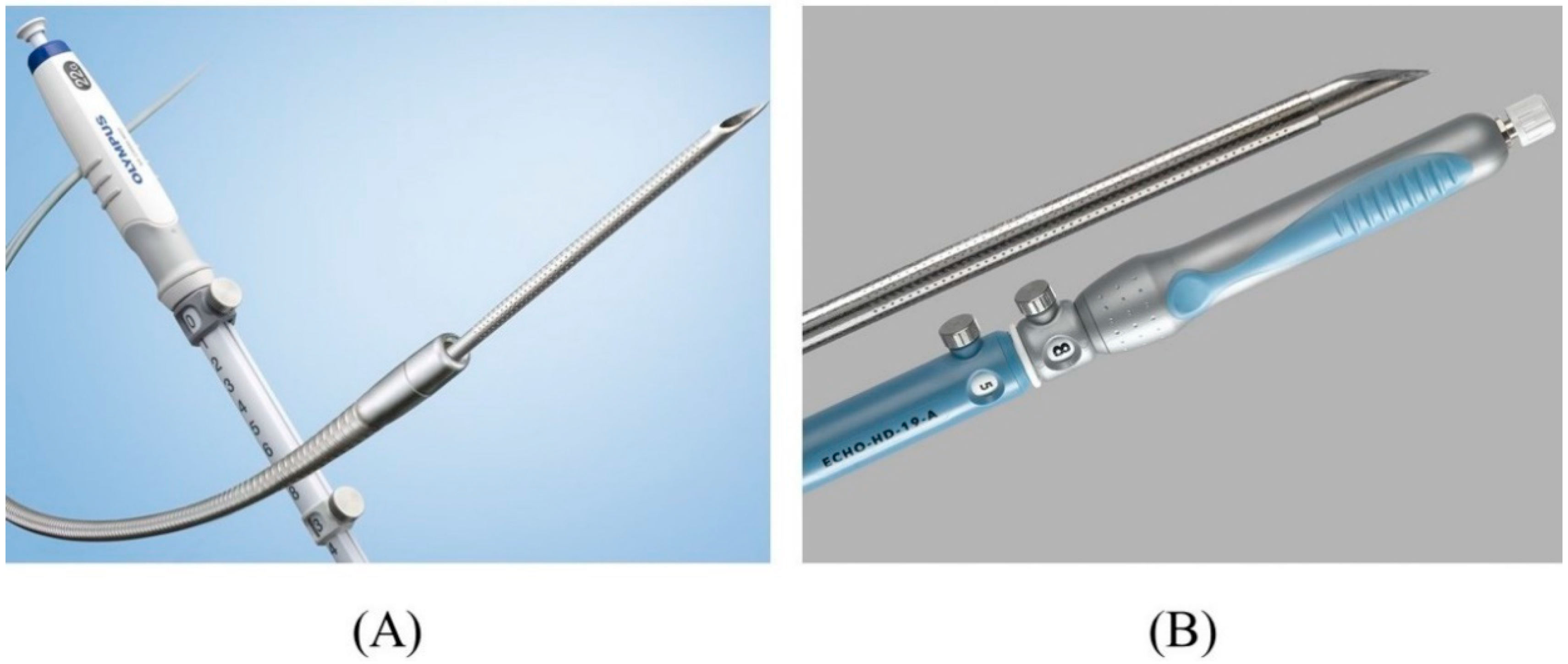
Figure 75. Needles suitable for EUS-HGS. EZ shot 3 plus (Olympus Medical Systems) has a nitinol needle with a coil sheath (Courtesy of Olympus Medical Systems) (A). EchoTip Access Needle (Cook Medical) has a sharp stylet and blunt-tipped needle (Courtesy of Cook Medical) (B).
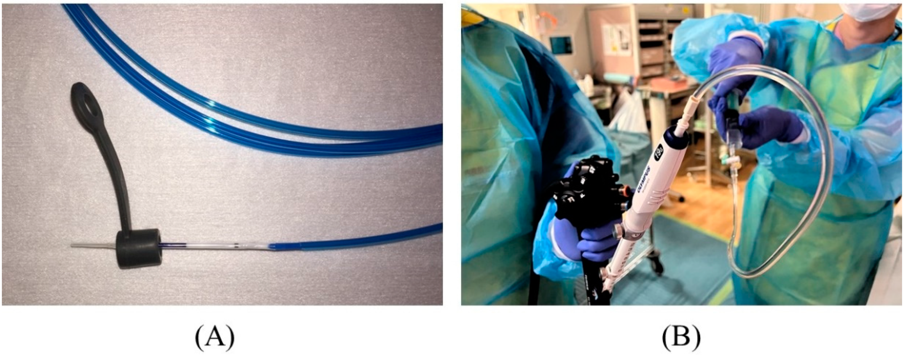 Figure 86. Preparation for puncture. The biopsy valve is attached to a dilation device (A). The needle stylet is removed, and a syringe filled with contrast medium is attached to the needle to pre-fill the lumen with contrast medium (B).
2.3. Contrast Injection
If contrast medium is injected directly after bile duct access, the intraductal pressure will increase. The increased intraductal pressure may not only cause bile leak but also cause cholangio-venous reflux, which may lead to bacteremia in case of cholangitis. Therefore, it is necessary to aspirate as much bile as possible before injecting the contrast medium. Ishiwatari et al. reported in a retrospective study that bile aspiration of 10 mL or more was a significant factor in reducing the occurrence of adverse events associated with bile leak [36][25]. In this study,A a catheter was inserted into the bile duct to aspirate bile prior to tract dilation, which requires more steps in the procedure; therefore, bile aspiration with an FNA needle seems preferable. Following bile aspiration, contrast medium is injected to depict the biliary tract. In order to improve the handling of the guidewire through the needle and the visibility of the guidewire under fluoroscopy, it is recommended to use a contrast medium diluted to half its concentration in saline. The amount of contrast medium injected should be limited to the minimum amount that will allow the hilar region to be visualized to avoid increased intraductal pressure.
2.4. Guidewire Manipulation
When using a 19-gauge needle, a 0.035 inch or 0.025 inch guidewire can be used. However, the 0.025 inch guidewire is preferable because there is less risk of the guidewire being sheared by the needle tip and it is easier to manipulate. In recent years, a number of 0.025 inch guidewires have been released, such as VisiGlide2 (Olympus Medical Systems), EndoSelector (Boston Scientific Corp, Natick, MA, USA), M-Through (Medicos Hirata, Osaka, Japan), and INAZUMA (Kaneka Medix, Osaka, Japan), which have a hydrophilic coating on the tip, a stiff shaft, and excellent torque and supportability. When using a 22-gauge needle, a 0.021 inch or 0.018 inch guidewire can be used, but the performance of these conventional guidewires has not been sufficient. Most recently, a new 0.018 inch guidewire (Fielder 18; Olympus Medical Systems) has been released, which has a high performance similar to that of the 0.025 inch guidewire [22,37,38][26][27][28].
The guidewire is advanced through the needle, and once it enters the bile duct, it is slowly and carefully advanced with gentle rotation to guide it toward the hilar region. If the guidewire is unintentionally advanced to the peripheral side, the “Loop technique” should be attempted first. Push the guidewire with rotation, and when the tip of the guidewire is caught on a lateral branch (Figure 107A), push the guidewire further. Since the tip of the guidewire is fixed, the body of the guidewire will bend with the pushing force and form a loop (Figure 107B). If the loop is facing the hilar region, the guidewire can be advanced to the hilum by pushing further (Figure 107C,D). If the “Loop technique” fails, the “Moving scope technique” is an alternative to change the direction of the guidewire, where pushing the scope while turning the large wheel upward may change the direction of the needle to the cranial side, allowing the guidewire to proceed toward the hilum [39][29] (Figure 118A–C).
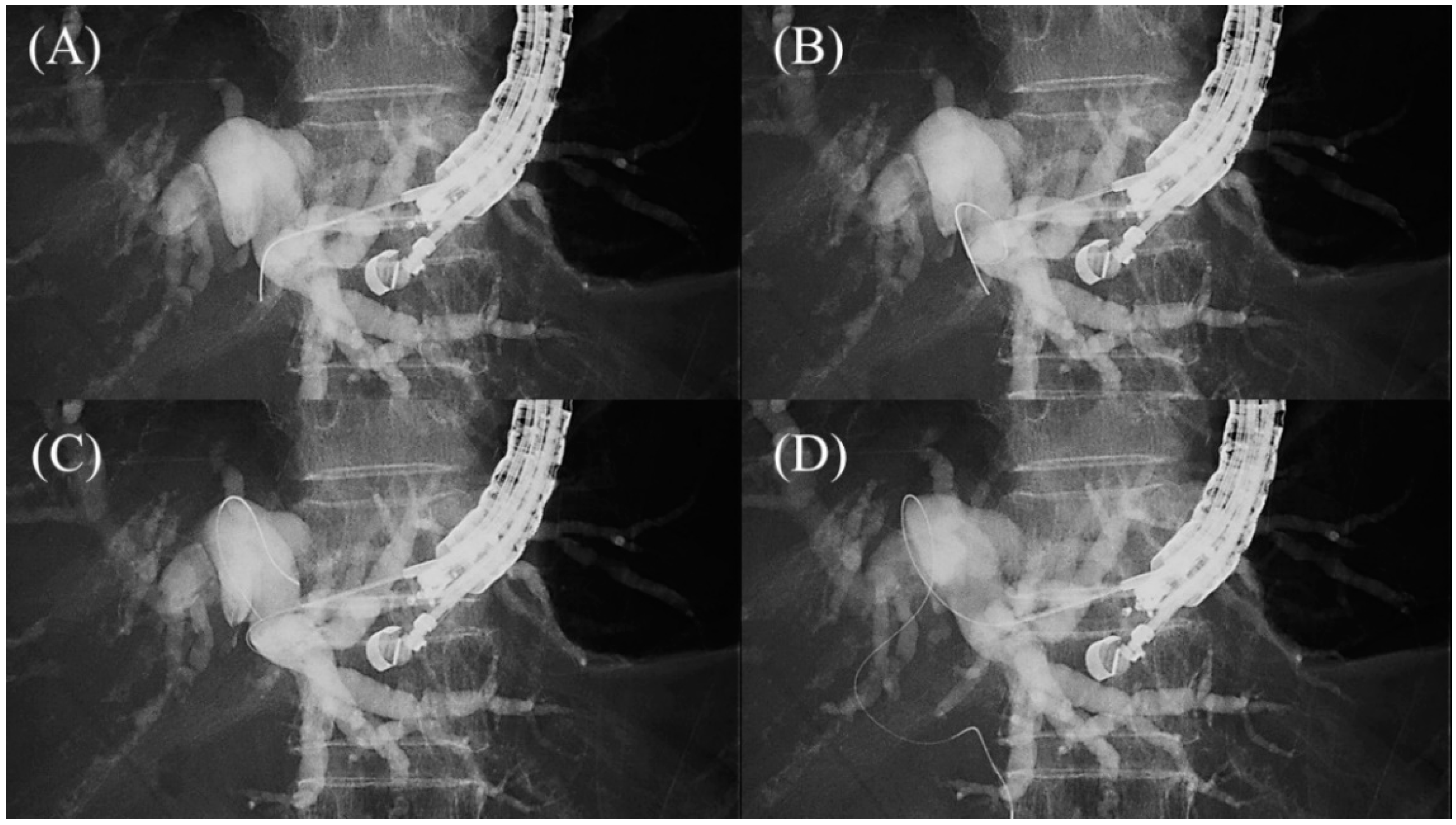 Figure 107. Loop technique for redirection of a guidewire. If a guidewire is unintentionally advanced to the peripheral side, push the guidewire with rotation. When the tip of the guidewire is caught on a lateral branch (A), the guidewire will bend and form a loop by pushing force (B). If the loop is facing the hilar region, the guidewire can be advanced to the hilum by pushing further (C,D).
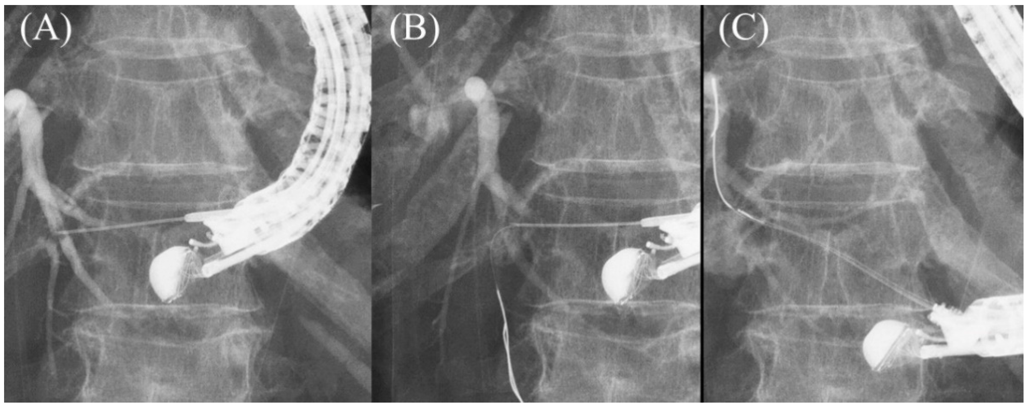 Figure 118. Moving scope technique for redirection of a guidewire. If a guidewire is unintentionally advanced to the peripheral side (A,B), push the scope while turning the large wheel upward to change the needle direction to the cranial side, allowing the guidewire to proceed toward the hilum (C).
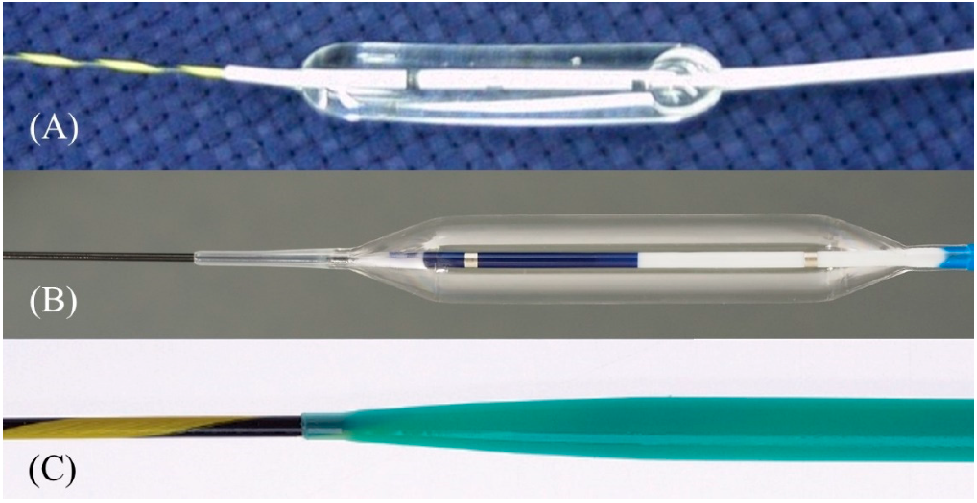 Figure 149. One-step mechanical dilation devices. Hurricane (Boston Scientific) is a balloon dilator with a rigid shaft and stylet (Courtesy of Boston Scientific) (A). REN (Kaneka Medics) is a balloon dilator with an ultra-tapered tip adapted to a 0.025 inch guidewire (Courtesy of Kaneka Medics) (B). ES dilator (Zeon Medical) is a bougie dilator with an ultra-tapered tip adapted to a 0.025 inch guidewire. (Courtesy of Zeon Medical) (C).
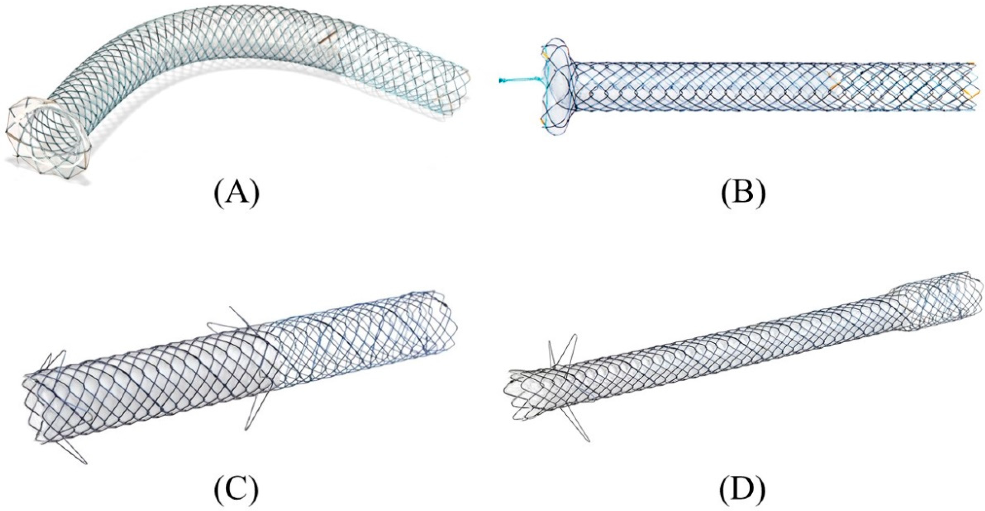 Figure 160. Partially covered SEMSs with anti-migration properties dedicated for EUS-HGS developed by Korean companies. GIOBOR stent (Taewoong medical) (A). HANARO stent BPD (M.I.Tech, Seoul, Korea) (B). Hybrid BONA stent (Standard Sci. Tech, Seoul, Korea) (C). DEUS (Standard Sci. Tech) (D). Courtesy of each company.
Figure 107. Loop technique for redirection of a guidewire. If a guidewire is unintentionally advanced to the peripheral side, push the guidewire with rotation. When the tip of the guidewire is caught on a lateral branch (A), the guidewire will bend and form a loop by pushing force (B). If the loop is facing the hilar region, the guidewire can be advanced to the hilum by pushing further (C,D).
Figure 118. Moving scope technique for redirection of a guidewire. If a guidewire is unintentionally advanced to the peripheral side (A,B), push the scope while turning the large wheel upward to change the needle direction to the cranial side, allowing the guidewire to proceed toward the hilum (C).
2.5. Tract Dilation
After a sufficient length of guidewire is placed, the needle is replaced with a dilatation device. In ERCP, the elevator is usually raised completely after device removal to prevent guidewire dislodgement. However, in EUS-HGS, the elevator should not be raised further after the needle is removed, because it is most critical to maintain ultrasound visualization of the puncture line to ensure subsequent device insertion. The more skilled the physician is in ERCP, the more likely it is that he or she will do this unconsciously, so care must be taken. The dilatation of the tract is carried out using a mechanical dilator such as a bougie dilator or balloon dilator, or a diathermic dilator. The bougie dilator is the safest, but insertion of an introducer of covered SEMS is often difficult because the size of the hole opened on the bile duct is the smallest, usually only 7 Fr. The balloon dilator can make the largest hole, but it is associated with the risk of bile leak. The diathermic dilator is the most reliable in penetrating the bile duct wall, but the burning effect can cause bleeding from the surrounding liver parenchyma and hepatic artery. Therefore, the bougie dilator is appropriate for stents with small caliber introducers (7 Fr or less), such as plastic stents and some kinds of covered SEMS, while the balloon dilator is suitable for conventional covered SEMS where the introducer is usually 8 Fr or more. The diathermic dilator had better be used as a rescue when the bile duct wall is too hard to be breached by other dilators [8]. In the initial era of EUS-HGS, mechanical dilation was accomplished gradually: the ERCP catheter was inserted first after the needle removal, followed by sequential dilatation with a bougie dilator or balloon dilator [45,46,47][30][31][32]. Recently, however, the properties of mechanical dilators have been improved so that they can be inserted directly without dilation by the ERCP catheter. Balloon dilators include Hurricane RX (Boston Scientific Corp), which has a rigid shaft with a stylet (Figure 149A) [46][31], and REN (Kaneka Medics), which has an ultra-thin tip of 3 Fr (Figure 149B) [48][33]. ES dilator (Zeon Medical, Tokyo, Japan) is a 7 Fr bougie dilator which has an ultra-thin tip of 2.5 Fr (Figure 149C) [49,50,51][34][35][36]. REN and ES dilator are dedicated dilation devices for EUS-HGS that are adapted to 0.025 inch guidewires, and the gap between the tip of these devices and the 0.025 inch guidewire is extremely small.
Figure 149. One-step mechanical dilation devices. Hurricane (Boston Scientific) is a balloon dilator with a rigid shaft and stylet (Courtesy of Boston Scientific) (A). REN (Kaneka Medics) is a balloon dilator with an ultra-tapered tip adapted to a 0.025 inch guidewire (Courtesy of Kaneka Medics) (B). ES dilator (Zeon Medical) is a bougie dilator with an ultra-tapered tip adapted to a 0.025 inch guidewire. (Courtesy of Zeon Medical) (C).
2.6. Stent Deployment
In the early days of EUS-HGS, plastic stents were predominantly used [55,56,57,58][37][38][39][40]. Although plastic stents are inexpensive and easy to place, they are prone to stent clogging due to their small caliber and bile leakage due to their lack of self-expandability. Therefore, conventional biliary-covered SEMS with a length of 6 cm or 8 cm have come into use in the expectation of preventing bile leaks by closing the fistula with self-expandability and prolonging the stent patency period with a large diameter [59,60][41][42]. In fact, the adverse events of EUS-HGS with a covered SEMS have been reported to be lower than with a plastic stent [53][43]. However, the migration of the gastric end of the stent into the abdominal cavity leading to fatal biliary peritonitis has been recognized as a major problem with a covered SEMS. For this reason, some experts initially recommended the use of a plastic stent for EUS-HGS and its replacement with a covered SEMS after fistula maturation [61,62][44][45]. However, recent advances in methodology and instrumentation have made it possible to prevent migration. Currently, various types of SEMS are available for EUS-HGS with respect to stent design (braided or laser-cut type), coverage (partial or full), presence or absence of anti-migration properties at the gastric end, and size of the introducer. As a dedicated device for EUS-HGS, several partially covered braided SEMSs with anti-migration properties have been released by Korean companies (Figure 160A–D) [17,73,74,75,76,77,78,79][23][46][47][48][49][50][51][52]. In Japan, the most common SEMS for EUS-HGS is Niti-S S-type stent (modified Giobor stent; Taewoong Medical, Seoul, Korea), which is a partially covered SEMS with a 1 cm uncovered portion at the hepatic end [71,80][53][54]. Since this stent is a braided SEMS with a cross-wire structure, it gradually expands in the stomach from the non-expanded part in the gastric wall to form a smooth and gently sloping stent surface. Therefore, the effect of holding down the gastric wall is weak. Furthermore, the shortening rate of the stent is large, which tends to cause delayed migration of the gastric end into the peritoneal cavity (Figure 17A–C). In order to prevent this, the stent length should be longer than 10 cm, but even a long stent cannot prevent it completely as mentioned above. For this reason, Niti-S Spring Stopper Stent (Taewoong Medical) was developed with a spring-type stopper at the gastric end to prevent migration (Figure 18). This stent can reliably prevent delayed migration of the gastric end. Meanwhile, pre-dilation of the tract is usually required for these SEMSs insertion because the diameter of the introducer is 8.5 Fr.
Figure 160. Partially covered SEMSs with anti-migration properties dedicated for EUS-HGS developed by Korean companies. GIOBOR stent (Taewoong medical) (A). HANARO stent BPD (M.I.Tech, Seoul, Korea) (B). Hybrid BONA stent (Standard Sci. Tech, Seoul, Korea) (C). DEUS (Standard Sci. Tech) (D). Courtesy of each company.
3. Conclusions
Herein describes the technical tips for safe and successful EUS-HGS, in particular the method using a covered SEMS for palliative drainage purposes. Recent advances and innovation in EUS systems, equipment, and methods have made EUS-HGS an easier and safer procedure, but the risk of serious adverse events such as stent migration and bile leak still remains. The techniques described here are all practical and should be readily available, especially for physicians who are just starting EUS-HGS. It is hoped that further advances in instrumentation will make EUS-HGS safer and more reliable.