Your browser does not fully support modern features. Please upgrade for a smoother experience.
Please note this is a comparison between Version 3 by Camila Xu and Version 2 by Camila Xu.
The nitrogen bond in chemical systems occurs when there is evidence of a net attractive interaction between the electrophilic region associated with a covalently or coordinately bound nitrogen atom in a molecular entity and a nucleophile in another, or the same molecular entity. It is the first member of the family of pnictogen bonds formed by the first atom of the pnictogen family, Group 15, of the periodic table, and is an inter- or intra-molecular non-covalent interaction.
- pnictogen bonding
- nitrogen as pnictogen bond donor
- geometries
- intermolecular distance
- directionality
- molecular electrostatic potential
- charge density isosurfaces
- Crystal structure analysis
- π-hole interactions
- σ-hole interactions
- CSD and ICSD database
1. Introduction
IUPAC definitions, features and characteristic properties that can be used to identify non-covalent interactions, such as hydrogen bonding, chalcogen bonding and halogen bonding in chemical systems have been promulgated in 2011 [1], 2013 [2] and 2019 [3], respectively. A task group has been charged with categorizing tetrel bonding, pnictogen bonding, and other non-covalent interactions, involving the elements of Groups 14–16 of the periodic table [4]. The proposed characteristics of these bonding interactions have emerged from observations of a variety of engineered chemical systems in the crystalline, liquid and gas phases, and examining signatures arising from IR [5][6], Raman [7][8], UV/vis [9][10], and NMR [10][11] methods, and from ab initio and density functional theory calculations [12][13][14]. The characteristic features vary from system to system because they are dependent on the nature of the electron density distribution associated with the electron donor and electron acceptor fragments driving the non-covalent interactions.
In this featured research, researchers show that nitrogen in molecular entities can act as an electrophile when covalently bonded with appropriate electron-withdrawing atomic domain(s). This electrophilic feature of N can form nitrogen-centered pnictogen bonding interactions (or simply nitrogen bonding interactions) when in close proximity with a negative site on the same or a neighboring molecule, and hence is responsible in part for the stability of the resulting supermolecular or intramolecular entity.
The nitrogen bond in chemical systems occurs when there is evidence of a net attractive interaction between the electrophilic region associated with a covalently or coordinately bound nitrogen atom in a molecular entity and a nucleophile in another, or the same molecular entity. It is the first member of the family of pnictogen bonds formed by the first atom of the pnictogen family, Group 15, of the periodic table, and is an inter- or intra-molecular non-covalent interaction.
A nitrogen bond in a molecular entity may be regarded as a σ-hole centered pnictogen bond, especially when the covalently bound nitrogen features a positive σ-hole along the R–N bond extension, where R is the remainder of the molecular entity and is in attractive engagement with a negative site in the same or a neighboring molecule. A σ-hole is defined as a charge density deficient region on an atom A that appears along the outer extension of the R–A covalent bond [15][16]. By contrast, a nitrogen bond may be regarded as a π-hole centered pnictogen bond when the nitrogen in molecular entities features a π-hole [17] on its electrostatic surface and has the ability to engage attractively with a negative site in a neighboring molecule, or a site that has an electron density different to that of the π-hole, thus providing stability to the geometry of the resulting structure. A σ-hole interaction in a chemical system is generally observed to be directional, whereas a π-hole is non-directional. There are many studies on σ-hole and π-hole [17] interactions in chemical systems, including similarities, differences, controversies and misconceptions [18][19][20][21][22][23][24][25].
Nevertheless, nitrogen is a crucial constituent in the development of high-density materials, and, of course, is crucial for ammonia synthesis [26][27][28][29]. Apart from its well-known use as a feedstock for the production of fertilizers [30], researcher may be on the brink of a viable ammonia economy [31]. “Green ammonia” is a carbon-free hydrogen-containing compound with immense interest due to its high density and high hydrogen storage capability [29][32][33][34].
WResearchers considered nitrogen because a fundamental understanding of its modes of interaction in forming complex chemical systems would surely elevate the current knowledge of nitrogen-centered pnictogen bonding (i.e., nitrogen as a pnictogen bond donor). The role of pnictogen bonding containing heavier members of the pnictogen family (viz. P, As, Sb and Bi) in catalysis has also been demonstrated on several occasions [35][36][37][38], and in other areas, such as anion transport and recognition chemistry [39], solution and gas-phase chemistry [40][41][42], computational chemistry [13], supramolecular chemistry [43], coordination chemistry [44][45], medicinal chemistry [46], crystallography [47][48] and crystal engineering [49][50], among other research fields.
Nitrogen is the lightest member of the pnictogen family (Group 15), and the third most electronegative element after fluorine and oxygen. When it is present in a molecular entity, it is well known to be a site for interaction with electrophiles [51]. HCN, N2, NO, HCCCN, CH3CN, and NO−3 are a few examples where nitrogen is entirely negative, and hence, serves as a site to interact with electrophiles to form molecular complexes in the gas phase or adducts in the solid state. Nitrogen in molecules, such as NH3 and in amines, is often found, both experimentally and theoretically [52][53], to be negative. This is a consequence of its strong electronegative character. It is also less polarizable than the other members of the pnictogen family. Its lone-pair electrons, if visualized from a Lewis structure viewpoint, dominate along the extension of the R–N covalent bonds in compounds in which it is covalently bonded and is an electron density donor towards electrophiles, forming hydrogen bonds, halogen bonds or chalcogen bonds, and acts as a Lewis base to metal ions [54]. This is the probable reason why fluorine, oxygen and nitrogen—being highly electronegative but with low polarizability—often have a negative σ-hole [21]. However, under certain circumstances, nitrogen can act as an acceptor of electron density, for example, in hypervalent non-covalent interactions, as demonstrated by Chandra and coworkers [55]. They observed an intermolecular interaction between nitromethane, CH3NO2 and NH3 at low temperature within an inert gas matrix, which was characterized by IR spectroscopy and supported by first-principles calculations. The nitrogen in CH3NO2 acts as an electron density acceptor from the nitrogen in NH3, forming a CH3O2N···NH3 dimer and is stabilized by an N···N pnictogen bond. The directional prevalence of this interaction over the C–H···N and N–H···O hydrogen bonding interactions was shown by ab initio calculations, demonstrating that σ-hole/π-hole driven interactions lead to the formation of the dimer, despite nitrogen’s low polarizability.
2. The Solid-State Structure of Dinitrogen, N2
WResearchers begin by looking at dinitrogen itself. Solid N2 displays exceptional polymorphism under extreme conditions. Some of its known phases include α, β, γ, δ, ε, ι and θ [56][57][58]. Because the phases of the crystal depend on an external agency (temperature and pressure), the packing is different in each phase. Consequently, the intermolecular interactions between the N2 molecules in these crystals are different.
The α-phase (third allotrope) of solid N2, with Z = 4, space group Pa-3, Figure 1a, determined using electron diffraction measurements [59], is mainly stabilized by π···N (lone-pair) interactions between the N2 molecules. The centers of the N2 molecules are on an f.c.c. lattice with each molecule pointing in a different direction. The intermolecular distance between N in one molecule and the midpoint of the π bond in a neighboring molecule is 3.565 Å. Researcher attribute this interaction to π-centered pnictogen/nitrogen bonding.
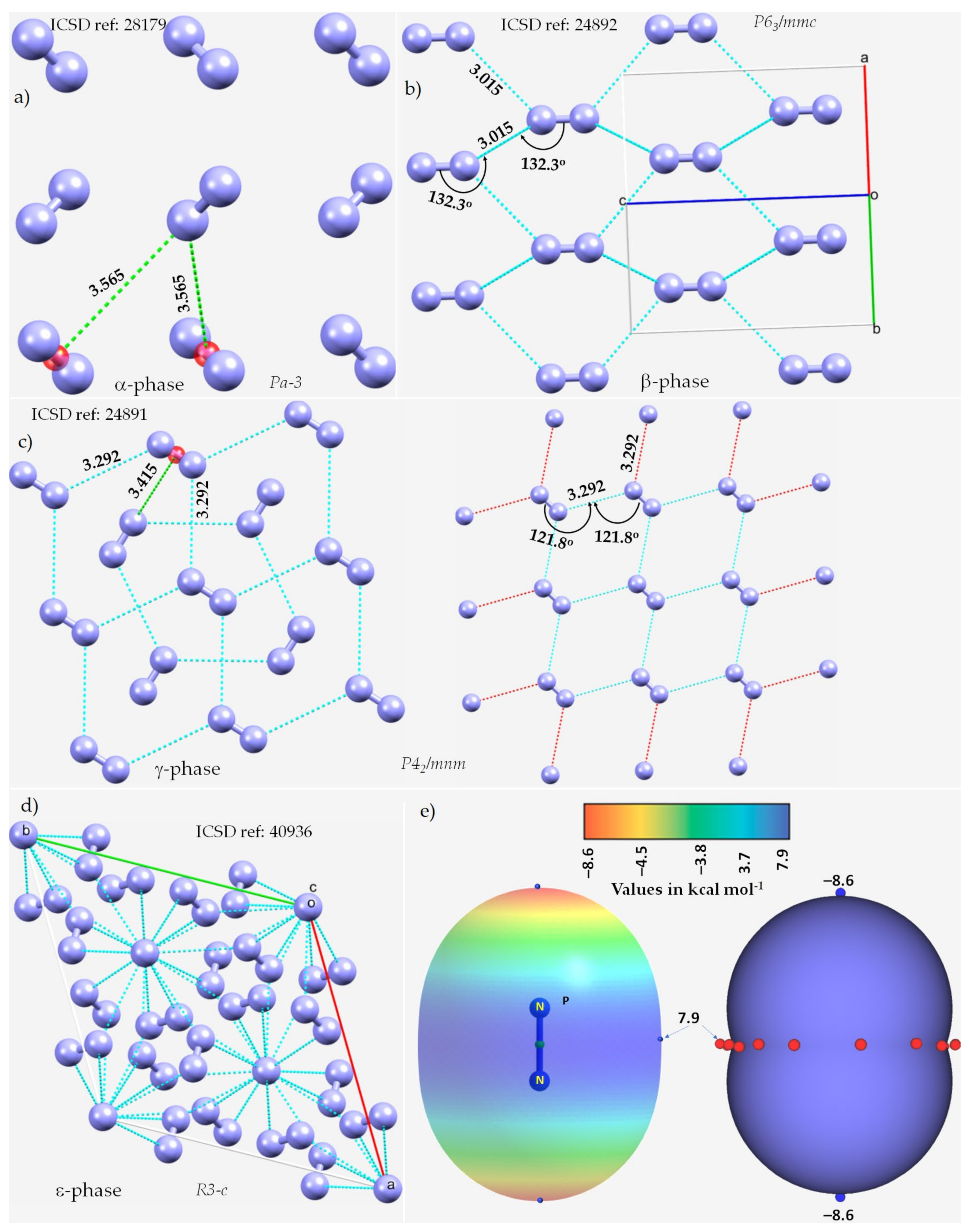
Figure 1. The nature of bonding interactions between the N2 molecules in the crystals of (a) α-N2, (b) β-N2, (c) γ-N2, and (d) ε-N2. (e) The 0.001 a.u. isodensity mapped MESP plot of an isolated N2 molecule, obtained at the MP2(full)/aug-cc-pVTZ level of theory. The local most minima and maxima of potential are marked by tiny circles in blue and red, respectively. Selected bond lengths and bond angles are in Å and degree, respectively. Crystallographic axes are not shown in (a,c) for clarity. The crystal symmetry is shown for each case, together with ICSD references.
The β-phase of hexagonal N2 (Z = 2), Figure 1b [60], comprises two types of intermolecular bonding modes, including N···N and π···π. The first of these contacts occur between the N2 molecules along the crystallographic c-axis, as shown in Figure 1b, with r(N···N) = 3.015 Å and ∠N≡N···N = 132.3°. It is perhaps a Type-Ib topology of pnictogen bonding. The second type of contact is the result of a slip parallel arrangement between the N2 molecules in the crystal along the crystallographic a and b axes, with an intermolecular distance of 3.861 Å between the centroids of a pair of triple bonds on two neighboring N2 molecules (r(π···π) = 3.861 Å).
The γ-phase of tetragonal N2 (Z = 2), Figure 1c [60], consists of N···N and π···N(lone-pair) interactions. The former ones are longer than the latter. Similar to the β-phase, the N···N contacts follow a Type-Ia topology of bonding, with r(N···N) = 3.292 Å and ∠N≡N···N = 121.8°, but are weaker. The π···N (lone-pair) pnictogen bonded interactions have r(N···π) = 3.415 Å and are stronger than the π···π interactions in β-N2. Regardless of the nature of the intermolecular interactions, they are all marginally shorter or somewhat longer than twice the vdW radius of N, 3.32 Å (rvdW(N) = 1.66 Å [61]).
The ε-phase of rhombohedral N2 (Z = 24), Figure 1d [62], has two types of N≡N···N bond distances, r(N···N) = 2.727 Å and 2.801 Å, corresponding to ∠N≡N···N of 133.1° and 120.9°, respectively, and are less than twice the vdW radius of N, 3.32 Å. Additionally, N(lone-pair)···π interactions may be present between the N2 molecules in the crystal, with r(N···π) = 2.958 Å.
The crystal structures of the high-pressure δ and δ* phases of nitrogen were also investigated using single-crystal X-ray diffraction (not shown) [63]. The structure of the δ phase is isostructurally similar to that of γ-O2. Thus, it comprises spherically disordered molecules, with a preference for avoiding pointing along the cubic ⟨100⟩ directions, and disk-like molecules with a uniform distribution of orientations. The structure of the δ* phase is tetragonal, and the space group was identified unambiguously as P42/ncm at 14.5 GPa.
WResearchers did not observe any potentially directional interactions in either of the pressure-induced phases of N2. In all cases, the N···N interactions follow a Type-Ia/Type-Ib topology of bonding and occur between interacting sites of dissimilar electron density. The possibility of the N···N and π···N (lone-pair) interaction can be inferred from the MESP model of an isolated molecule, Figure 1e. The delocalized bonding region in N≡N is equipped with a belt of positive potential characterized by near equivalent local most maxima (tiny red spheres). In contrast to what might be expected on the surface of a covalent bound halogen in a molecular entity, such as, for example, in HBr and HCl, researcher observed that each N along the N≡N bond extension is accompanied by a local most minima of potential (tiny blue spheres in Figure 1e) and is very negative. This signifies that there is a buildup on charge density on the surface of N along the outer N≡N and the buildup is significant compared to the lateral sites on the same atoms.
3. The Nitrogen Trihalides, NX3 and Their Crystal Structures
WResearchers now discuss a set of other examples in which covalently bound nitrogen acts as an electrophile, as observed in crystalline systems reported over many years. In these systems, covalently bound nitrogen, as in NX3 (X = F, Cl, Br, I), has a positive region on the R–N bond extension that is capable of attracting a negative site on an identical, or in a different molecule. This can be appreciated by looking at the MESPs shown in Figure 2, obtained using ωB97XD/Jorge-ATZP. The top view of Figure 2 shows nitrogen having a positive electrostatic potential along the X–N bond extensions, regardless of the nature of the halogen derivative attached to it. It is largest (16.6 kcal·mol−1) along the F–N bond extensions in NF3. As one passes from NF3 through NCl3 to NBr3, there is a decrease in VS,max from 16.6 kcal·mol−1 to 5.4 kcal·mol−1 to 2.7 kcal·mol−1, and the stability of the σ-hole on N in NX3 occurs in the order X = F > Cl > Br. By contrast, the lone-pair dominated region on N is negative, and the negativity increases in the order NF3 (−4.1 kcal·mol−1) > NCl3 (−11.8 kcal·mol−1) > NBr3 (−14.2 kcal·mol−1). These results demonstrate the amphoteric character of N in NX3.
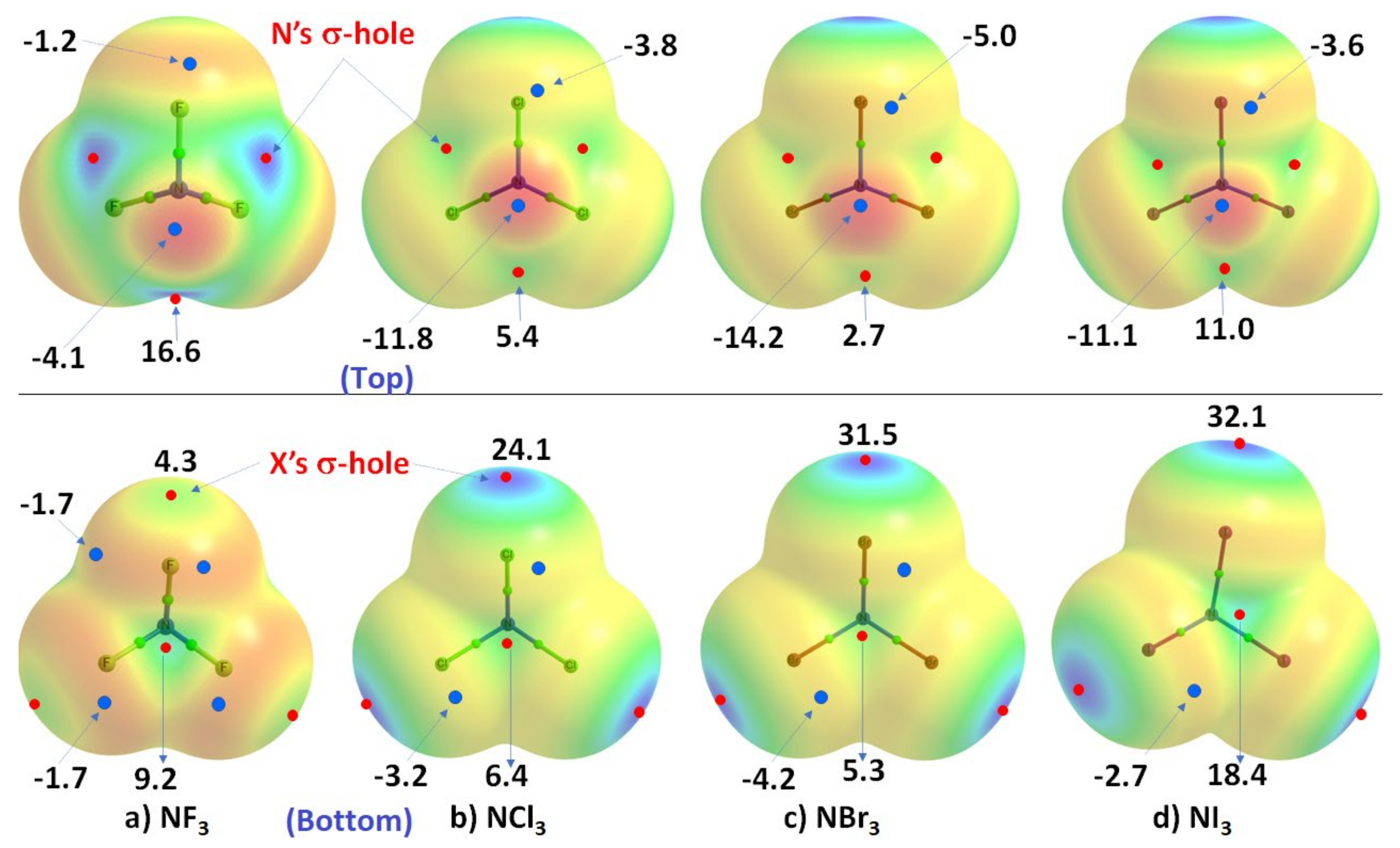
Figure 2. Comparison of the ωB97XD/Jorge-ATZP calculated 0.001 a.u. isodensity envelope mapped potential on the electrostatic surfaces of NX3 (X = F, Cl, Br, I) molecules. Selected VS,max and VS,min values in kcal·mol−1 are shown, which are the local most maximum and minimum of potential (red and blue circles), respectively. Two views of each MESP graph are shown. In the top view, bonded N faces the reader, whereas, in the bottom view, it is the three halogens that face the reader. The Quantum Theory of Atoms in Molecules (QTAIM [64])-based molecular graph is shown for each entity, with the circles in green representing bond critical points and bonds in atom color.
The MESP results for NI3 are also included in Figure 2, but clearly do not follow the same trend noted above. This may be an artifact of the basis set researcher used for these calculations, and clarify this further below. Whilst the numerical values of potential may be out of line, the reactive nature of the N site along and around the I–N bond extensions in NI3 behaves qualitatively similar to that found for the other three NX3 entities.
As shown in the bottom view of Figure 2, VS,max in NX3 increases monotonically from X = F through I along the N–X bond extension, indicating that the magnitude of the σ-holes associated with these potentials increases in the same order and the σ-holes are surrounded by belt-like negative potentials. In other words, the least polarizable F has the smallest σ-hole on N–F bond extensions and the most polarizable I has the largest σ-hole on the N–I bond extensions. The difference in VS,max between NBr3 and NI3 is not large and, as commented above, the MESP values for NI3 with the chosen basis set used may not be very reliable.
In all cases, the central region of the triangular face formed by the three X atoms in each NX3 is found to be positive. The positive and negative nature of VS,max and VS,min on the surface of each constituent atomic domain in NX3 suggest that each of them not only has the ability to form complexes with another identical (or different) molecule but also has the ability to act both as an acid and a base.
In order to determine whether or not the inconsistency in the nature of the negative and positive regions on the surface of specific atoms in the series of four molecules NX3 is a basis set artifact, researcher examined the same properties using another basis set, def2-TZVPD, available in the basis set exchange library [65]. Researcher have also adopted a higher level of theory, MP2, for the same calculation as it is one of the simplest and most useful levels of theory beyond Hartree–Fock that accounts for effects arising from electron–electron correlation. The results are summarized in Table 1.
Table 1. ωB97XD/def2-TZVPD and MP2(full)/def2-TZVPD computed 0.001 a.u. isodensity envelope mapped the local most minima and maxima of potential on the electrostatic surfaces of NX3 (X = F, Cl, Br, I) molecules. VS,max and VS,min values in kcal·mol−1.
| Species | NF3 | NCl3 | NBr3 | NI3 | ||||
|---|---|---|---|---|---|---|---|---|
| Method | ωB97XD | MP2 (Full) | ωB97XD | MP2 (Full) | ωB97XD | MP2 (Full) | ωB97XD | MP2 (Full) |
| Extrema of potential | Vs,max | |||||||
| N–X (one on each X) | 4.7 | 5.2 | 25.0 | 24.5 | 29.7 | 28.2 | 36.3 | 32.1 |
| X–N (one on each extension) | 16.5 | 16.5 | 5.2 | 4.6 | 3.5 | 3.5 | 2.1 | 2.3 |
| Center of the triangular X3 face | 8.8 | 7.5 | 5.6 | 4.9 | 5.4 | 4.3 | 6.4 | 4.9 |
| VS,min | ||||||||
| On lone-pair region on N | −4.1 | −3.7 | −11.9 | −12.6 | −14.1 | −13.8 | −17.2 | −15.2 |
| On F (within the X3 face) | −1.8 | −1.9 | −3.7 | −3.4 | −4.3 | −3.9 | −4.9 | −4.0 |
| On X (opposite of the X3 face) | −1.3 | −1.3 | −4.0 | −4.1 | −4.8 | −4.6 | −5.3 | −4.8 |
As can be seen from the data in Table 1, and regardless of the correlated method used in conjunction with the def2-TZVPD basis set, the N has a positive σ-hole along the X–N bond extensions. These σ-holes become less positive as the size of the halogen in NX3 increases from F down to I, and there are three equivalent holes on N in each NX3. By contrast, the halogen derivative has a single σ-hole on its surface along the N–X bond extension, so there are also three positive σ-holes on the surfaces of the three X atoms that are also equivalent (only one is listed in Table 1). They systematically increase with the increasing size of the halogen in NX3, in agreement with what might be expected from their polarizabilities.
3.1. Nitrogen Trifluoride, NF3
The crystal structure of NF3 was reported only recently, and corresponds to the low-temperature α-phase [66]. Since powder neutron diffraction measurements were performed, it is expected that the intermolecular geometry is more accurate than might have been obtained from X-ray diffraction measurements.
The α-phase of NF3 crystallizes in the orthorhombic space group Pnma, with lattice parameters a = 6.71457(13) Å, b = 7.30913(14) Å, c = 4.55189(8) Å, cell volume (V) = 223.396(7) Å3, and Z = 4 at T = 6 K. The β-phase of NF3 corresponds to a high-temperature phase and was observed to be a plastic crystal (space group P4/mnm) with lattice parameters a = 15.334(6) Å, c = 7.820(3) Å, V = 1838.6(12) Å3, and Z = 30 at T = 60 K. It was suggested that the crystal structure of this latter phase is closely related to that of the Frank–Kasper sigma phase, but the one deposited in the ICSD (ref. code 1891641) does not contain the geometry of β-NF3 (the fluorine atoms are missing).
The unit-cell of the α-phase comprises four units of NF3, as shown in Figure 3a. It shows the intermolecular bonding modes between the building blocks responsible for the unit-cell of the NF3 crystal; these are consistent with the attraction between the positive and negative sites of electrostatic potential localized on different atomic domains (Figure 3b). In particular, Type-IIa N–F···F and F–N···F non-covalent interactions are observed and are inferred from the intermolecular distances and angles of interaction. The former is less directional but shorter than the latter (Figure 3a).
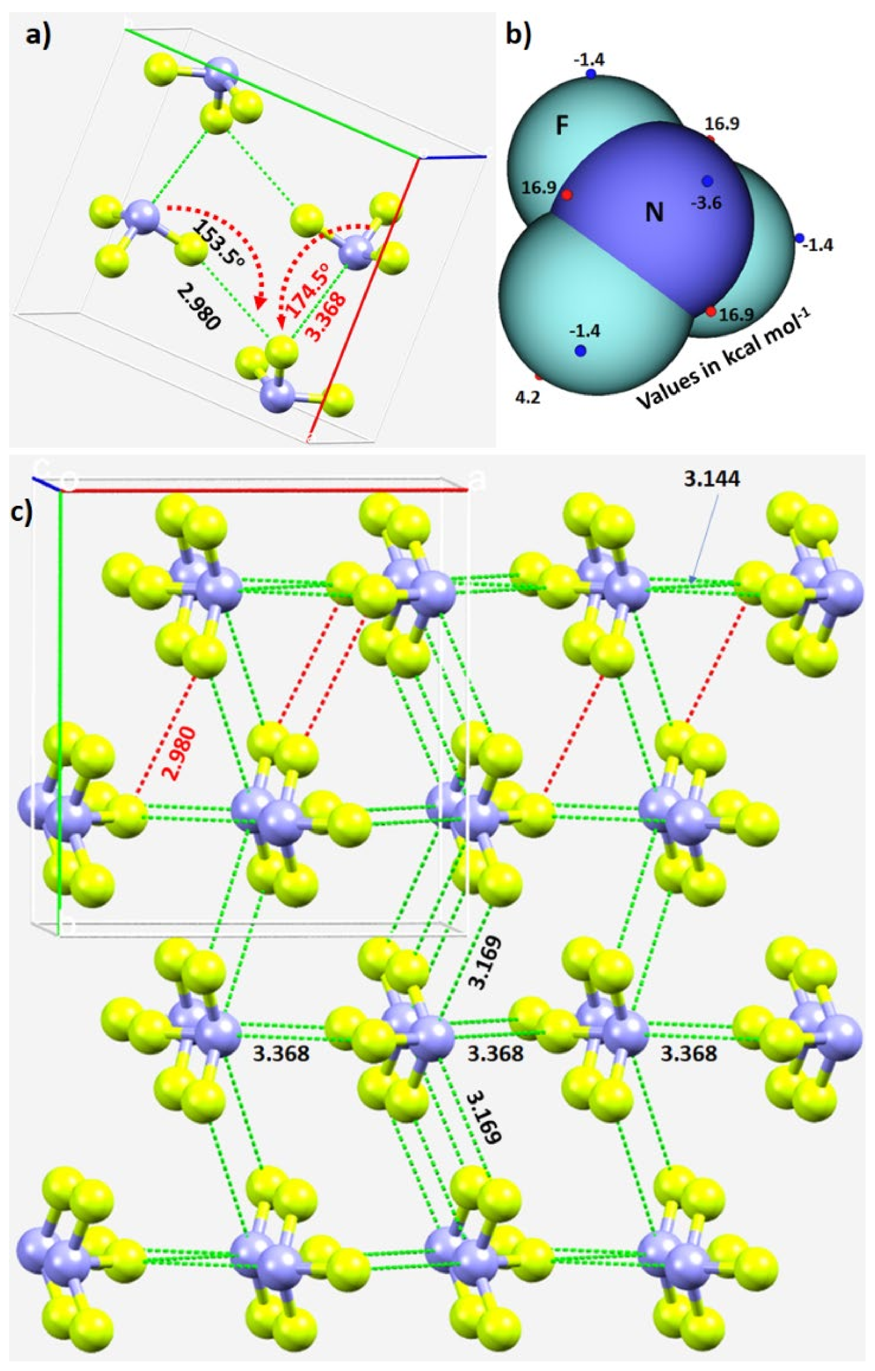
Figure 3. (a) The unit-cell of α-NF3 (CSD ref. code 1891640), showing selected N···F and F···F σ-hole-centered intermolecular interactions and the intermolecular angles for the approach of the electrophile. (b) Illustration of selected local maximum and minimum of electrostatic potential (red and blue spheres, respectively) mapped on the 0.001 a.u. isoelectron density surface of NF3 obtained at the ωB97XD/aug-cc-pVTZ level of theory. (c) The network of N···F and F···F σ-hole centered pnictogen and halogen bonding interactions in 2 × 2 supercell geometry of α-NF3. Bond lengths and bond angles in Å and degrees, respectively. Dotted lines represent intermolecular interactions.
The real nature of the intermolecular interactions between the molecular units in the crystal may not be apparent in inspecting the unit-cell alone; a periodic extension of the unit-cell is necessary. The 2 × 2 supercell structure of α-NF3 is shown in Figure 3c. Although there are many more interactions between the molecules of NF3 in the crystal, researcher have highlighted in Figure 3c only the prominent bonding modes formed by the N site. As revealed by the MESP model (Figure 2a), the three positive sites along the F–N bond extensions do indeed donate pnictogen-centered σ-hole bonds to the lateral portions of the F sites in the nearest NF3 units (Figure 3a). Of the three, two are equivalent and the other is longer (3.169 Å vs. 3.368 Å). They are all directional since ∠F–N···F for each of the two equivalent interactions is 172.3° and that for the longer bond is 174.5° (Figure 3a).
In crystalline α-NF3, the nitrogen in the NF3 molecule acts as a hexa-furcated center in donating σ-hole bonds. It donates three highly directional σ-hole bonds (vide supra) and two relatively less directional equivalent σ-hole bonds (r(N···F) = 3.301 Å and ∠F–N···F = 143.4°) that are caused by the attraction between the positive site on the central region of the surface formed by the three fluorine atoms in one molecule and the negative region dominated by the lone-pair of a neighboring molecule, thereby forming five pnictogen bonds (Figure 4a,b). Because nitrogen has a negative site (readily appreciated in its Lewis structure) evidenced by the VS,min = −3.6 kcal·mol−1 shown in Figure 2a, it shows a tendency to accept a σ-hole bond from the covalently bound fluorine of another interacting NF3 molecule, responsible for the formation of an F···N halogen bond (Figure 4b). The back-to-back arrangement between the NF3 molecules, Figure 4a, causing the additional intermolecular interactions noted above, is a result of a π(N)···π(N) interaction. The behavior of N in forming so many non-covalent interactions appears to be unique to this system.
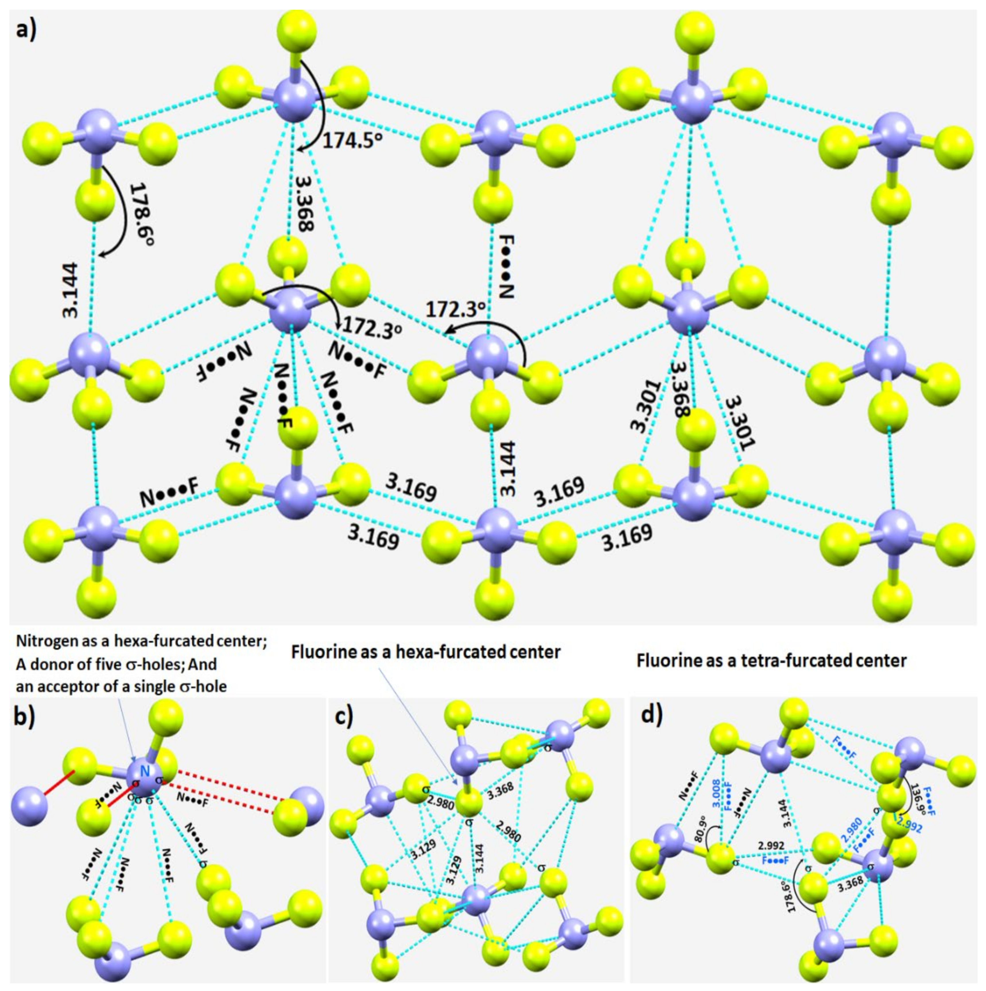
Figure 4. (a) Nature of N···F pnictogen bonds in the α-phase of the NF3 crystal. (b–d) Nature of the local topology of intermolecular bonding interactions around N and F in NF3. Bond lengths and bond angles in Å and degrees, respectively. The symbol “σ” on N/F in (b–d) refers to the covalently bonded atom donating the σ-hole.
Our investigation shows that fluorine has the ability to act both as a hexa- and tetra-furcated center, as shown in Figure 4c,d, respectively. It is evident from Figure 4c that fluorine is an acceptor of three σ-hole bonds, thus forming one F–N···F and two N–F···F halogen bonds; it is a donor of a single σ-hole bond, forming an N–F···N halogen bond; and it shows capacity to form two or more N–F···F–N halogen-bonded Type-Ia and/or Type-Ib interactions—all within a distance of 2.90–3.20 Å. The Type-Ia N–F···F–N halogen-bonded contacts, such as those marked in Figure 4d, are commonly observed in fully fluorinated compounds, for example, the crystal of C6F6 [67], and in similar compounds [68][69][70]. Clearly, the complex topology of bonding between the NF3 molecules in the crystal structure requires a variety of theoretical studies to detail the nature and the strength of the interactions involved.
3.2. Nitrogen Trichloride, NCl3
The crystal structure of NCl3 was reported in 1975 [71]. It crystalizes in the orthorhombic space group Pnma. There are 12 molecules in the unit-cell, as shown in Figure 5a. The mean N–Cl bond distance is 1.75(1) Å and the mean bond angle is 107(2)°. The insights gained from the values of VS,max and VS,min on the surface of an isolated NCl3 molecule above (Figure 2b) can now be used to understand its chemical reactivity.
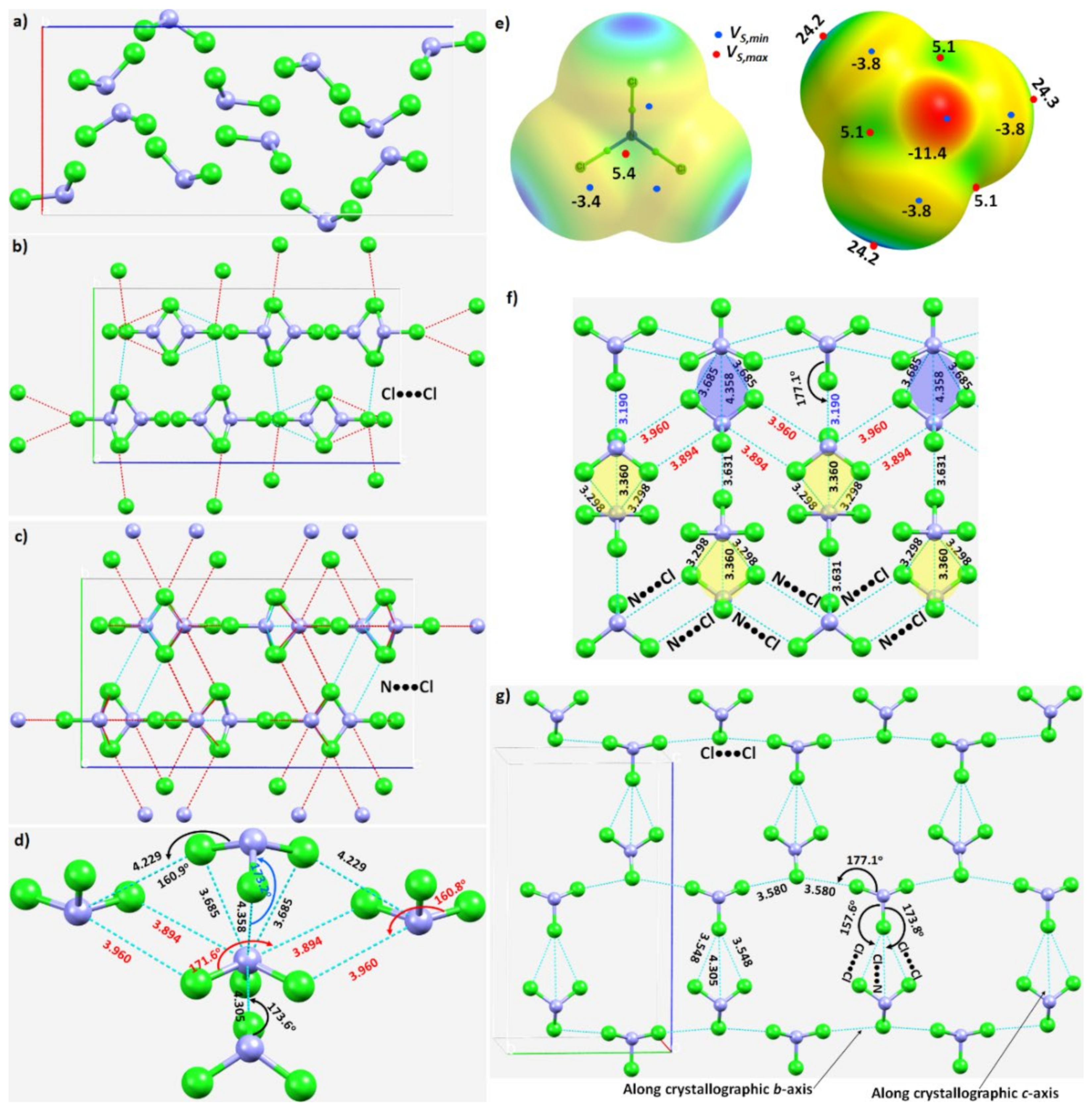
Figure 5. (a) The unit-cell of the NCl3 crystal (ICSD ref. code: 4034). (b) Illustration of the nature of Cl···Cl intermolecular interactions between the molecular building blocks. (c) Illustration of the nature of the N···Cl interactions. (d) Nature of the local topology of bonding around N in NCl3, showing N is a penta-furcated center. (e) Nature of the reactive sites on the electrostatic surface of the NCl3 molecule responsible for the N···Cl, Cl···N and Cl···Cl interactions, computed with ωB97XD/aug-cc-pVTZ. (f) The nature of various N···Cl and Cl···N interactions in the crystal. (g) The nature of Cl···Cl and Cl···N halogen-bonded interactions in the crystal. Values of bond lengths and bond angles in Å and degrees, respectively.
The N–Cl···N and N–Cl···Cl intermolecular interactions holding the NCl3 molecules together in the crystal can be rationalized by referring to Figure 5b,c, respectively. The extent to which covalently bound N in the NCl3 molecule is engaged with the negative sites on neighboring NCl3 molecules, and producing the observed solid-state structure, is illustrated in Figure 5d. The bonding features are as expected when positive and negative sites on molecular surfaces are in close proximity, inferred from the MESP of NCl3 (Figure 5e).
The pattern of intermolecular interactions between bonded N and Cl in the NCl3 crystal is illustrated in Figure 5f. It is evident that each N donates three σ-holes. Two of these, the attraction between a covalently bonded N in an NCl3 molecule and chlorines on neighboring molecules, generate a zig-zag chain-like pattern. They are inequivalent, in contrast to the analogous interactions observed in the NF3 crystal described above. The r(N···Cl) (∠Cl–N···Cl) for these two contacts are 3.960 Å (160.8°) and 3.894 Å (171.6°), respectively, suggesting a Type-IIa nitrogen bonding topology. The remaining σ-hole bond formed by N, Figure 5d,f, is longer and quasi-linear (r(N···Cl) = 4.358 Å and ∠Cl–N···Cl = 173.2°), and is a result of the packing of molecules in the crystal. As shown in Figure 5d, each N site serves as a penta-furcated center in accepting and donating σ-hole bonds.
The three pnictogen bonds are augmented by σ-centered N–Cl···N and N–Cl···Cl halogen bonds in stabilizing the crystal. These Type-IIa N–Cl···N bonds are highly directional (r(Cl···N) = 3.190 Å and ∠N–Cl···N = 177.1°), and are formed between the σ-hole on the N–Cl bond extension in one molecule and the lone-pair dominated region on N in another interacting molecule (Figure 5g).
The three N···Cl contacts highlighted in yellow in Figure 5f are repeated throughout the crystal. Two of them are equivalent (r(N···Cl) = 3.298 Å) and the other slightly longer (r(N···Cl) = 3.360 Å). They are significantly bent, with ∠Cl–N···Cl of 140.3° and 140.1°, respectively. They are enforced by the attraction between the positive site in the central region of the triangular face formed by three Cl atoms in the NCl3 molecule and the lone-pair dominated negative site on the N of a neighboring molecule. One might characterize this as an N(π)···N(π) pnictogen bond, consistent with the surface extrema revealed by the MESP model (Figure 5e).
Figure 5g shows the pattern of occurrence of Type-IIa N–Cl···Cl halogen bonds. Those having a Cl···Cl bond distance (and ∠N–Cl···Cl) of 3.580 Å (168.4°) are more directional than those with the corresponding values of 3.548 Å (157.6°). Indeed, they are shorter and less directional than Cl···N halogen bonds with bond distances (angles) of 4.305 Å (173.8°), Figure 5g. There are numerous Cl···Cl contacts present in the crystal (not shown).
References
- Arunan, E.; Desiraju, G.R.; Klein, R.A.; Sadlej, J.; Scheiner, S.; Alkorta, I.; Clary, D.C.; Crabtree, R.H.; Dannenberg, J.J.; Hobza, P.; et al. Definition of the hydrogen bond (IUPAC Recommendations 2011). Pure Appl. Chem. 2011, 83, 1637–1641.
- Desiraju, G.R.; Shing Ho, P.; Kloo, L.; Legon, A.C.; Marquardt, R.; Metrangolo, P.; Politzer, P.; Resnati, G.; Rissanen, K. Definition of the halogen bond (IUPAC Recommendations 2013). Pure Appl. Chem. 2013, 85, 1711–1713.
- Aakeroy, C.B.; Bryce, D.L.; Desiraju, R.G.; Frontera, A.; Legon, A.C.; Nicotra, F.; Rissanen, K.; Scheiner, S.; Terraneo, G.; Metrangolo, P.; et al. Definition of the chalcogen bond (IUPAC Recommendations 2019). Pure Appl. Chem. 2019, 91, 1889–1892.
- IUPAC Project: Categorizing Chalcogen, Pnictigen, and Tetrel Bonds, and Other Interactions Involving Group 14–16 Elements. Available online: https://iupac.org/projects/project-details/?project_nr=2016-001-2-300 (accessed on 31 January 2022).
- Bakker, D.J.; Peters, A.; Yatsyna, V.; Zhaunerchyk, V.; Rijs, A.M. Far-Infrared Signatures of Hydrogen Bonding in Phenol Derivatives. J. Phys. Chem. Lett. 2016, 7, 1238–1243.
- Vasylyeva, V.; Catalano, L.; Nervi, C.; Gobetto, R.; Metrangolo, P.; Resnati, G. Characteristic redshift and intensity enhancement as far-IR fingerprints of the halogen bond involving aromatic donors. CrystEngComm 2016, 18, 2247–2250.
- Hardin, A.E.S.; Ellington, T.L.; Nguyen, S.T.; Rheingold, A.L.; Tschumper, G.S.; Watkins, D.L.; Hammer, N.I. A Raman Spectroscopic and Computational Study of New Aromatic Pyrimidine-Based Halogen Bond Acceptors. Inorganics 2019, 7, 119.
- Messina, M.T.; Metrangolo, P.; Navarrini, W.; Radice, S.; Resnati, G.; Zerbi, G. Infrared and Raman analyses of the halogen-bonded non-covalent adducts formed by α,ω-diiodoperfluoroalkanes with DABCO and other electron donors. J. Mol. Struct. 2000, 524, 87–94.
- Shen, Q.J.; Jin, W.J. Strong halogen bonding of 1,2-diiodoperfluoroethane and 1,6-diiodoperfluorohexane with halide anions revealed by UV-Vis, FT-IR, NMR spectroscopes and crystallography. Phys. Chem. Chem. Phys. 2011, 13, 13721–13729.
- Widner, D.L.; Robinson, E.R.; Perez, A.B.; Vang, H.G.; Thorson, R.A.; Driscoll, Z.L.; Giebel, S.M.; Berndt, C.W.; Bosch, E.; Speetzen, E.D.; et al. Comparing Strong and Weak Halogen Bonding in Solution: 13C NMR, UV/Vis, Crystallographic, and Computational Studies of an Intramolecular Model. Eur. J. Org. Chem. 2017, 2017, 5739–5749.
- Hakkert, S.B.; Gräfenstein, J.; Erdelyi, M. The 15N NMR chemical shift in the characterization of weak halogen bonding in solution. Faraday Discuss. 2017, 203, 333–346.
- Gomila, R.M.; Frontera, A. Charge assisted halogen and pnictogen bonds: Insights from the Cambridge Structural Database and DFT calculations. CrystEngComm 2020, 22, 7162–7169.
- De Azevedo Santos, L.; Hamlin, T.A.; Ramalho, T.C.; Bickelhaupt, F.M. The pnictogen bond: A quantitative molecular orbital picture. Phys. Chem. Chem. Phys. 2021, 23, 13842–13852.
- Fanfrlík, J.; Zierkiewicz, W.; Švec, P.; Růžičková, Z.; Řezáč, J.; Michalczyk, M.; Růžička, A.; Michalska, D.; Hobza, P. Pnictogen bonding in pyrazine·PnX5 (Pn = P, As, Sb and X = F, Cl, Br) complexes. J. Mol. Model. 2017, 23, 328.
- Murray, J.S.; Lane, P.; Clark, T.; Riley, K.E.; Politzer, P. σ-Holes, π-holes and electrostatically-driven interactions. J. Mol. Model. 2012, 18, 541–548.
- Clark, T.; Hennemann, M.; Murray, J.S.; Politzer, P. Halogen bonding: The σ-hole. J. Mol. Model. 2007, 13, 291–296.
- Wang, H.; Wang, W.; Jin, W.J. σ-Hole Bond vs. π-Hole Bond: A Comparison Based on Halogen Bond. Chem. Rev. 2016, 116, 5072–5104.
- Zhang, Y.; Wang, W. The σ-hole···σ-hole stacking interaction: An unrecognized type of noncovalent interaction. J. Chem. Phys. 2020, 153, 214302.
- Politzer, P.; Murray, J.S. σ-Hole Interactions: Perspectives and Misconceptions. Crystals 2017, 7, 212.
- Mallada, B.; Gallardo, A.; Lamanec, M.; Torre, B.d.l.; Špirko, V.; Hobza, P.; Jelinek, P. Real-space imaging of anisotropic charge of σ-hole by means of Kelvin probe force microscopy. Science 2021, 374, 863–867.
- Politzer, P.; Murray, J.S. σ-holes and π-holes: Similarities and differences. J. Comp. Chem. 2018, 39, 464–471.
- Varadwaj, A.; Varadwaj, P.R.; Jin, B.-Y. Fluorines in tetrafluoromethane as halogen bond donors: Revisiting address the nature of the fluorine’s σ-hole. Int. J. Quantum Chem. 2015, 115, 453–470.
- Varadwaj, P.R.; Varadwaj, A.; Jin, B.-Y. Halogen bonding interaction of chloromethane with several nitrogen donating molecules: Addressing the nature of the chlorine surface σ-hole. Phys. Chem. Chem. Phys. 2014, 16, 19573–19589.
- Ibrahim, M.A.A.; Moussa, N.A.M. Unconventional Type III Halogen···Halogen Interactions: A Quantum Mechanical Elucidation of σ-Hole∙··σ-Hole and Di-σ-Hole Interactions. ACS Omega 2020, 5, 21824–21835.
- Varadwaj, P.R.; Varadwaj, A.; Marques, H.M. Does Chlorine in CH3Cl Behave as a Genuine Halogen Bond Donor? Crystals 2020, 10, 146.
- Foster, S.L.; Bakovic, S.I.P.; Duda, R.D.; Maheshwari, S.; Milton, R.D.; Minteer, S.D.; Janik, M.J.; Renner, J.N.; Greenlee, L.F. Catalysts for nitrogen reduction to ammonia. Nat. Catal. 2018, 1, 490–500.
- Uyanik, M.; Kato, T.; Sahara, N.; Katade, O.; Ishihara, K. High-Performance Ammonium Hypoiodite/Oxone Catalysis for Enantioselective Oxidative Dearomatization of Arenols. ACS Catal. 2019, 9, 11619–11626.
- Hinokuma, S.; Sato, K. Ammonia Combustion Catalysts. Chem. Lett. 2021, 50, 752–759.
- Lamb, K.E.; Dolan, M.D.; Kennedy, D.F. Ammonia for hydrogen storage; A review of catalytic ammonia decomposition and hydrogen separation and purification. Int. J. Hydrogen Energy 2019, 44, 3580–3593.
- US Geological Survey. Mineral Commodity Summaries 2020; US Geological Survey: Reston, VA, USA, 2020.
- MacFarlane, D.R.; Cherepanov, P.V.; Choi, J.; Suryanto, B.H.R.; Hodgetts, R.Y.; Bakker, J.M.; Ferrero Vallana, F.M.; Simonov, A.N. A Roadmap to the Ammonia Economy. Joule 2020, 4, 1186–1205.
- Ogasawara, K.; Nakao, T.; Kishida, K.; Ye, T.-N.; Lu, Y.; Abe, H.; Niwa, Y.; Sasase, M.; Kitano, M.; Hosono, H. Ammonia Decomposition over CaNH-Supported Ni Catalysts via an NH2−-Vacancy-Mediated Mars–van Krevelen Mechanism. ACS Catal. 2021, 11, 11005–11015.
- Mukherjee, S.; Devaguptapu, S.V.; Sviripa, A.; Lund, C.R.F.; Wu, G. Low-temperature ammonia decomposition catalysts for hydrogen generation. Appl. Catal. B Environ. 2018, 226, 162–181.
- Rouwenhorst, K.H.R.; Engelmann, Y.; van ‘t Veer, K.; Postma, R.S.; Bogaerts, A.; Lefferts, L. Plasma-driven catalysis: Green ammonia synthesis with intermittent electricity. Green Chem. 2020, 22, 6258–6287.
- Gini, A.; Paraja, M.; Galmés, B.; Besnard, C.; Poblador-Bahamonde, A.I.; Sakai, N.; Frontera, A.; Matile, S. Pnictogen-bonding catalysis: Brevetoxin-type polyether cyclizations. Chem. Sci. 2020, 11, 7086–7091.
- Humeniuk, H.V.; Gini, A.; Hao, X.; Coelho, F.; Sakai, N.; Matile, S. Pnictogen-Bonding Catalysis and Transport Combined: Polyether Transporters Made In Situ. JACS Au 2021, 1, 1588–1593.
- Paraja, M.; Gini, A.; Sakai, N.; Matile, S. Pnictogen-Bonding Catalysis: An Interactive Tool to Uncover Unorthodox Mechanisms in Polyether Cascade Cyclizations. Chem. A Eur. J. 2020, 26, 15471–15476.
- Benz, S.; Poblador-Bahamonde, A.I.; Low-Ders, N.; Matile, S. Catalysis with Pnictogen, Chalcogen, and Halogen Bonds. Angew. Chem. Int. Ed. 2018, 57, 5408–5412.
- Taylor, M.S. Anion recognition based on halogen, chalcogen, pnictogen and tetrel bonding. Coord. Chem. Rev. 2020, 413, 213270.
- Qiu, J.; Song, B.; Li, X.; Cozzolino, A.F. Solution and gas phase evidence of anion binding through the secondary bonding interactions of a bidentate bis-antimony(iii) anion receptor. Phys. Chem. Chem. Phys. 2018, 20, 46–50.
- Legon, A.C. Tetrel, pnictogen and chalcogen bonds identified in the gas phase before they had names: A systematic look at non-covalent interactions. Phys. Chem. Chem. Phys. 2017, 19, 14884–14896.
- Lee, L.M.; Tsemperouli, M.; Poblador-Bahamonde, A.I.; Benz, S.; Sakai, N.; Sugihara, K.; Matile, S. Anion Transport with Pnictogen Bonds in Direct Comparison with Chalcogen and Halogen Bonds. J. Am. Chem. Soc. 2019, 141, 810–814.
- Moaven, S.; Andrews, M.C.; Polaske, T.J.; Karl, B.M.; Unruh, D.K.; Bosch, E.; Bowling, N.P.; Cozzolino, A.F. Triple-Pnictogen Bonding as a Tool for Supramolecular Assembly. Inorg. Chem. 2019, 58, 16227–16235.
- Mahmudov, K.T.; Gurbanov, A.V.; Aliyeva, V.A.; Resnati, G.; Pombeiro, A.J.L. Pnictogen bonding in coordination chemistry. Coord. Chem. Rev. 2020, 418, 213381.
- Mahmudov, K.T.; Huseynov, F.E.; Aliyeva, V.A.; Guedes da Silva, M.F.C.; Pombeiro, A.J.L. Noncovalent Interactions at Lanthanide Complexes. Chem. Eur. J. 2021, 27, 14370–14389.
- Liu, C.; Shin, J.; Son, S.; Choe, Y.; Farokhzad, N.; Tang, Z.; Xiao, Y.; Kong, N.; Xie, T.; Kim, J.S.; et al. Pnictogens in medicinal chemistry: Evolution from erstwhile drugs to emerging layered photonic nanomedicine. Chem. Soc. Rev. 2021, 50, 2260–2279.
- Fanfrlík, J.; Hnyk, D. Dihalogen and Pnictogen Bonding in Crystalline Icosahedral Phosphaboranes. Crystals 2018, 8, 390.
- Sobalev, S.; Matveychuk, Y.; Bartashevich, E. Features of the Pnictogen Bonds Formed by Neighboring Nitro Groups in Crystals. Bull. South Ural State Univ. Chem. 2019, 11, 66–75.
- Frontera, A.; Bauza, A. On the Importance of Pnictogen and Chalcogen Bonding Interactions in Supramolecular Catalysis. Int. J. Mol. Sci. 2021, 22, 12550.
- Shukla, R.; Chopra, D. Chalcogen and pnictogen bonds: Insights and relevance. Curr. Sci. 2021, 120, 1848–1853.
- Varadwaj, A.; Varadwaj, P.R.; Jin, B.-Y. Can an entirely negative fluorine in a molecule, viz. perfluorobenzene, interact attractively with the entirely negative site (s) on another molecule (s)? Like liking like! RSC Adv. 2016, 6, 19098–19110.
- Varadwaj, P.R.; Cukrowski, I.; Marques, H.M. DFT-X3LYP Studies on the Coordination Chemistry of Ni2+. Part 1: Six Coordinate 2+ Complexes. J. Phys. Chem. A 2008, 112, 10657–10666.
- Varadwaj, P.R.; Marques, H.M. The physical chemistry of coordinated aqua-, ammine-, and mixed-ligand Co2+ complexes: DFT studies on the structure, energetics, and topological properties of the electron density. Phys. Chem. Chem. Phys. 2010, 12, 2126–2138.
- Murray, J.S.; Politzer, P. Can Counter-Intuitive Halogen Bonding Be Coulombic? ChemPhysChem 2021, 22, 1201–1207.
- Chandra, S.; Suryaprasad, B.; Ramanathan, N.; Sundararajan, K. Nitrogen as a pnicogen? Evidence for π-hole driven novel pnicogen bonding interactions in nitromethane–ammonia aggregates using matrix isolation infrared spectroscopy and ab initio computations. Phys. Chem. Chem. Phys. 2021, 23, 6286–6297.
- Turnbull, R.; Hanfland, M.; Binns, J.; Martinez-Canales, M.; Frost, M.; Marqués, M.; Howie, R.T.; Gregoryanz, E. Unusually complex phase of dense nitrogen at extreme conditions. Nat. Commun. 2018, 9, 4717.
- Hanfland, M.; Lorenzen, M.; Wassilew-Reul, C.; Zontone, F. Structures of Molecular Nitrogen at High Pressures. Rev. High Press. Sci. Tecnol. 1998, 7, 787–789.
- Vos, W.L.; Finger, L.W.; Hemley, R.J.; Hu, J.Z.; Mao, H.K.; Schouten, J.A. A high-pressure van der Waals compound in solid nitrogen-helium mixtures. Nature 1992, 358, 46–48.
- Venables, J.A.; English, C.A. Electron diffraction and the structure of -N2. Acta Cryst. B 1974, 30, 929–935.
- Schuch, A.F.; Mills, R.L. Crystal Structures of the Three Modifications of Nitrogen 14 and Nitrogen 15 at High Pressure. J. Chem. Phys. 1970, 52, 6000–6008.
- Alvarez, S. A cartography of the van der Waals territories. Dalton Trans. 2013, 42, 8617–8636.
- Mills, R.L.; Olinger, B.; Cromer, D.T. Structures and phase diagrams of N2 and CO to 13 GPa by X-ray diffraction. J. Chem. Phys. 1986, 84, 2837–2845.
- Stinton, G.W.; Loa, I.; Lundegaard, L.F.; McMahon, M.I. The crystal structures of δ and δ∗ nitrogen. J. Chem. Phys. 2009, 131, 104511.
- Bader, R.F. Atoms in Molecules: A Quantum Theory; Oxford University Press: Oxford, UK, 1990.
- Pritchard, B.P.; Altarawy, D.; Didier, B.; Gibson, T.D.; Windus, T.L. A New Basis Set Exchange: An Open, Up-to-date Resource for the Molecular Sciences Community. J. Chem. Inf. Model. 2019, 59, 4814–4820.
- Ivlev, S.I.; Conrad, M.; Hoelzel, M.; Karttunen, A.J.; Kraus, F. Crystal Structures of α- and β-Nitrogen Trifluoride. Inorg. Chem. 2019, 58, 6422–6430.
- Varadwaj, A.; Varadwaj, P.R.; Marques, H.M.; Yamashita, K. Revealing Factors Influencing the Fluorine-Centered Non-Covalent Interactions in Some Fluorine-substituted Molecular Complexes: Insights from First-Principles Studies. ChemPhysChem 2018, 19, 1486–1499.
- Kawai, S.; Sadeghi, A.; Xu, F.; Peng, L.; Orita, A.; Otera, J.; Goedecker, S.; Meyer, E. Extended halogen bonding between fully fluorinated aromatic molecules. ACS Nano 2015, 9, 2574–2583.
- Varadwaj, A.; Varadwaj, P.R.; Marques, H.M.; Yamashita, K. Comment on “Extended Halogen Bonding between Fully Fluorinated Aromatic Molecules: Kawai et al., ACS Nano, 2015, 9, 2574–2583”. CondMat Public Archive. Available online: https://arxiv.org/ftp/arxiv/papers/1802/1802.09995.pdf (accessed on 12 October 2021).
- Varadwaj, P.R.; Varadwaj, A.; Jin, B.-Y. Unusual bonding modes of perfluorobenzene in its polymeric (dimeric, trimeric and tetrameric) forms: Entirely negative fluorine interacting cooperatively with entirely negative fluorine. Phys. Chem. Chem. Phys. 2015, 17, 31624–31645.
- Hartl, H.; Schöner, J.; Jander, J.; Schulz, H. Die Struktur des festen Stickstofftrichlorids (−125 °C). Z. Anorg. Allg. Chem. 1975, 413, 61–71.
More