The high gain beam steering antennas are widely used in 5G wireless mobile communications, radio frequency (RF) wireless power transmission, and satellite communications. In order to obtain high gain and beam steering characteristics, traditionally, antennas of the same type as phased array antennas, reflectarray antennas, and parabolic antennas have been designed. The transmitarray (TA) has attracted more and more interest from researchers due to its low profile, affordable cost, lower losses, low design complexity, and ease of fabrication. These have become popular solutions due to their remarkable applications, for instance, in biomedical systems (Brain and Breast Cancer Detection), civil and military radar systems, imaging systems, satellite communications, direct broadcasting services, and 6G/5G communication systems, etc.
- reconfigurable transmitarray
- beam steering
- beamforming
- PIN diodes
- varactor
- MEMS
- dual-band transmitarray
- multi-bit transmitarray
1. Introduction
2. Beam Steering/Beam Forming Principle of Transmitarray
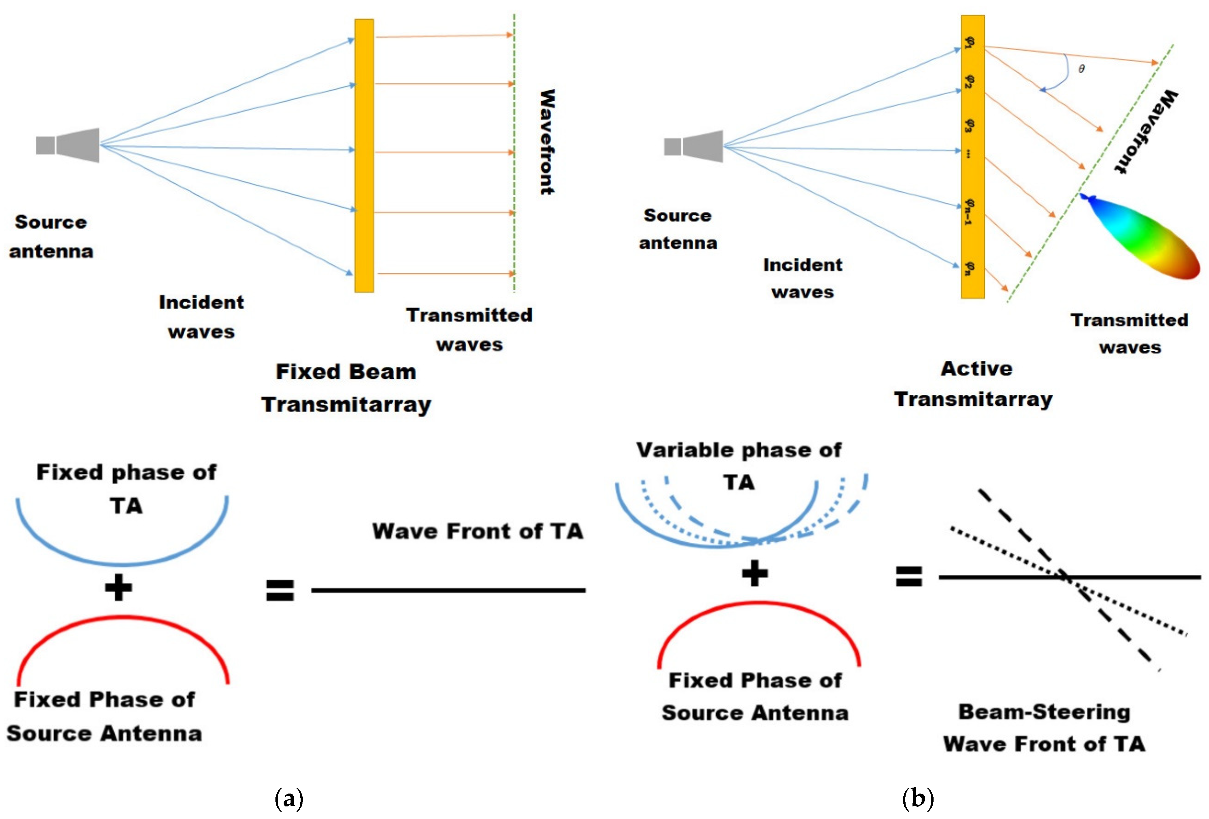
The transmitarray antenna is an antenna that is capable of modifying the radiation pattern of a directional antenna such as a patch antenna or a horn antenna. A transmitarray has the capability of adjusting the wavefront of the source antenna and the incident wave. By using a structure that can adjust the size and phase of the incident wave, the transmission antenna can be used in various fields such as beam steering, beam focusing, and polarization control. Figure 1 shows a typical radiation model of a transmission antenna composed of a source antenna and a transmitarray. A transmitarray is formed by a feed, which is labeled as a source antenna where the source antenna is placed at a distance F from transmitarray. Focal distance (F) is calculated as a tradeoff between spillover losses and an increase in gain, aperture efficiency, and other parameters. The source antenna illuminated by incident wave to the first part of the array is called the receiver. The receiver is directly connected to group of phase shifters to control the beam wave front in the required direction. The other end of the phase shifters are coupled with a transmitter layer, which produces a phase shift in the incident wave that works in transmitter mode. The phase shifter of each unit cell provides γn path difference to the source point to obtain the desired scan angle θ. As shown in Figure 1, the direction of the incident wave is determined by radiation controlled by the transmission phase of the transmitarray. Transmitarrays are generally composed of several resonant unit cells with a spatial periodicity that forms a planar arrangement.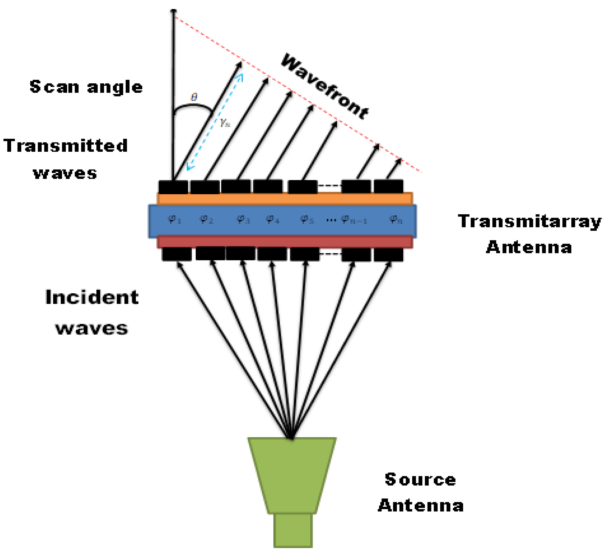
(2)
3. Beam Steering/Beam Forming Using Reconfigurable Components
Several studies are available in the literature [73][74][75][76][77][78][79][80] to demonstrate the operations and functions of transmitarray beam steering. These are realised by utilizing different reconfigurable devices, materials, element designs, and operational parameters. However, every structure needs a requisite to obtain the beam steering/beam forming of the transmitarray antenna. Each transmitarray unit cell must acquire a transmission phase that can be tuned (varied) up to 360 degrees. Moreover, the transmission coefficient should remain constant throughout the operational bandwidth. This section focuses on demonstrating the electronically reconfigurable beam of transmitarray, transmission phase distribution on the transmitarray surface, and the phase shift of each unit cell. Reconfigurable beam steering can be achieved with different techniques. The most prominent one is electronic control accomplished, which is achieved by loading one or more active devices into the resonant elements designed on the unit cell such as (PIN diodes, varactors, and MEMS switches). Other techniques are on the utilization of tunable materials (liquid crystal, microfluidic systems). There is a detail Summary of beam steering reconfigurable transmitarrays with PIN diodes is presents in Table 1.| Ref. | Unit Cell Technique | Phase Control Device | Frequency (GHz) | Polarization | Phase Range | Gain (dBi) | Aperture Efficiency (%) | Band Width | Beam Scanning Capacity |
|---|---|---|---|---|---|---|---|---|---|
| [32] | PCB stacked patch | PIN diode | 5.4 | LP, CP | 1-B1T | 17 | 28.5 | 8.5 | ±50° E and H plane |
| [73] | O-U slot patches | PIN diode | 29 | CP | 1-B1T | 28.5 | 9.5 | 14.6% | ±60° E and H plane |
| [74] | double O-slot patches | PIN diode | 29 | LP | 2-B1T | 19.8 | 15.9 |
3.2. Varactor Diodes
| Ref | Unit Cell Technique | Phase Control Device | Frequency (GHz) | Polarization | Phase Range | Gain (dBi) |
Aperture Efficiency |
Band Width | Beam Steering Capacity | ||||||||||
|---|---|---|---|---|---|---|---|---|---|---|---|---|---|---|---|---|---|---|---|
| [93] | stacked layers | varactor diode | 24.6 | LP | 360° | _ | _ | 1 GHz | ±50° E and H plane | ||||||||||
| [94] | compact varactor based phase shifters | varactor diode | 5.6 | LP | |||||||||||||||
| 16.2% | ±60° E and H plane | ||||||||||||||||||
| 360°, 1-BIT | 15.7 | 33.3 | 16.7% | 60° E and H plane | |||||||||||||||
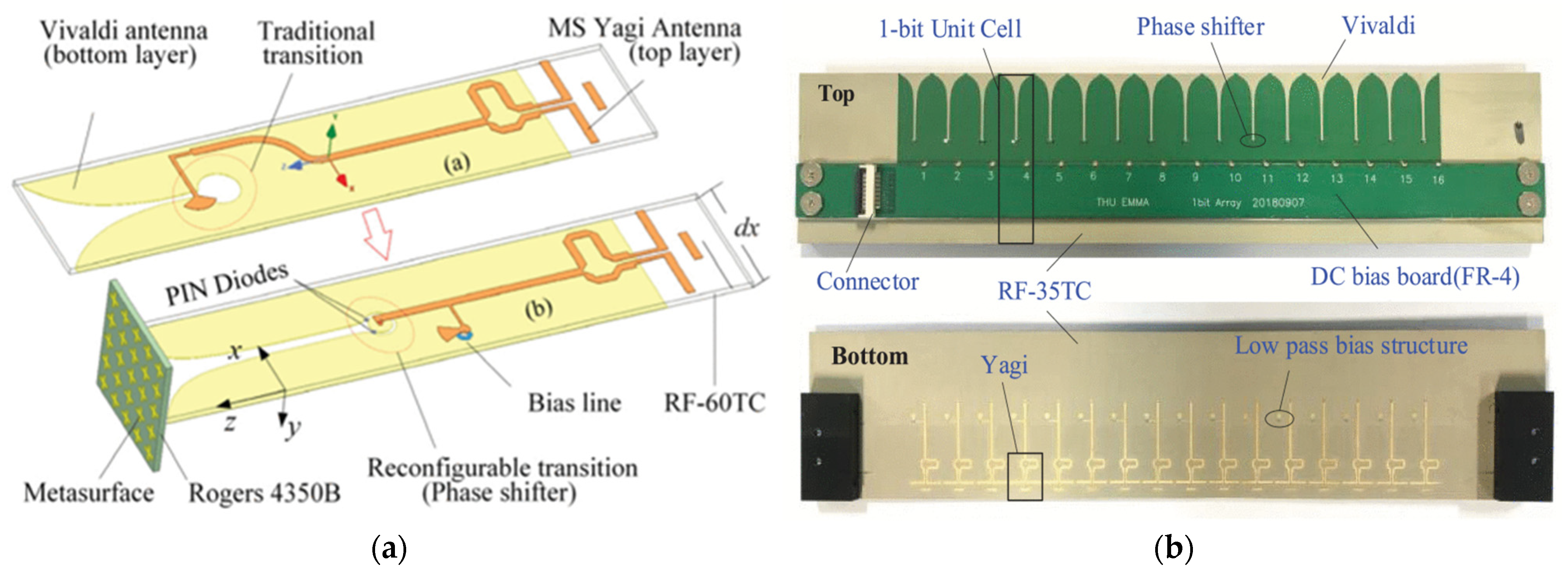
| [95] | FSS | varactor diode | 5.2 | LP | 480° | 20.2 | _ | 13% | ±30° E and H plane | [76] | microstrip Vivaldi | PIN diode | 13.6 | LP | 1-B1T | 22.3 | 25.6 | 1.9% (1-dB) | ±40° E and H plane |
| [79] | coupled slot | PIN diode | 12.5 | LP | 1-B1T | 17 | 14 | 9.6% | ±50° E and H plane | ||||||||||
| [80] | Square ring patch | PIN diode | 5.75 | CP | 1-BIT | 14 | _ | 2.5% | ±30° E and H plane | ||||||||||
| [81] | H and I shape coupling slot | PIN diode | 12.5 | LP | 1-BIT | 17 | 14 | 9.6% | ±50° E and H plane | ||||||||||
| [82] | C-shaped probe-fed patch | PIN diode | 12.1 | LP | 1-B1T | 22.1 | 22.2 | 16% | ±60° E and H plane | ||||||||||
| [83] | split circular rings | PIN diode | 5 | LP | 1-B1T | 16.8 | 18.4 | 17% (1-dB) | ±40° E and H plane | ||||||||||
| [84] | multilayer annular ring patches | PIN diode | 14 | LP | 1-B1T | 20.4 | 33.4 | 33% | ±50° E and H plane |
3.1. PIN Diodes
| [ | ||||||||
| 96 | ||||||||
| ] | ||||||||
| integrated leaky wave | varactor diode | 4.8 | LP | 400° | 15.6 | 34 | 9% | ±45° E and H plane |
References
- Alibakhshikenari, M.; Virdee, B.S.; See, C.H.; Abd-Alhameed, R.A.; Falcone, F.; Limiti, E. High-Isolation Leaky-Wave Array Antenna Based on CRLH-Metamaterial Implemented on SIW with ±30° Frequency Beam-Scanning Capability at Millimetre-Waves. Electronics 2019, 8, 642.
- Alibakhshikenari, M.; Virdee, B.S.; Khalily, M.; Shukla, P.; See, C.H.; Abd-Alhameed, R.; Falcone, F.; Limiti, E. Beam-scanning leaky-wave antenna based on CRLH-metamaterial for millimetre-wave applications. IET Microw. Antennas Propag. 2019, 13, 1129–1133.
- Alibakhshi-Kenari, M.; Andújar, A.; Anguera, J. New compact printed leaky-wave antenna with beam steering. Microw. Opt. Technol. Lett. 2016, 58, 215–217.
- Bia, P.; Caratelli, D.; Mescia, L.; Gielis, J. Analysis and synthesis of supershaped dielectric lens antennas. IET Microw. Antennas Propag. 2015, 9, 1497–1504.
- Hwang, S.; Lee, B.; Kim, D.H.; Park, J.Y. Design of S-band phased array antenna with high isolation using broadside coupled split ring resonator. J. Electromagn. Eng. Sci. 2018, 18, 108–116.
- Rudge, A.; Adatia, N. New class of primary-feed antennas for use with offset parabolic-reflector antennas. Electron. Lett. 1975, 11, 597–599.
- Kock, W. Path-length microwave lenses. Proc. IRE 1949, 37, 852–855.
- McGrath, D. Planar three-dimensional constrained lenses. IEEE Trans. Antennas Propag. 1986, 34, 46–50.
- Pozar, D. Flat lens antenna concept using aperture coupled microstrip patches. Electron. Lett. 1996, 32, 2109–2111.
- Liu, X.; Peng, L.; Liu, Y.F.; Yu, W.S.; Zhao, Q.X.; Jiang, X.; Li, S.M.; Ruan, C. Ultrabroadband All-Dielectric Transmitarray Designing Based on Genetic Algorithm Optimization and 3-D Print Technology. IEEE Trans. Antennas Propag. 2020, 69, 2003–2012.
- Afzal, M.U.; Esselle, K.P.; Lalbakhsh, A. A Methodology to Design a Low-Profile Composite-Dielectric Phase-Correcting Structure. IEEE Antennas Wirel. Propag. Lett. 2018, 17, 1223–1227.
- Yu, W.-S.; Peng, L.; Liu, Y.-F.; Zhao, Q.-X.; Jiang, X.; Li, S.M. An Ultra-wideband and High Aperture Efficiency All-Dielectric Lens Antenna. IEEE Antennas Wirel. Propag. Lett. 2021, 20, 2442–2446.
- Godi, G.; Sauleau, R.; Le Coq, L.; Thouroude, D. Design and Optimization of Three-Dimensional Integrated Lens Antennas with Genetic Algorithm. IEEE Trans. Antennas Propag. 2007, 55, 770–775.
- Fan, Y.; Xu, Y.; Qiu, M.; Jin, W.; Zhang, L.; Lam, E.; Tsai, D.; Lei, D. Phase-controlled metasurface design via optimized genetic algorithm. Nanophotonics 2020, 9, 3931–3939.
- Zhao, X.; Yuan, C.; Liu, L.; Peng, S.; Qiang, Z.; Zhou, H. All-Metal Transmit-array for Circular Polarization Design Using Rotated Cross-Slot Elements for High Power Microwave Applications. IEEE Trans. Antennas Propag. 2017, 65, 3253–3256.
- Chen, G.T.; Jiao, Y.C.; Zhao, G. Novel wideband metal-only transmitarray antenna based on 1-bit polarization rotation element. Int. J. RF Microw. Comput.-Aided Eng. 2020, 30, e22388.
- Abdelrahman, A.H.; Elsherbeni, A.Z.; Yang, F. Transmitarray antenna design using cross-slot elements with no dielectric substrate. IEEE Antennas Wirel. Propag. Lett. 2014, 13, 177–180.
- Zhao, J.; Li, T.; Li, H.; Yang, X.; Zhou, Y.; Mao, W.; Wang, H.; Hu, B.; Zou, H.; Liu, Q. A Novel Planar Mode-Transducing Antenna Based on Metal-Only Transmitarray Surfaces. IEEE Trans. Antennas Propag. 2019, 67, 3762–3773.
- Liu, G.; Wang, H.J.; Jiang, J.S.; Xue, F.; Yi, M.A. high-efficiency transmitarray antenna using double split ring slot elements. IEEE Antennas Wirel. Propag. Lett. 2015, 14, 1415–1418.
- Guerra, A.; Guidi, F.; Clemente, A.; D'Errico, R.; Dussopt, L.; Dardari, D. Application of transmitarray antennas for indoor mapping at millimeter-waves. In Proceedings of the 2015 European Conference on Networks and Communications (EuCNC), Paris, France, 29 June–2 July 2015; IEEE: Piscataway, NJ, USA, 2015.
- Santini, T.; Zhao, Y.; Wood, S.; Krishnamurthy, N.; Kim, J.; Farhat, N.; Alkhateeb, S.; Martins, T.; Koo, M.; Zhao, T.; et al. In-vivo and numerical analysis of the eigenmodes produced by a multi-level Tic-Tac-Toe head transmit array for 7 Tesla MRI. PLoS ONE 2018, 13, e0206127.
- Rappaport, T.S.; Sun, S.; Mayzus, R.; Zhao, H.; Azar, Y.; Wang, K.; Wong, G.; Schulz, J.K.; Samimi, M.; Gutierrez, F. Millimeter Wave Mobile Communications for 5G Cellular: It Will Work! IEEE Access 2013, 1, 335–349.
- Jouanlanne, C.; Clemente, A.; Huchard, M.; Keignart, J.; Barbier, C.; Le Nadan, T.; Petit, L. Wideband Linearly Polarized Transmitarray Antenna for 60 GHz Backhauling. IEEE Trans. Antennas Propag. 2017, 65, 1440–1445.
- Zainud-Deen, S.H.; Hassan, W.; Malhat, H. Near-Field focused folded transmitarray antenna for medical applications. Wirel. Pers. Commun. 2017, 96, 4885–4894.
- Hassanien, A.; Vorobyov, S.A.; Yoon, Y.S.; Park, J.Y. Root-MUSIC based source localization using transmit array interpolation in MIMO radar with arbitrary planar arrays. In Proceedings of the 2013 5th IEEE International Workshop on Computational Advances in Multi-Sensor Adaptive Processing (CAMSAP), Saint Martin, France, 15–18 December 2013; IEEE: Piscataway, NJ, USA, 2013.
- Veljovic, M.J.; Skrivervik, A.K. Circularly Polarized Transmitarray Antenna for CubeSat Intersatellite Links in K-Band. IEEE Antennas Wirel. Propag. Lett. 2020, 19, 1749–1753.
- Chen, Q.; Saifullah, Y.; Yang, G.-M.; Jin, Y.-Q. Electronically reconfigurable unit cell for transmit-reflect-arrays in the X-band. Opt. Express 2021, 29, 1470–1480.
- Li, W.; Wang, Y.; Sun, S.; Shi, X. An FSS-Backed Reflection/Transmission Reconfigurable Array Antenna. IEEE Access 2020, 8, 23904–23911.
- Reis, J.; Al-Daher, R.Z.; Copner, N.; Caldeirinha, R.; Fernandes, T. Two-dimensional antenna beamsteering using metamaterial transmitarray. In Proceedings of the 2015 9th European Conference on Antennas and Propagation (EuCAP), Lisbon, Portugal, 12–17 April 2015; IEEE: Piscataway, NJ, USA, 2015.
- Ali, Q.; Xiao, Y.; Sun, H. 1 BIT Wide-Band Hexagonal Electronically Reconfigurable Unit Cell for Ka-Band Transmit-array. In Proceedings of the 2020 IEEE Asia-Pacific Microwave Conference (APMC), Hong Kong, China, 8–11 December 2020; IEEE: Piscataway, NJ, USA, 2020.
- Tang, J.; Xu, S.; Yang, F.; Li, M. Design of a Wideband Reconfigurable Transmitarrray Element Using a Novel Phase Shifter with Varactors and PIN Diodes. In Proceedings of the 2019 International Symposium on Antennas and Propagation (ISAP), Xi’an, China, 27–30 October 2019; IEEE: Piscataway, NJ, USA, 2019.
- Ali, Q.; Xiao, Y.; Bin, X.; Sun, H.J. 1 BIT Fractal Hexagonal Shape Electronically Reconfigurable Transmit-array Unit Cell for 5G Communication Systems. In Proceedings of the 2021 1st International Conference on Microwave, Antennas & Circuits (ICMAC), Islamabad, Pakistan, 21–22 December 2021.
- Huang, C.; Pan, W.; Ma, X.; Zhao, B.; Cui, J.; Luo, X. Using Reconfigurable Transmitarray to Achieve Beam-Steering and Polarization Manipulation Applications. IEEE Trans. Antennas Propag. 2015, 63, 4801–4810.
- Clemente, A.; Dussopt, L.; Reig, B.; Sauleau, R.; Potier, P.; Pouliguen, P. 1-bit mems based reconfigurable unit-cell for transmit-array antennas at x-band frequencies. In Proceedings of the 13th International Symposium on RF MEMS and RF Microsystems (MEMSWAVE 2012), Antalya, Turkey, 2–4 July 2012.
- Perez-Palomino, G.; Carrasco, E.; Cano-Garcia, M.; Hervas, R.; Quintana, X.; Geday, M.A. Design and Evaluation of Liquid Crystal-Based Pixels for Millimeter and Sub-Millimeter Electrically Addressable Spatial Wave Modulators. In Proceedings of the 2019 International Conference on Electromagnetics in Advanced Applications (ICEAA), Granada, Spain, 9–13 September 2019.
- Li, X.; Li, Z.; Wan, C.; Song, S. Design and Analysis of Terahertz Transmitarray Using 1-bit Liquid Crystal Phase Shifter. In Proceedings of the 2020 9th Asia-Pacific Conference on Antennas and Propagation (APCAP), Xiamen, China, 4–7 August 2020; IEEE: Piscataway, NJ, USA, 2020.
- Long, S.A.; Huff, G.H. A fluidic loading mechanism for phase reconfigurable reflectarray elements. IEEE Antennas Wirel. Propag. Lett. 2011, 10, 876–879.
- Malhat, H.A.; Zainud-Deen, S.H.; Gaber, S.M. Circularly polarized graphene based transmitarray for terahertz applications. In Proceedings of the 2014 XXXIth URSI General Assembly and Scientific Symposium (URSI GASS), Beijing, China, 16–23 August 2014; IEEE: Piscataway, NJ, USA, 2014.
- Manzillo, F.F.; Smierzchalski, M.; Reverdy, J.; Clemente, A.A. Ka-band Beam-Steering Transmitarray Achieving Dual-Circular Polarization. In Proceedings of the 2021 15th European Conference on Antennas and Propagation (EuCAP), Online, 22–26 March 2021; IEEE: Piscataway, NJ, USA, 2021.
- Clemente, A. Deliverable D3. 2: Electronically Reconfigurable Antenna; European Commission: Brussels, Belgium, 2017.
- Minatti, G.; Martini, E.; Caminita, F.; Pavone, S.C.; Albani, M.; Toso, G.; Maci, S. Electronically reconfigurable metasurface antennas based on liquid crystal technology. In Proceedings of the 2019 13th European Conference on Antennas and Propagation (EuCAP), Krakow, Poland, 31 March–5 April 2019; IEEE: Piscataway, NJ, USA, 2019.
- Hu, W.; Dickie, R.; Cahill, R.; Gamble, H.; Ismail, Y.; Fusco, V.; Linton, D.; Grant, N.; Rea, S. Liquid Crystal Tunable mm Wave Frequency Selective Surface. IEEE Microw. Wirel. Components Lett. 2007, 17, 667–669.
- Hassan, W.M. Multilayer graphene-only transmitarray antenna (MGOT) for terahertz applications. In Proceedings of the 2017 34th National Radio Science Conference (NRSC), Alexandria, Egypt, 13–16 March 2017.
- Lima, E.B.; Matos, S.A.; Costa, J.R.; Fernandes, C.A.; Fonseca, N.J.G. Circular Polarization Wide-Angle Beam Steering at Ka-Band by In-Plane Translation of a Plate Lens Antenna. IEEE Trans. Antennas Propag. 2015, 63, 5443–5455.
- Rahmati, B.; Hassani, H.R. Low-Profile Slot Transmitarray Antenna. IEEE Trans. Antennas Propag. 2014, 63, 174–181.
- Jiang, M.; Chen, Z.N.; Zhang, Y.; Hong, W.; Xuan, X. Metamaterial-Based Thin Planar Lens Antenna for Spatial Beamforming and Multibeam Massive MIMO. IEEE Trans. Antennas Propag. 2016, 65, 464–472.
- Massaccesi, A.; Dassano, G.; Pirinoli, P. Beam scanning capabilities of a 3d-printed perforated dielectric transmitarray. Electronics 2019, 8, 379.
- Lee, J.G.; Kwon, T.S.; Lee, J.H. Beam pattern reconfigurable circularly polarized transmitarray antenna by rearrangement of sources. Microw. Opt. Technol. Lett. 2019, 61, 999–1003.
- Yeap, S.B.; Qing, X.; Chen, Z.N. 77-GHz dual-layer transmit-array for automotive radar applications. IEEE Trans. Antennas Propag. 2015, 63, 2833–2837.
- Tuloti, S.H.R.; Rezaei, P.; Hamedani, F.T. High-efficient wideband transmitarray antenna. IEEE Antennas Wirel. Propag. Lett. 2018, 17, 817–820.
- Bagheri, M.O.; Hassani, H.R.; Rahmati, B. Dual-band, dual-polarised metallic slot transmitarray antenna. IET Microw. Antennas Propag. 2017, 11, 402–409.
- Chen, L.-W.; Ge, Y.; Bird, T.S. Ultrathin flat microwave transmitarray antenna for dual-polarised operations. Electron. Lett. 2016, 52, 1653–1654.
- Tian, C.; Jiao, Y.-C.; Zhao, G. Circularly polarized transmitarray antenna using low-profile dual-linearly polarized elements. IEEE Antennas Wirel. Propag. Lett. 2016, 16, 465–468.
- Xu, H.X.; Cai, T.; Zhuang, Y.Q.; Peng, Q.; Wang, G.M.; Liang, J.G. Dual-mode transmissive metasurface and its applications in multibeam transmitarray. IEEE Trans. Antennas Propag. 2017, 65, 1797–1806.
- Abdelrahman, A.H.; Nayeri, P.; Elsherbeni, A.Z.; Yang, F. Single-Feed Quad-Beam Transmitarray Antenna Design. IEEE Trans. Antennas Propag. 2016, 64, 953–959.
- Lee, C.; Hoang, T.V.; Chi, S.W.; Lee, S.; Lee, J. Low profile quad-beam circularly polarised antenna using transmissive metasurface. IET Microw. Antennas Propag. 2019, 13, 1690–1698.
- Mailloux, R.J. Phased Array Antenna Handbook; Artech House: Norwood, MA, USA, 2017.
- Reis, J.; Al-Daher, Z.; Copner, N.; Hammoudeh, A.; Caldeirinha, R.; Fernandes, T. Two-dimensional transmitarray beamsteering using stacked tunable metamaterials. In Proceedings of the 2014 Loughborough Antennas and Propagation Conference (LAPC), Loughborough, UK, 10–11 November 2014; IEEE: Piscataway, NJ, USA, 2014.
- Abdelrahman, A.H.; Nayeri, P.; Elsherbeni, A.Z.; Yang, F. Analysis and Design of Transmitarray Antennas. Synthesis Lectures on Antennas; Morgan & Claypool: San Rafael, CA, USA, 2017; Volume 6, pp. 1–175.
- Diaby, F.; Clemente, A.; Dussopt, L.; Sauleau, R.; Pham, K.; Fourn, E. Design of a 3-facet linearly-polarized transmitarray antenna at Ka-band. In Proceedings of the 2018 IEEE International Symposium on Antennas and Propagation & USNC/URSI National Radio Science Meeting, Boston, MA, USA, 8–13 July 2018; IEEE: Piscataway, NJ, USA, 2018.
- Rana, B.; Lee, I.G.; Hong, I.P. Digitally reconfigurable transmitarray with beam-steering and polarization switching capabilities. IEEE Access 2021, 9, 144140–144148.
- Pozar, D.M.; Targonski, S.D.; Syrigos, H. Design of millimeter wave microstrip reflectarrays. IEEE Trans. Antennas Propag. 1997, 45, 287–296.
- Niu, T.; Withayachumnankul, W.; Ung, B.; Menekse, H.; Bhaskaran, M.; Sriram, S.; Fumeaux, C. Experimental demonstration of reflectarray antennas at terahertz frequencies. Opt. Express 2013, 21, 2875–2889.
- Adamidis, G.; Vardiambasis, I. Design and Implementation of a 4 × 4 Butler-Matrix Switched-Beam Antenna Array at the Microwave Communications and Electromagnetic Applications Lab of the Technological Educational Institute of Crete. In Proceedings of the 2005 WSEAS International Conference on Engineering Education (EE′05), Athens, Greece, 8–10 July 2005; pp. 374–379.
- Adamidis, G.; Vardiambasis, I. Smart antenna design and implementation: A simple switched-beam antenna array based on a 8 × 8 Butler-matrix network. In Proceedings of the 10th WSEAS International Conference on Communications, Athens, Greece, 13–15 July 2006; WSEAS: Stevens Point, WI, USA, 2006.
- Adamidis, G.A.; Vardiambasis, I.O.; Ioannidou, M.P.; Kapetanakis, T.N. Design and implementation of single-layer 4 × 4 and 8 × 8 Butler matrices for multibeam antenna arrays. Int. J. Antennas Propag. 2019, 2019, 1645281.
- Capolino, F. Applications of Metamaterials; CRC Press: Boca Raton, FL, USA, 2017.
- Balanis, C.A. Advanced Engineering Electromagnetics; John Wiley & Sons: Hoboken, NJ, USA, 2012.
- Munk, B.A. Frequency Selective Surfaces: Theory and Design; John Wiley & Sons: Hoboken, NJ, USA, 2005.
- Sarabandi, K.; Behdad, N. A frequency selective surface with miniaturized elements. IEEE Trans. Antennas Propag. 2007, 55, 1239–1245.
- Li, M.N.B. Wideband true-time-delay microwave lenses based on metallo-dielectric and all-dielectric lowpass frequency selective surfaces. IEEE Trans. Antennas Propag. 2013, 61, 4109–4119.
- Warren Stutzman, L.; Thiele, G.A. Antenna Theory and Design; John Wiley & Sons: Hoboken, NJ, USA, 2012.
- Clemente, A.; Diaby, F.; Di Palma, L.; Dussopt, L.; Sauleau, R. Experimental validation of a 2-bit reconfigurable unit-cell for transmitarrays at Ka-band. IEEE Access 2020, 8, 114991–114997.
- Di Palma, L.A.C.; Dussopt, L.; Sauleau, R.; Potier, P.; Pouliguen, P. Circularly-polarized reconfigurable transmitarray in Ka-band with beam scanning and polarization switching capabilities. IEEE Trans. Antennas Propag. 2017, 65, 529–540.
- Diaby, F.; Clemente, A.; Sauleau, R.; Pham, K.T.; Dussopt, L. 2 Bit Reconfigurable Unit-Cell and Electronically Steerable Transmitarray at Ka-Band. IEEE Trans. Antennas Propag. 2019, 68, 5003–5008.
- Xiao, Y.; Yang, F.; Xu, S.; Li, M.; Zhu, K.; Sun, H. Design and Implementation of a Wideband 1-Bit Transmitarray Based on a Yagi–Vivaldi Unit Cell. IEEE Trans. Antennas Propag. 2021, 69, 4229–4234.
- Xiao, Y.; Xi, B.; Xiang, M.; Yang, F.; Chen, Z. 1-Bit Wideband Reconfigurable Transmitarray Unit Cell Based on PIN Diodes in Ku-Band. IEEE Antennas Wirel. Propag. Lett. 2021, 20, 1908–1912.
- Wang, Y.; Xu, S.; Yang, F.; Werner, D.H. 1 Bit Dual-Linear Polarized Reconfigurable Transmitarray Antenna Using Asymmetric Dipole Elements with Parasitic Bypass Dipoles. IEEE Trans. Antennas Propag. 2020, 69, 1188–1192.
- Wang, M.; Mo, Y.; Chen, Z.; Shan, K.; Liu, Z.; Feng, J.; Liu, Q.; Li, J. Design of A 4 × 4-Element High-Integrated Planar Pattern Reconfigurable Array Antenna. In Proceedings of the 2021 15th European Conference on Antennas and Propagation (EuCAP), Online, 22–26 March 2021; IEEE: Piscataway, NJ, USA, 2021.
- Kozlov, D.; Munina, I.; Turalchuk, P.; Kirillov, V.; Shitvov, A.; Zelenchuk, D. Characterization of Tiled Architecture for C-Band 1-Bit Beam-Steering Transmitarray. Sensors 2021, 21, 1259.
- Wang, M.; Xu, S.; Yang, F.; Li, M. Design and Measurement of a 1-bit Reconfigurable Transmitarray With Subwavelength H-Shaped Coupling Slot Elements. IEEE Trans. Antennas Propag. 2019, 67, 3500–3504.
- Wang, M.; Xu, S.; Yang, F.; Hu, N.; Xie, W.; Chen, Z. A Novel 1-Bit Reconfigurable Transmitarray Antenna Using a C-Shaped Probe-Fed Patch Element with Broadened Bandwidth and Enhanced Efficiency. IEEE Access 2020, 8, 120124–120133.
- Luo, C.-W.; Zhao, G.; Jiao, Y.-C.; Chen, G.-T.; Yan, Y.-D. Wideband 1 bit Reconfigurable Transmitarray Antenna Based on Polarization Rotation Element. IEEE Antennas Wirel. Propag. Lett. 2021, 20, 798–802.
- Zhai, Z.; Zhao, G.; Sun, H. Design of a Wideband 1-bit 10 × 10 Reconfigurable Transmitarray in Ku Band. In Proceedings of the 2020 International Conference on Microwave and Millimeter Wave Technology (ICMMT), Shanghai, China, 20–23 September 2020; IEEE: Piscataway, NJ, USA, 2020.
- Turalchuk, P.; Munina, I.; Kirillov, V.; Verevkin, A.; Zelenchuk, D. A C-band Transmitarray for Spatial Multiplexing and Diversity Applications. In Proceedings of the 2020 50th European Microwave Conference (EuMC), Utrecht, The Netherlands, 12–14 January 2021.
- Munina, I.; Turalchuk, P.; Verevkin, A.; Kirillov, V.; Zelenchuk, D.; Shitvov, A. A study of C-band 1-bit reconfigurable dual-polarized transmitarray. In Proceedings of the 2019 13th European Conference on Antennas and Propagation (EuCAP), Krakow, Poland, 31 March–5 April 2019; IEEE: Piscataway, NJ, USA, 2019.
- Lau, J.Y.; Hum, S.V. Analysis and characterization of a multipole reconfigurable transmitarray element. IEEE Trans. Antennas Propag. 2010, 59, 70–79.
- Rotshild, D.; Rahamim, E.; Abramovich, A. Innovative Reconfigurable Metasurface 2-D Beam-Steerable Reflector for 5G Wireless Communication. Electronics 2020, 9, 1191.
- Sun, Y.; Li, Z.; Zhu, W.; Ji, Z.; Wang, Q. New steerable antenna with controllable metamaterial. In Proceedings of the 2012 9th European Radar Conference, Amsterdam, The Netherlands, 31 October–2 November 2012; IEEE: Piscataway, NJ, USA, 2012.
- Jiang, T.; Wang, Z.; Li, D.; Pan, J.; Zhang, B.; Huangfu, J.; Salamin, Y.; Li, C.; Ran, L. Low-DC voltage-controlled steering-antenna radome utilizing tunable active metamaterial. IEEE Trans. Microw. Theory Tech. 2011, 60, 170–178.
- Russo, I.; Gaetano, D.; Boccia, L.; Amendola, G.; Di Massa, G. Investigation on the transmission beam-steering capabilities of tunable impedance surfaces. In Proceedings of the 2009 European Microwave Conference (EuMC), Rome, Italy, 29 September–1 October 2009; IEEE: Piscataway, NJ, USA, 2009.
- Padilla, P.; Muñoz-Acevedo, A.; Castañer, M.S.; Sierra-Pérez, M. Electronically Reconfigurable Transmitarray at Ku Band for Microwave Applications. IEEE Trans. Antennas Propag. 2010, 58, 2571–2579.
- Frank, M.; Lurz, F.; Weigel, R.; Koelpin, A. Electronically reconfigurable 6 × 6 element transmitarray at K-band based on unit cells with continuous phase range. IEEE Antennas Wirel. Propag. Lett. 2019, 18, 796–800.
- Tang, J.; Xu, S.; Yang, F.; Li, M. Design and Measurement of a Reconfigurable Transmitarray Antenna with Compact Varactor-based Phase Shifters. IEEE Antennas Wirel. Propag. Lett. 2021, 20, 1998–2002.
- Reis, J.R.; Caldeirinha, R.F.S.; Hammoudeh, A.; Copner, N. Electronically reconfigurable FSS-inspired transmitarray for 2-D beamsteering. IEEE Trans. Antennas Propag. 2017, 65, 4880–4885.
- Nicholls, J.G.; Hum, S.V. Full-space electronic beam-steering transmitarray. IEEE Trans. Antennas Propag. 2016, 64, 3410–3422.
- Frank, M.; Weigel, R.; Koelpin, A. Design of a 24 GHz reconfigurable transmitarray element with continuous phase range. In Proceedings of the 2017 11th European Conference on Antennas and Propagation (EUCAP), Paris, France, 19–24 March 2017; IEEE: Piscataway, NJ, USA, 2017.
- Reis, J.R.; Vala, M.; Oliveira, T.E.; Fernandes, T.R.; Caldeirinha, R.F.S. Metamaterial-Inspired Flat Beamsteering Antenna for 5G Base Stations at 3.6 GHz. Sensors 2021, 21, 8116.