Your browser does not fully support modern features. Please upgrade for a smoother experience.
Please note this is a comparison between Version 1 by Kifayat Ullah and Version 2 by Vivi Li.
The permanent magnet synchronous motor (PMSM) is a highly efficient energy saving machine. Due to its simple structural characteristics, good heat radiation capability, and high efficiency, PMSMs are gradually replacing AC induction motors in many industrial applications. The PMSM has a nonlinear system and lies on parameters that differ over time with complex high-class dynamics. To achieve the excessive performance operation of a PMSM, it essentially needs a speed controller for providing accurate speed tracking, slight overshoot, and robust disturbance repulsion.
- robust speed controller
- PMSM speed regulation
- H∞ robust control
- SMC control
- current controller
1. Introduction
The permanent magnet synchronous motor (PMSM) has outstanding advantages over brush-type motors and is progressively replacing induction motors in many fields because of their benefits, i.e., simple structure, fast dynamic response, high efficiency, high air-gap flux density, and high torque-to-inertia ratio [1]. Due to their vast application prospects, these kinds of motors are broadly used for operation in low and medium power applications. Furthermore, they are used in high-performance electric drives such as electric vehicles, robotics, aeronautical spaceframes, and machine tools [2][3][2,3]. However, the motor model is nonlinear and sensitive to many uncertainties inside and outside the speed control system during operation, making it difficult for the conventional PI control topology to convene the excessive performance control requirements of the system. Therefore, the question of how to suppress the uncertainty of the speed control system to improve the robustness of the system has become a hotspot for scholars [3][4][3,4].
Since the discovery of AC motors for speed regulation, vector control methods are the most popular, and among these methods, direct torque control (DTC) [5][6][5,6] and field-oriented control (FOC) are commonly used [7][8][7,8]. Due to the rapid and full decoupling control of torque and flux, the FOC has been widely used in PMSM motors. In the FOC method, due to their simple design structure, proportional integration (PI) controllers are typically implemented for current and speed control [9]. PI controller gain is usually determined by nominal motor parameters to assemble motor performance specifications [10]. Based on the specified model parameters and time separation assumptions, there is no guarantee of stability if there is uncertainty, load changes, or input saturation constraints. However, where high performance and precision are required, this type of controller is not applicable [11][12][11,12].
For PMSM speed control, the control structure typically uses cascade control loops, including an external speed control loop and two internal current loops [13][14][13,14]. The benefits of the cascading control topology are enhanced disturbance resistance and superior point of tuning response performance [15]. In speed current cascading control, the relationship between the output speed and the four-axis reference current is usually defined by the first-order model. However, given that closed-loop performance may decline due to the disappearance of the relative difference in control cycles between the two loops, a second-order model relationship is also proposed [8][16][8,16]. For high-speed PMSM applications, the integration speed and current controller have been used to address the nonlinear coupling between speed and current. In [17], the authors describe the particle swarm optimization (PSO) technique for the speed control of sensorless PMSM motors.
Therefore, many advanced nonlinear control topologies have been developed in recent years to progress the speed regulation performance of PMSM motors in different applications. These methods include neural network control [18], backstepping control [19], automatic disturbance rejection control [20], fuzzy logic control (FLC) [21], predictive control [5], artificial intelligence-incorporated control [22], sliding mode control (SMC) [23], adaptive control [24], variable structure control (VSC) [25], predictive current control (PCC) [20], disturbance observer (DOB) [26], and extended state observer (ESO) [27][28][27,28]. Furthermore, for the speed regulation of the PMSM, as alternative to the conventional PI control method, H∞ control is in operational use. In H∞ control, external disturbances are assumed to be indeterminate parameters with bounded energy [29]. A robust speed controller based on mixed sensitivity can be used to progress the speed control for each molding in PMSM systems, as in [30][31][30,31]. An adaptive control scheme with a pre-determined H∞ property is implemented for the PMSM control in [32]. Using the robust control principle based on signal compensation, the design method of the robust speed control system with PMSM is proposed in [33]. To comprehend PMSM speed control, a robust predictive controller is proposed [34]. Several of these methods have been used successfully in practical applications.
2. H∞ Robust Control
Hamilton–Jacobi Inequality (HJI) system theory provides several possible control techniques for the academic circles of nonlinear disciplines and has attracted great devotion from PMSM nonlinear system scholars [35]. In the currentr study, several main control approaches to robust control are developed, such as quantitative feedback theory, Kharitonov, H∞, μ theory, and Lyapunov [36]. The H∞ robust current control strategy based on (HJI) is proposed in [37], which improves the robustness of the current control. This method effectively solves the effect of voltage fluctuation on current control performance, but the robustness of load variation is not ideal. To control the motor drive electromagnetic synchronization, H∞ control is used in [29][38][29,38]. However, some measurement errors still occur in the system, such as fixed space lagging and inertia that can indicate high frequency chatter. The Linear Matrix Inequality (LMI) related theory is applied to the PMSM speed control system in [39]. A robust optimal position control strategy, combined with linear quadratic regulator (LQR) and LMI theory, is proposed, resulting in optimal controller gain to ensure system robustness. The robust H∞ sliding mode control strategy based on LMI is proposed [40], which solves the problem of mismatch interference in the system. Although this control method’s effect is good, there may be changes in the system parameters caused by the controller, as well as system parameters mismatch problems, which will affect the controller’s performance [41]. The decisive controller is designed through an interconnect and damping arrangement based on the main principle of energy formative and port series Hamiltonian systems [42]. In addition, the H∞-based current controller is proposed to suppress the voltage variation of the current loop, which improves the current control robustness [43][44][43,44]. For linear time disguise problems, the Kharitonov and H∞ are used; however, there is lack of theoretical evidence. On a theoretical basis, the Lyapunov method is applicable to self-sufficient nonlinear systems [45]. To efficiently suppress the disturbance of system mismatch, the robust H∞-SMC controller, based on LMI, is proposed in [40][46][40,46]. However, it also provides new ideas for resolving parameter mismatch between the PMSM motor and its control system.2.1. H∞ Robust Current Controller Design
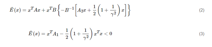
The formula to obtain the H∞ robust current controller is given below [27].

(1)
where h(x) and f(x) are nonlinear. HJI is given below, when E(x) ≥ 0 (E(x*) = 0).
 At the same time, the external disturbance and parameter perturbation are considered, and the state space expression is obtained.
(5)
At the same time, the external disturbance and parameter perturbation are considered, and the state space expression is obtained.
(5) (6)
(6)
 where β>0, ijmoid(s) = 2/(1-e-as)-1, and α>o construct the Lyapunov function as:
 (8)
(8) (9)
By substituting Equations (7) into (9), reswearchers can get the final equation of sliding mode speed control law. A diagram of the basic operation of the H∞ controller is described in Figure 1.
(9)
By substituting Equations (7) into (9), reswearchers can get the final equation of sliding mode speed control law. A diagram of the basic operation of the H∞ controller is described in Figure 1.
(2)
2.2. Design of Robust H∞ Sliding Mode Speed Controller
(3)
2.2. Design of Robust H∞ Sliding Mode Speed Controller
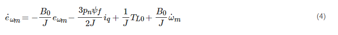
2.2.1. Design of H∞ Sliding Surface
The H∞ slide surface refers to the system state that has robust stability and H∞ disturbance attenuation γ on the slide surface [47]. Rewrite the motion equation of the SPMSM under the d-q rotation coordinate system in the form of an error, that is given below [48]. (4)
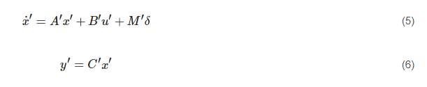
At the same time, the external disturbance and parameter perturbation are considered, and the state space expression is obtained.
(5)
(6)
2.2.2. Robust H∞ Design of the Sliding Mode Speed Control Law
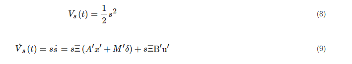
For the system state to reach the slide face within a limited time, set the robust H∞ slip mode speed control law: (7)
where β>0, ijmoid(s) = 2/(1-e-as)-1, and α>o construct the Lyapunov function as:
(8)
(9)
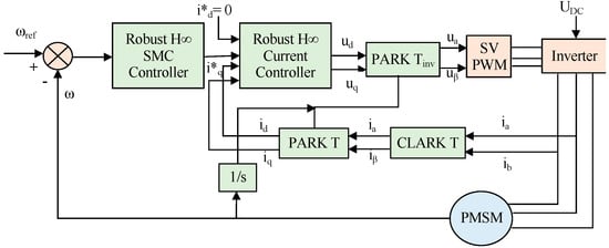
By substituting Equations (7) into (9), reswearchers can get the final equation of sliding mode speed control law. A diagram of the basic operation of the H∞ controller is described in Figure 1.
Figure 1.
Principal diagram of PMSM speed regulation based on H∞ robust controller.