Your browser does not fully support modern features. Please upgrade for a smoother experience.
Please note this is a comparison between Version 1 by Heng Zhang and Version 5 by Lindsay Dong.
Thin-walled composite plates have been widely used as structural components in various engineering applications to bear static and dynamic loads. The vibrations caused by the dynamic loads are transmitted to passengers and precision equipment, which reduces the crew’s comfort, affects normal operations, and shortens the service life of high-precision equipment. There is a rising demand to design optimal composites that have a superior combination of high stiffness and exceptional vibration mitigation capability.
- concurrent topology optimization
- damping composite materials
- dynamic compliance
- homogenization
- composite plates
1. Introduction
Thin-walled composite plates have been widely used as structural components in various engineering applications to bear static and dynamic loads. The vibrations caused by the dynamic loads are transmitted to passengers and precision equipment, which reduces the crew’s comfort, affects normal operations, and shortens the service life of high-precision equipment [1]. There is a rising demand to design optimal composites that have a superior combination of high stiffness and exceptional vibration mitigation capability. Over the past few decades, active and passive methods have been developed to improve the dynamic performance of composite structures [2][3][4][5][2,3,4,5]. Among these methods, incorporating a passive damping material layer into the base plates (i.e., free-layer [6] or constrained-layer [7][8][7,8]) is one of the most efficient, robust, and low-cost methods. Intrinsically, the vibration performance of the composite plates is determined by the properties of the damping materials and their topological arrangements on the base plates. Conventional design practices for damping composite architectures are focused on parameter analysis, in which only a few design variables are considered (i.e., the thickness or the size of the damping layer) [9][10][9,10]. However, these rely heavily on the designers’ intuition and it is hard to obtain the optimal configurations. These challenges are more notable when optimal microstructural damping configurations and macroscopic arrangements are simultaneously pursued.
Topology optimization (TO) [11][12][11,12] is a powerful inverse design technique that does not require predefined shapes. It can be used to generate a free-form optimal configuration that fulfills the functional requirements quantified by the objective functions and constraints. A series of TO methods have been developed to design damping composite structures, which can be broadly classified into two categories: one is to optimize the macrostructure layout of the damping material on the plates [13][14][15][16][13,14,15,16], while the other is focused on optimizing the composite architectures in microscale [17][18][19][20][17,18,19,20] using the homogenization method [21][22][23][24][21,22,23,24]. However, most existing works focus on either the macro- or micro-scale TO. Recent studies show that combining the macrostructure topology optimization with microscale composite material design can significantly improve structural performance. Zhu [25] proposed a concurrent TO strategy to optimize the layout of damping material and the beam size of the lattice core; however, they did not consider the microstructure design problems of the damping layer. Zhang [26] proposed a concurrent TO method to design the free-layer damping structures with a maximum structural modal loss factor. In addition to the damping performance, the vibration response of the structures controlled by dynamic stiffness is equally important. To the authors’ knowledge, so far, limited researches have focused on the multi-scale topology optimization of composite plate structures in a frequency range. In this case, dynamic compliance is often used as the design objective for vibration response design [27][28][29][30][31][32][33][27,28,29,30,31,32,33]. In these studies, dynamic compliance is calculated using proportional damping, which cannot accurately consider the variation of damping due to the change of damping material configurations.
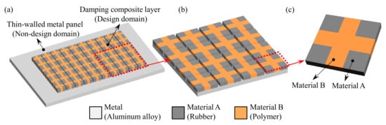
Figure 1. Two-scale composite plate design. (a) A composite plate consists of a metal panel and periodic damping composite. (b) Periodic damping composite. (c) Microstructure of the periodic damping composite.
2. Dynamic Compliance of the Composite Plate
2.1. The Complex Stiffness Model for the Damping Material
A complex stiffness model [26] is used to describe tThe dynamic characteristicest of the damping material, which can be stated as:
where E′ and E″ are the stis paper is orage and loss modulus of the damping material, respectively. η istlined as the loss factor of the damping material. ζ is the imaginary unit, ζ=−1−−−√.
2.2. Complex Frequency Response of the Composite Plate
The momentum equation of a structuraoll system under harmonic excitation can be written as:
wherews: MSection 2 and K are the global mass and stiffness matrices, respectively. K icribes the complgex when the structure contains a damping material with a complex stiffness shown in Equneral numerical computation (1). u is the displacement vector of the macrostructure, f is the magnituhode of the harmonic force, ω is the excitdynation frequency of the harmonic force, and t is time.
The damping characteristic ic cof the metal panel is ignored in this paper since it is negligibly small compared with that opliance of the damping material. The global stiffness matrix of composite structure K is expressed as:
where the superscript “R” and “I” represent the real and imaginary parts, respectively. The subscripts “p” and “v” ding the finitenote the metal panel and the damping composite layer, respectively.
Coelemensidering the free vibration of the composite structure, the complex eigenvalue λr an method the eigenvector. ΦrSection 3 can be expressed as:
where ωr asend ηr are the r-th real eigenvalue and loss factor of the macrostructure. ΦrR and ΦrI are t the mathe real and imaginary parts of the complex eigenvector, respectively. The eigenvector Φ is nortical optimalized to ϕ = {ϕ1, ϕ2,…ϕr,…}.
Converting the governing equation shmown in Equation (2) to the frequency domain leads to:
The sodelution of Equation (6) is:
Based on tthe mode superposition method, the response of structure u isroposed concurrent equatopol to H(ω) when the maognitudey of the harmonic force is a unit load. Then the response can be described as:
whptimization method and ere j is the DoFs of the excitlatibon position, and k is rathe DoFs of the response position. Λ is the number of eigenfrequencies/eigenmodes that are used to calculate the response. Note that the more eigenmodes used, the more accurate results obtained. In this studys the sensitivity analysis on the two scales. In Section 4, Λ = 20 is used.
Using theve non-normalized eigenvector Φ, Equatal numerion (8) can also be expressed as:
whel examples are mr is the r-th modpre mass.
2.3. Dynamic Compliance of the Composite Plate
If the response of the composite plate is obtained, the dynamic compliance can be stated as:
where F is ted to demonstrate the vector of the applied external load. Due to the complex stiffness matrix, the displacement vector u is cffectiveness of the promplex, which is expressed as . Thosed men the dynamic compliance is given by:
where CR anod CI are. the real and Fimaginary parts of the dynamic compliance, respectively. The 2-norm of the dynamic compliance of the composite structures can be defined as:
Acnally, the design rules and cording to Equations (6) and (10), compliance can be stated as:
The displacement vectoclusions are dr is complex, so Equation (13) can be rewritten as:
Fwn inally, dynamic compliance C can be stated as:Section 5.
Figure 1. Two-scale composite plate design. (a) A composite plate consists of a metal panel and periodic damping composite. (b) Periodic damping composite. (c) Microstructure of the periodic damping composite.
According to Equation (15), CR and CI are expressed as: