Your browser does not fully support modern features. Please upgrade for a smoother experience.
Please note this is a comparison between Version 1 by Chen Zhongxian and Version 2 by Jason Zhu.
According to the theory of mechanical vibration, only when the wave power generation system resonates with the ocean wave can the energy of the ocean wave be converted into electric energy to the greatest extent.
Several topics are discussed: the current situation of ocean wave power generation system tests in real ocean waves; the optimization design of linear generator for converting ocean wave energy into electrical energy; some optimization control methods to improve the operational efficiency of ocean wave power generation systems; and the current policy and financial support of ocean wave power generation in some countries.
- wave power generation
- generator design
- Safety
1. Ocean Wave Power Generation System Tests
Despite a wide variety of design methods, and more than 1000 patents having been proposed for ocean wave power generation systems, few prototypes have been tested in real ocean environments [1][14]. Ocean wave power generation systems can be classified into three predominant types according to their location.
1.1. Tested in the Shoreline
An example of the ocean wave power generation system installed on the shoreline is the Wavegen Limpet. The system has a power capacity of 500 kW, and is installed on the island of Islay, Scotland [2][15]. Wavegen Limpet is the world’s first commercial ocean wave power generation system connected to the British National Grid. Figure 1 shows a sketch of Wavegen Limpet, which has two Wells turbine generators. The rise and fall of water column drive air into and out of the wells turbine generator through the pressure chamber. Regardless of the direction of air flow, the well turbine generator can be rotated in the same direction. Therefore, without considering the direction of the generator current, the ocean wave energy can be converted into electrical energy [3][16].
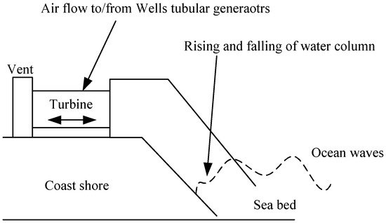
Figure 1. Sketch of Wavegen Limpet.
1.2. Tested near the Shore
A representative prototype of an ocean wave power generation system installed near the shore is Archimedes Wave Swing (AWS). The concept of AWS originated from F. Gardner and H. van Breugel [5][18]. Figure 2 shows the sketch of AWS. Generally, the AWS is a completely submerged cylindrical ocean wave power generation system, the basement part is fixed on the sea bed, and the buoy is connected with the piston of the linear generator. During the operation process of the AWS, the buoy can be pushed down by the wave crest (the pressure of wave crest is larger than the buoyancy of buoy), or it can be pushed up by the wave (the pressure of wave though is smaller than the buoyancy of buoy). Therefore, the buoy can reciprocate with respect to the basement part, thereby driving the piston parts of linear generator to convert ocean wave energy into electrical energy.
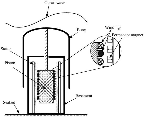
Figure 2. Sketch of AWS.
In order to verify the feasibility of the AWS, some small-scale prototypes of AWSs were tested. In 2004, an AWS pilot plant was installed near the northern shore of Portugal [6][19]. The experimental results indicate that the AWS was proved to be feasible near a shore exposed to ocean waves.
H. Polinder et al. designed and built a double-sided permanent magnet linear synchronous generator (PMLSG) to improve the performance of AWS, as shown in Figure 3. In Figure 3, the permanent magnets is installed on the PMLSG’s stator, the translator (piston) moves inside the stator, and the permanent magnets of the stator generates a varying flux, which induces voltage in the windings of the translator. The PMLSG has the advantages of high force density, reasonable efficiency, and low manufacturing costs [7][20].
Figure 3. Cross-section of PMLSG.
1.3. Tested Offshore
One famous example of ocean wave power generation system installed offshore is the PowerBuoy prototype, designed and constructed by Ocean Power Technologies Inc., and installed off of the northern shore of Spain [8][21]. Pelamis is another offshore ocean wave power generation system, which has also been investigated in many countries, such as Portugal, UK, and China, among other [9][22]. China designed and tested a two-buoy offshore ocean wave power generation system, as shown in Figure 4. In Figure 4, the diameter of the outer buoy is 2.4 m, the diameter of inner buoy is 0.83 m, the linear generator is installed in the inner buoy, and the linear generator’s piston is connected to the outer buoy by a tripod.
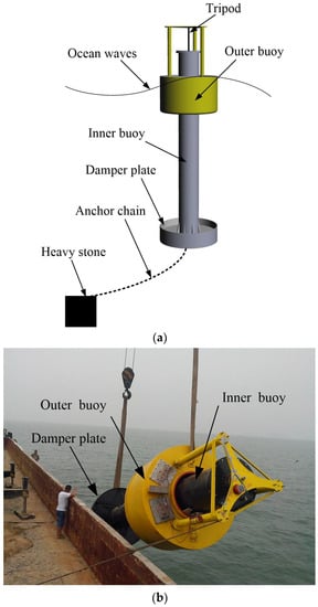
Figure 4.
The two-buoy offshore ocean wave power generation system. (
a
) General scheme; (
b
) Installation process.
Due to the depth below the ocean’s surface being greater, the amplitude of motion of the ocean waves in the vertical direction is smaller. Therefore, the relative motion of two buoys in the vertical direction occurs (the bottoms of the inner buoy and outer buoy below the sea level are different, see Figure 4a), which drives the linear generator to convert ocean wave energy into electrical energy [10][23].
In August, 2014, the two buoys offshore ocean wave power generation system was installed in the East China Sea (see Figure 4b). According to the experimental results, the maximum instantaneous power is 2.3 kW, and the average power is about 1 kW [10][11][23,24].
Besides, another type of offshore ocean wave power generation system is Pelamis, which was designed by the British Ocean Power Delivery Ltd. (Edinburgh, UK), and tested in Agucadoura Wave Park, Portugal [12][8]. Figure 5 shows the structure of Pelamis, which consists of several buoys, hinged joints, generators, and an anchor. During operations, the relative vertical direction motions of buoys were restricted by the hinged joints, and drive the generators to convert ocean wave energy into electrical energy (the generators were installed in the hinged joints). Pelamis has the advantages of high power capture/unit weight, and was the first offshore ocean wave power generation system to convert ocean wave energy into the grid.
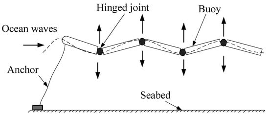
Figure 5. Structure of the Pelamis.
2. Optimal Design of Linear Generator for Ocean Wave Power Generation System
As a part of ocean wave power generation system, the generators play a significant role in the conversion efficiency from wave energy to electrical energy. Usually, there are two kinds of generator that apply to the ocean wave power generation system, namely rotary generators and linear generators [11][13][24,25]. For rotary generators, some transmission systems are required to couple the linear motion of ocean waves and the rotary motion of the rotary generators. For the linear generator, the movement direction between waves and linear generators can be identical (without any linear to rotary conversion devices). In comparison with the conventional rotary generators, high efficiency and easy construction made the linear generator an attractive candidate for an ocean wave power generation system [14][26]. In this section, some linear generators are reviewed.
2.1. Linear Magnetic-Geared Generator
A permanent magnet is an object made from some material—such as iron, nickel, etc.—which can keep its persistent magnetic field for more than 10 years. Therefore, permanent magnet is one of the appropriate materials to produce magnetic source for generators. Figure 6 shows the basic structure of tubular linear magnetic-geared generator. It consists of a linear magnetic gear and a linear permanent magnet generator. Usually, the operation process is that the low-velocity piston reciprocates with the ocean waves by buoy. Then, under the condition of magnetic gear effect, the velocity of the high-velocity piston is amplified correspondingly. Therefore, the tubular linear magnetic-geared generator produces a higher output voltage [15][27]. The modulation rings are made from steel, and fixed between the high-velocity piston and low-velocity piston by epoxy.
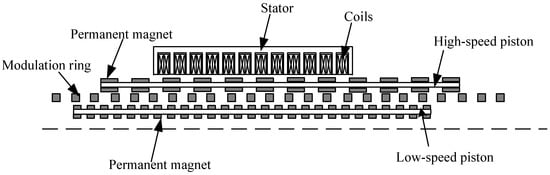
Figure 6. Basic structure of tubular linear magnetic-geared generator.
The theoretical analysis and simulation results indicate that the tubular linear magnetic-geared generator has higher efficiency than conventional rotary generators and linear permanent magnet generators. However, the tubular linear magnetic-geared generator requires some high-precision technology during its production process.
2.2. Linear Switched Reluctance Generator
The linear switched reluctance generator is a special linear generator without a permanent magnet, and it has the advantages of simple structure, good thermal performance, and low cost [16][17][28,29].
Figure 7 shows the sketch of a linear switched reluctance generator, which consists of a stator (static part) and a piston (movable part). Usually, the stator is housed by electrical phase windings, and the piston has no magnetic field source. Since the piston has no magnetic field source, some control methods need to be adopted to make the device as a generator. For example, provided that the linear switched reluctance generator runs at high velocity, the method of position control should be adopted, or the method of pulse width modulation (PWM) chopper control should be to be adopted to keep the generator running at low velocity.
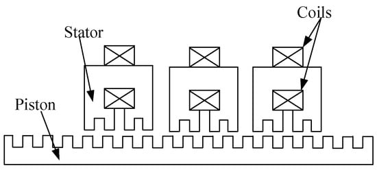
Figure 7.
Sketch of the linear switched reluctance generator.
2.3. Halbach Magnetized Linear Permanent Magnet Generator
A significant advantage of Halbach magnetized linear permanent magnet generator is that the arrangement permanent magnets increase its air-gap flux density. The gap flux density distribution of Halbach magnetized permanent magnet generator is better than that of an ordinary linear permanent magnet generator. Figure 8 illustrates the sketch and prototype of a Halbach magnetized linear permanent magnet generator designed by Southeast University in China [20][32]. In Figure 8a, the Halbach magnetized linear permanent magnet generator adopted assistant teeth to reduce its detent force.
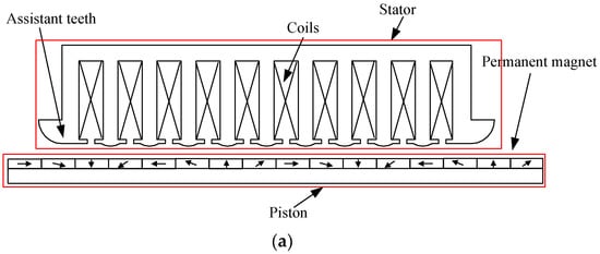
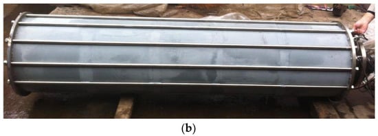
Figure 8. Halbach magnetized linear permanent magnet generator. (a) Sketch; (b) Prototype.
The installation site of the Halbach magnetized linear permanent magnet generator in an ocean wave power generation system is shown in Figure 9. In August 2014, the ocean wave power generation system was installed and tested in the Yellow sea near Lianyungang, China. The experimental results indicate that the ocean wave power generation system has low efficiency in ocean waves [11][24]. The main reason for its low efficiency is that the phase difference between the ocean wave power generation system and the ocean waves. Therefore, some optimization control methods should be proposed to improve the operational efficiency of ocean wave power generation system.
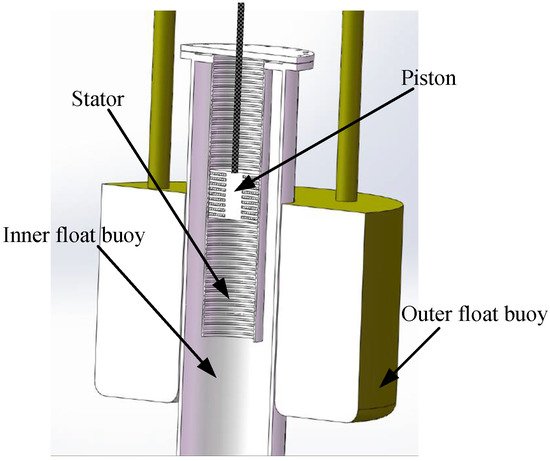
Figure 9. Installation site of Halbach magnetized linear permanent magnet generator.