Your browser does not fully support modern features. Please upgrade for a smoother experience.
Please note this is a comparison between Version 1 by Olga Kudryashova and Version 2 by Vivi Li.
In recent years, there has been explosive growth in interest toward additive manufacturing in many scientific research areas. This can be seen from the increase in the number of publications on this topic, as well as the respective economic indicators; the current additive manufacturing (AM) market size has already exceeded $1300 million. In practice, AM saves time and costs from the design stage to production. Additive manufacturing technologies have been developing for over 30 years. While at the onset, they consisted of relatively simple 3D printing of polymer prototypes, now it is possible to use AM to obtain metallic or non-metallic prototypes or functional products that do not require mechanical post-processing.
- additive manufacturing
- thermite
- high-energy materials
- 3D printing
1. Introduction
The main direction of AM application today is the production of functional products for aerospace and automotive [1][6] industries and biomedicine, as well as manufacturing of electronic devices and measuring equipment, etc. [2][1].
Despite significant advances in AM in recent years, some areas remain problematic. These include AM of high-energy materials (HEM).
Recently, interest has arisen in high-energy nanocomposites. Those make it possible to create miniature energy systems based on nanomaterials with more powerful oxidation kinetics than macroscale materials. Such composites are called “reactive materials” [3][4][7,8], “metastable intermolecular composites” [5][6][9,10], or “pyrolants” [7][8][11,12]. They are prominent in terms of high heat release per unit mass of substance. Furthermore, being nanoscale, they have the potential for precise targeting applications. However, their manufacturing technologies should also differ from conventional ones.
Conventional technologies such as pressing or casting are used for manufacturing products from high-energy materials. These technologies also suffer from imperfections: resulting products may contain pores and cracks [9][13], and some technological stages are unsafe.
Additive manufacturing technologies are the most promising field for the fabrication of products from high-energy nanocomposites since they are commonly and widely used for the creation of nanocomposite products [2][10][1,14]. Additive manufacturing covers a wide range of technologies for the layer-by-layer deposition and synthesis of objects based on computer-designed 3D models. The advantage of such technologies lies in the creation of objects of complex geometry with high resolution, which is important for the use of nanomaterials. However, not all technologies in the AM toolbox are suitable for handling high-energy materials.
Methods for creating planar (2D) structures from reactive materials are outside the scope of this review (unless they are a variation of 3D), and they are considered in detail in [10][14].
2. High-Energy Composite Additive Manufacturing Technologies
2.1. Material Extrusion
Material extrusion is the first and, currently, the most popular additive manufacturing process for a wide range of products in terms of affordability and reliability. Material extrusion is a 3D inkjet printing process whereby the material is fed through a nozzle or jet. This principle of operation is mostly used in inexpensive desktop 3D printers. The requirement for materials for the fabrication of items is the ability to push the material through the nozzle. Any pasty material (sometimes preheated) can be used for “drawing” 2D cross-sections of a certain 3D model.
A variation of the process under consideration is the creation of flat structures, for example, screen printing for pyrotechnic applications [11][16] and Doctor Blade Casting [12][17]. The Doctor Blade method can operate at speeds of up to several meters per minute and is suitable for coating substrates with a very wide range of wet film thicknesses ranging from 20 microns to several hundred microns. Here, an HEM suspension with a dissolved binder is applied to the substrate using a knife with a specific gap (Figure 1). A team from Texas Tech University led by Professor Pantoya has published a series of articles on the fabrication of thermite-based films using this approach [13][14][15][18,19,20].
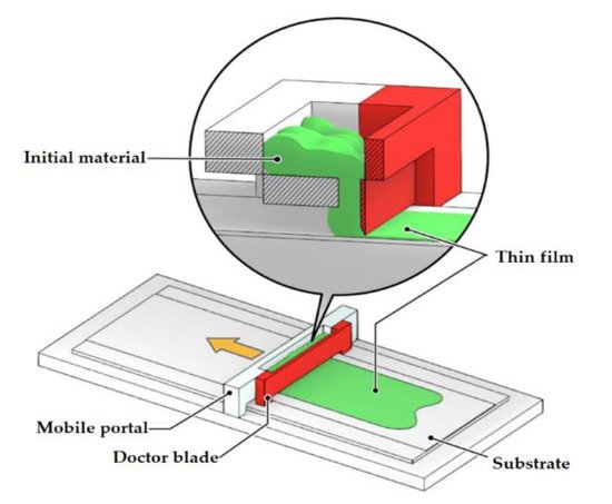
Figure 1. Material extrusion. Fabrication of a thin HEM film using the Doctor Blade Casting method.
The extrusion process is also used for the formation of more complex 3D structures. To this end, the “ink” is applied layer by layer through the hole in the 3D printer head (Figure 2). The respective 3D printing method is called DIW (Direct Ink Writing). Initially, the liquid ink solidifies on the substrate as a result of solvent evaporation or binder deposition, thus creating a volumetric product structure. The minimum size of printed structures can be less than 1 micron, depending on the size of the nozzle and the physicochemical properties of the ink. Thanks to its relative simplicity, DIW is widely used for the fabrication of HEM products [16][17][18][19][20][21][21,22,23,24,25,26].
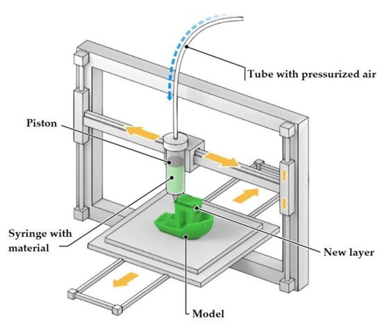
Figure 2. Direct printing method, a schematic diagram.
The pen-type technique is a variation of this method. Here, a specially prepared ink containing a dispersed phase (a nano- or micro-sized aluminum powder, for example) and a binder are used. The ink fills the syringe, and the extrusion process is actuated by pressurized air. The adjustment of air pressure allows for controlling the printing speed and setting up the technology in accordance with the ink viscosity. However, manufacturing articles with a solid content of over 90%, using the pen-type technique, is still a problem. This is because high pressure is required, which also results in the slurry stratification phenomenon, i.e., the separation of the binder from the solids [22][27].
To overcome the limitations associated with high ink viscosity, an ultrasonic technique with high frequency and amplitude oscillations is used [23][28] (up to 30 kHz and 20 µm, respectively). However, ultrasound creates flow hysteresis problems leading to inaccuracies in geometry, nozzle erosion and ink degradation due to high stress.
The main problem of using this technology for the fabrication of products from high-energy compositions is their hazardous nature. Reactive materials are susceptible to ignition, deflagration, detonation or explosion when subjected to shear stress and friction during extrusion as they travel through valve and nozzle assemblies. In addition, it is necessary to meet ink viscosity requirements to create the conditions for the extrusion itself (i.e., material passage through the nozzle) [10][24][14,29]. There are significant difficulties to be overcome, especially when using a suspension with a very high particle content (>80 vol.% of particles). Work [24][29] is devoted to the investigation of a polymer binder used in high-energy compositions from the point of view of the viscosity of the suspension and its suitability for printing.
In general, DIW direct printing technology achieves a relatively high slurry-solid content and appropriate viscosity of the material using special techniques (ultrasound) and careful ink formulation designs, individually designed for each application.
One of the important advantages of this process, as applied to high-energy materials, is the relatively low operating temperatures, which reduce the probability of ignition. The operating temperatures are determined by the physical and chemical characteristics of the material.
2.2. Fused Deposition Modeling (FDM)
FDM is a widely used additive manufacturing technology. It is based on the use of a plastic filament which is deposited in layers through a heated extruder onto a substrate (Figure 3). Typical spatial resolutions achieved by the FDM method lie in the range of 100–500 µm.
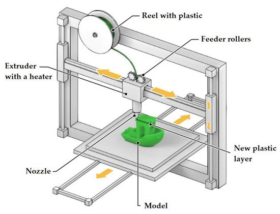
Figure 3. Modeling by layer-by-layer deposition, a schematic diagram.
Today, the FDM printing process has matured to an industrial level, and inexpensive commercial printers are used in the manufacturing process. However, there is little data on the fabrication of high-energy composites based on this technology. The reason for this is obvious: FDM involves a rather high degree of material heating to increase its fluidity. This limits the range of materials that can be printed with FDM to those with a melting point significantly lower than the reaction temperature [25][26][30,31].
Another approach that still does not completely eliminate ignition during printing consists of filling a thermoplastic polymer filament with solid HEM particles [27][32].
The main difference between FDM and DIW is the required feedstock viscosity (for example, 0, 1–103 Pa·s [28][33] for DIW and >103 Pa·s for FDM). The application of FDM to high-energy materials requires the incorporation of high concentrations of reactive particles into the polymer filament to maintain high reaction rates. However, from the point of view of uniform distribution of the components and reduction of material viscosity during printing, lower particle concentrations are recommended [29][34].
Most of the recent works devoted to the use of FDM for the creation of HEM products are focused on the use of poly (vinylidene fluoride) (PVDF), which can serve both as a filament backbone in printing and as an oxidizing agent during the reaction [29][30][31][32][34,35,36,37]. In particular, nano-aluminum (n-Al) and polyvinylidene fluoride (PVDF) are attractive fuel and oxidizing materials due to the high energy density of n-Al as well as high oxidation potential and excellent mechanical properties offered by PVDF [33][38].
Summarizing the research findings obtained on the use of the FDM method for the additive manufacturing of HEM, it can be assumed that this technology has high potential. The main disadvantages of FDM are the limited surface finishing capabilities and precision as well as poor mechanical properties of the products [34][39]. Balancing between the material viscosity and its reactivity also remains a problem as the relatively high temperature of the filament compromises safety during printing.
2.3. Photopolymerization (Laser Stereolithography (SLA), Digital Light Processing (DPL))
Vat Photopolymerization is a 3D printing process that implements a light source to cure liquid photocurable resins (photopolymers). The key difference between the two technologies lies in the type of light source used for curing the material: in SLA (Figure 4), it is ultraviolet light, and in DLP (Figure 5), it is visible light. Normally, the light is projected downwards on the printed material in SLA systems, and from under the printed material (through a transparent surface), in DLP systems.
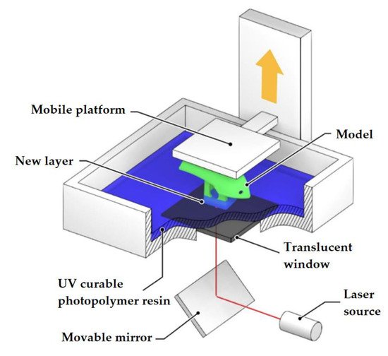
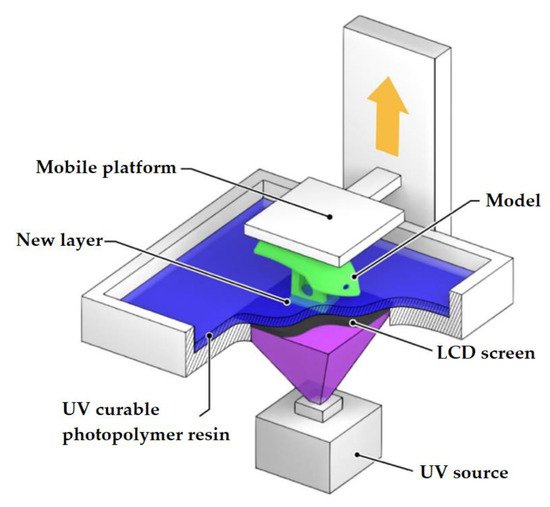
Figure 4. SLA method.
Figure 5. DLP method.
A 3D printer involved in the implementation of vat photopolymerization is equipped with a container with photopolymer resin, which is cured by the light source. SLA printers use a vat with liquid photopolymer resin that is cured by UV radiation. Laser beam processing is done layer by layer. After one layer has been treated, the printer platform is shifted by a distance equal to the layer thickness (0.05–0.15 mm). The resin-filled plate then passes over the cross-section of the item and re-coats it with new material. The next layer is formed on this liquid surface and is joined with the previous one. Thus, an entire 3-dimensional object is formed.
DLP uses visible light projectors such as arc lamps. In this case, each layer of the object being fabricated is projected into a vat of liquid resin, which hardens layer by layer as the platform is raised or lowered. Thanks to this treatment method, DLP is faster than most 3D printing methods.
There are a number of works devoted to SLA application in energy product manufacturing: fuel pellets for hybrid engines [35][40], gun powders [25][36][30,41], compositions based on ammonium perchlorate [37][42] and cannon fuels [38][43]. DLP for energetic materials was used in [39][40][44,45]. Some works reported the use of a combination of DIW and SLA: the composite is first deposited by extrusion and then cured by UV radiation [41][42][46,47].
The use of photopolymerization processes in a vat imposes a number of requirements for the materials [40][45]:
- -
-
All the components must be chemically compatible.
- -
-
The viscosity of the material should be sufficiently low, preferably below 20 Pa⋅s [43][48].
- -
-
The material must be sufficiently stable over time, i.e., sedimentation must not occur for several hours.
- -
-
The material must be sensitive to the wavelength range of the light source used.
- -
-
The material must be promptly cured, preferably within a few seconds.
- -
-
Light penetration into the material (including light scattering) must be limited to provide sufficient resolution in all directions.
- -
-
Once illuminated, the material must have sufficient mechanical strength to withstand transportation, treatment and use.Additional requirements largely depend on the intended use of the printed product. In the case of energy cells, it can be said that the following requirements must be met:
- -
-
The energy resin must not decompose when exposed to the light source used for curing.
- -
-
The energy properties (e.g., heat of explosion, combustion rate, detonation velocity) must be sufficient for the intended use.The main advantages of the photopolymerization methods are high resolution and high performance. The light-induced process eliminates the use of toxic hardeners. The main disadvantage is the need to use polymers that are curable by UV or visible light. This significantly limits the list of materials available for printing.
2.4. Powder Printing (Binder Jetting, Powder Bed Printing)
Two materials are used in printing with this technology: a base material in the form of a powder and a liquid binder. The binder is sprayed by the printer head, and the powder particles stick together to form a solid 3D model (Figure 6). The powder is poured into the first chamber and fed into the second chamber by rolling the required amount of powder with a roller. The powder is poured onto the construction platform lowered to a depth equal to the first layer height. A liquid adhesive binder is fed through the inkjet printer head. After laying one layer, the platform is lowered to a depth equal to the height of the next layer. Then the powder is rolled out of the first chamber into the construction chamber. All subsequent layers are deposited in the same way. After completing the last layer, the 3D model is extracted, and the excess powder is peeled off. Initially, this technology was used to create plaster molds and casting molds.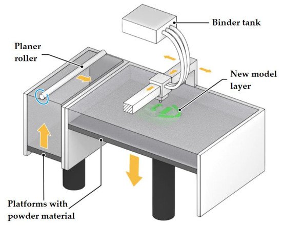 Figure 6. Binder Jetting (Powder Bed Printing), a schematic diagram.The difficulty of using this technology with high-energy materials lies primarily in the fact that post-processing is required to eliminate mechanical defects and increase strength [44][49]. Apart from that, the removal of excess reactive powder can also be challenging [10][14].
2.5. Powder Sintering Technology (Selective Laser Sintering, SLS)
There are other additive manufacturing technologies that are less suitable for handling reactive materials (most often, for safety considerations). However, literary sources describe attempts to use them.SLS or Selective Laser Sintering is an additive manufacturing technology based on layer-by-layer sintering of powder materials using a laser beam [45][50]. The laser beam selectively activates powder particles, causing them to partially melt and coalesce with neighboring particles, thus forming a monolithic layer. The SLS technology provides only partial melting of the surface of the particles. This is necessary for sintering them together. However, the temperature in the laser treatment area is close to the melting temperature of the powder. The process of manufacturing a product using the SLS technology has the following stages (Figure 7): heating the powder to a temperature close to the melting point; feeding the powder to the fabrication chamber; sintering the powder in the required areas with a laser beam; feeding the next layer of powder (the fabrication chamber goes down one layer), etc.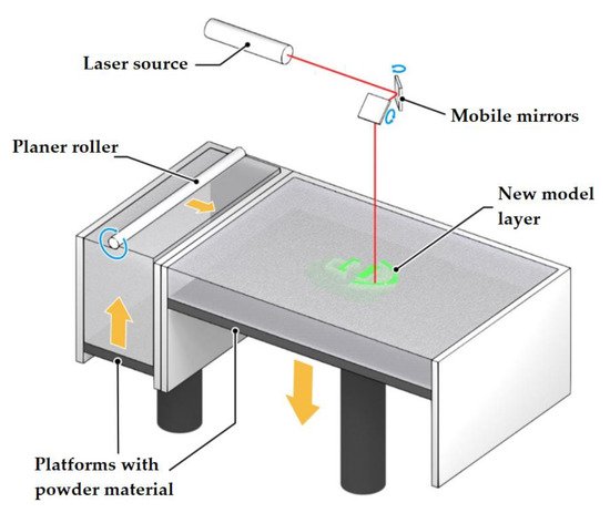 Figure 7. Selective laser sintering (SLS), a schematic diagram.The advantages of the SLS technology are high fabrication precision for products of complex geometric shapes, high speed and performance, excellent mechanical properties of products and the absence of wastes. The disadvantages include the high cost of equipment.The research work [46][51] investigated the possibility of using the SLS technology for handling highly explosive composites such as RDX and TNT. The idea of modifying the method was that explosive particles are covered with a polymer shell with a low melting point. This will ensure easy sintering of particles among themselves while avoiding the initiation of explosives. The SLS concept has been successfully demonstrated on explosive simulators coated with polycaprolactone (PCL). However, the authors still recommend using technologies for the additive manufacturing of explosive materials without the use of intense laser energy (for example, powder printing).