Cone-Beam Breast Computed Tomography: Comparison
Please note this is a comparison between Version 2 by Dean Liu and Version 1 by Avice O'Connell.

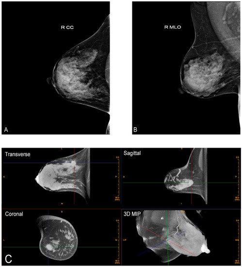
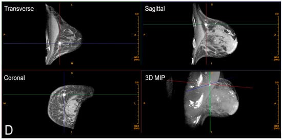
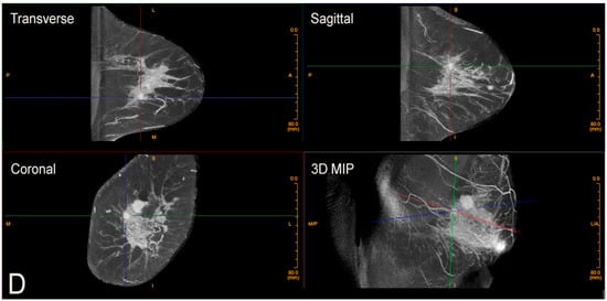
Cone-beam breast computed tomography (CBBCT) is a revolutionary modality that will assist in overcoming the limitations of current imaging for dense breast tissue and overlapping structures. 

  • breast cancer
  • cone-beam breast computed tomography (CBBCT)

1. Introduction

Cone-beam breast computed tomography (CBBCT) was developed with the full knowledge of the many limitations of the current accepted screening modalities available around the world [29,30,31,32,33,34][1][2][3][4][5][6]

2. Advantages of Cone-beam Breast Computed Tomography (CBBCT)

The patient positions herself prone in the machine one breast at a time, inserting her own breast into the opening in the table, thereby placing the breast in the image field. No compression is used which vastly improves comfort.

There is also no intrusive handling of the breasts, which is a completely new consideration of privacy and cultural reservations not previously addressed with current technologies. The technologist checks positioning, making any necessary minor adjustments and then takes one 360-degree image in a period of 10 s. The patient holds still, without a breath hold required. The second breast is imaged in the same way. Efficiency or speed of imaging is another advantage of CBBCT. Standard MRI takes at least 30 min, but with CBBCT, breasts (including the chest wall and axilla) are imaged one side at a time using a single 10 s 360-degree sweep.

CBBCT is not yet approved for screening in the United States at the time of this writing. Its current application is for diagnostic use, which includes all the indications for conventional diagnostic mammography including recall from screening and evaluation of palpable abnormalities. It is also useful for women who cannot tolerate conventional mammography for various reasons. As of May 2020, CBBCT also has its own CPT codes [35][7]. The device also has biopsy capability for findings only seen or best seen by CBBCT. This is analogous to the technique used for prone stereotactic biopsies and MRI biopsies. An additional benefit to CT biopsy is the potential to have excellent evaluation of the surrounding target vasculature. The radiation dose for CBBCT is well within the accepted range for diagnostic imaging and is sometimes less than that of diagnostic mammography [32,36][4][8]. For reference, one study found an average mean glandular dose of 13.9 mGy from CBBCT (range 5.7–27.8 mGy) and an average mean glandular dose of 12.4 mGy from mammography (range 2.6–31.6 mGy) [36][8]. However, this dose range still may preclude its use in routine screening.
Additional advantages of this new technology are many. Because the breast is imaged prone without compression or distortion, there is no overlapping tissue, thereby reducing the likelihood of false positives (a common cause of anxiety provoking recalls for additional imaging (Breast Imaging Reporting and Data System (BI-RADS) 0), which also has benefits for healthcare costs and decreasing unnecessary biopsies. However, perhaps the greatest benefit is CBBCT’s potential increased sensitivity for cancers in dense breasts over mammography, which, as previously discussed, is fundamentally ill-equipped for dense breast evaluation. CBBCT provides a more sensitive evaluation for dense breasts, which is critical as, again, these are the patients at greatest risk for cancer (Figure 1) [33][5]. Better evaluation of dense breast tissue ultimately would equate to earlier cancer detection, less morbidity, and potentially greater cancer survival.
Figure 1. Advantage of CBBCT over mammography for imaging dense breast tissue. Bilateral CC (A) and bilateral MLO (B) views demonstrate dense breasts without focal findings consistent with a negative or BI-RADS 1 mammogram. (C) Post-contrast CBBCT demonstrates a mass denoted by guidelines that is easily recognized consistent with cancer.
This technique also produces true isotropic 3D imaging without a breath hold necessary. Isotropic imaging refers to an imaging process with the same spatial resolution in the X, Y, and Z planes, resulting in a base imaging unit (voxel) equivalent to a perfect cube. The standard imaging unit in the Koning CBBCT machine is 0.273 mm in the X, Y, and Z planes (significantly superior to MRI, which is around 1 mm for a 1.5 T magnet) [24,33][9][5]. A high-resolution mode for calcifications can have spatial resolution of 0.122 mm in the X, Y, and Z planes. Cancer detection requires this excellent spatial resolution, especially for the evaluation of micro-calcifications, which are present in about 55% of non-palpable cancers [37][10]. Most suspicious calcifications are in the range of 100 microns (0.1 mm) [38][11]. While MRI is not always able to add to the diagnostic work-up of microcalcifications, CBBCT does show calcium with adequate resolution (Figure 2) [39][12].
Figure 2. Calcifications on CBBCT. Left CC (A) and MLO (B) views demonstrate pleomorphic micro-calcifications (arrow). (C) Unenhanced CBBCT images showing calcifications, which are marked with grid lines. (D) Contrast-enhanced CBBCT in the same patient showed an incidental mass marked with grid lines.
An additional fundamental advantage of isotropic imaging is that accurate imaging reconstructions in all planes (transverse, sagittal, and coronal) can be reconstructed based off the single acquisition without any image distortion. We like to say you can “manipulate the image, not the patient”. Understandably, women much prefer this. The benefits of isotropic imaging include excellent data acquisition, superior display, and greater compliance from the patient. When combined with compression-free imaging of the breast, the result is true anatomical images of the breast free of anatomical or artifactual distortions. This corresponds to better presurgical planning, ability to perform accurate volumetric analysis for treatment response, quantitative estimates of implant rupture, and overall improved diagnostic accuracy. CBBCT has also shown promise in assisting in the evaluation of different breast cancer types based on imaging morphology [40][13].
Most screening today involves morphological or structural imaging, looking for a mass, asymmetry, or calcification. MRI is the only widely used functional imaging today using IV contrast to show increased flow associated with a mass or malignant structure. The higher sensitivity of MRI is in large part due to the use of contrast, which adds a functional element to the examination. Contrast-enhanced mammography has been described but is not widely used [41,42][14][15]. This was developed in an attempt to gain more information from a mammogram and to make contrast imaging of the breast more available and more affordable than MRI. However, contrast-enhanced mammography still has to contend with compression and distortion and still requires at least two separate views per side.
CBBCT is easily performed after contrast administration (Figure 3). Each breast is imaged in a single 360-degree sweep, before and after contrast administration. Through a peripheral IV using a power injector, non-ionic iodine-based contrast is injected at a rate of 2 cc per second, 1 mg per kg, and the breast is imaged after a short delay (90 s) [29][1]. The other breast may then also be imaged within the next 10 min with excellent enhancement seen. With the use of IV contrast enhancement, the use of CBBCT is expanded to include many of the indications for contrast-enhanced MRI. These include evaluation of extent of disease after a cancer diagnosis, evaluation of response to neoadjuvant chemotherapy, and importantly, imaging women who have a contraindication to MRI such as pacemakers, implanted metallic devices, or claustrophobia. In addition, use of CBBCT circumvents concerns with serial administration of gadolinium and its deposition in the brain [43][16].
Figure 3. Contrast-enhanced CBBCT. Left CC (A) and MLO (B) views demonstrate two masses (black and white arrows). (C) Contrast-enhanced CBBCT with gridlines marking the mass corresponding to the black arrow on mammography. (D) Contrast-enhanced CBBCT with gridlines marking the mass corresponding to the white arrow on mammography.
In conclusion, breast imagers must openly acknowledge the limitations of current technologies, which have been developed to address an urgent need to screen for breast cancer. With constant improvements over the past decades, there has been a demonstrated 40% reduction in breast cancer mortality for those actively screened [44,45,46][17][18][19]. However, we must admit we still fall short and cannot overcome the limitations of painful compression, the need for multiple views, and the inherent enemy of cancer detection, intrinsic breast density. It is time for a paradigm shift. CBBCT provides true 3D imaging in a single sweep without painful compression. This may bring us to a situation where we have fewer false positives and, more importantly, fewer false negatives. This is achieved by using true isotropic 3D imaging for morphological features, combined where indicated with IV contrast for functional imaging, thereby giving us maximum information for earlier cancer detection. Together with improved treatment options, this could lead to better outcomes for all women.

References

  1. O’Connell, A. Cone-Beam Breast CT-Essentials; Imaging Science Today LLC: Vikram Dogra, MD, USA, 2017.
  2. Boone, J.M.; Nelson, T.R.; Lindfors, K.K.; Seibert, J.A. Dedicated Breast CT: Radiation Dose and Image Quality Evaluation. Radiology 2001, 221, 657–667.
  3. Lindfors, K.K.; Boone, J.M.; Newell, M.S.; D’Orsi, C.J. Dedicated Breast Computed Tomography: The Optimal Cross-Sectional Imaging Solution? Radiol. Clin. N. Am. 2010, 48, 1043–1054.
  4. O’Connell, A.; Conover, D.L.; Zhang, Y.; Seifert, P.; Logan-Young, W.; Lin, C.-F.L.; Sahler, L.; Ning, R. Cone-Beam CT for Breast Imaging: Radiation Dose, Breast Coverage, and Image Quality. Am. J. Roentgenol. 2010, 195, 496–509.
  5. O’Connell, A.M.; Karellas, A.; Vedantham, S.; Kawakyu-O’Connor, D.T. Newer Technologies in Breast Cancer Imaging: Dedicated Cone-Beam Breast Computed Tomography. Semin. Ultrasound CT MRI 2018, 39, 106–113.
  6. Prionas, N.D.; Lindfors, K.K.; Ray, S.; Huang, S.-Y.; Beckett, L.; Monsky, W.L.; Boone, J.M. Contrast-enhanced Dedicated Breast CT: Initial Clinical Experience. Radiology 2010, 256, 714–723.
  7. CPT Editorial Summary of Panel Action May 2020: American Medical Association. 2021. Available online: https://www.ama-assn.org/system/files/2020-07/may-2020-summary-panelactions.pdf (accessed on 17 September 2021).
  8. Vedantham, S.; Shi, L.; Karellas, A.; O’Connell, A.M.; Conover, D.L. Personalized estimates of radiation dose from dedicated breast CT in a diagnostic population and comparison with diagnostic mammography. Phys. Med. Biol. 2013, 58, 7921–7936.
  9. Rahbar, H.; Partridge, S.C.; DeMartini, W.B.; Thursten, B.; Lehman, C.D. Clinical and technical considerations for high quality breast MRI at 3 tesla. J. Magn. Reson. Imaging 2013, 37, 778–790.
  10. Ali, M.A.; Czene, K.; Hall, P.; Humphreys, K. Association of Microcalcification Clusters with Short-term Invasive Breast Cancer Risk and Breast Cancer Risk Factors. Sci. Rep. 2019, 9, 14604.
  11. Wilkinson, L.; Thomas, V.; Sharma, N. Microcalcification on mammography: Approaches to interpretation and biopsy. Br. J. Radiol. 2017, 90, 20160594.
  12. Bennani-Baiti, B.; Baltzer, P.A. MR Imaging for Diagnosis of Malignancy in Mammographic Microcalcifications: A Systematic Review and Meta-Analysis. Radiology 2017, 283, 692–701.
  13. Ma, Y.; Liu, A.; O’Connell, A.M.; Zhu, Y.; Li, H.; Han, P.; Yin, L.; Lu, H.; Ye, Z. Contrast-enhanced cone beam breast CT features of breast cancers: Correlation with immunohistochemical receptors and molecular subtypes. Eur. Radiol. 2021, 31, 2580–2589.
  14. Ghaderi, K.F.; Phillips, J.; Perry, H.; Lotfi, P.; Mehta, T.S. Contrast-enhanced Mammography: Current Applications and Future Directions. RadioGraphics 2019, 39, 1907–1920.
  15. Jochelson, M.S.; Lobbes, M.B.I. Contrast-enhanced Mammography: State of the Art. Radiology 2021, 299, 36–48.
  16. Malayeri, A.A.; Brooks, K.; Bryant, L.H.; Evers, R.; Kumar, P.; Reich, D.S.; Bluemke, D. National Institutes of Health Perspective on Reports of Gadolinium Deposition in the Brain. J. Am. Coll. Radiol. 2016, 13, 237–241.
  17. The Swedish Organised Service Screening Evaluation Group. Reduction in Breast Cancer Mortality from Organized Service Screening with Mammography: 1. Further Confirmation with Extended Data. Cancer Epidemiol. Biomark. Prev. 2006, 15, 45–51.
  18. Duffy, S.W.; Tabár, L.; Yen, A.M.; Dean, P.B.; Smith, R.A.; Jonsson, H.; Törnberg, S.; Chen, S.L.; Chiu, S.Y.; Fann, J.C.; et al. Mammography screening reduces rates of advanced and fatal breast cancers: Results in 549,091 women. Cancer 2020, 126, 2971–2979.
  19. Tabár, L.; Vitak, B.; Chen, T.H.-H.; Yen, A.M.-F.; Cohen, A.; Tot, T.; Chiu, S.Y.-H.; Chen, S.L.-S.; Fann, J.C.-Y.; Rosell, J.; et al. Swedish Two-County Trial: Impact of Mammographic Screening on Breast Cancer Mortality during 3 Decades. Radiology 2011, 260, 658–663.
More
Video Production Service