Your browser does not fully support modern features. Please upgrade for a smoother experience.
Please note this is a comparison between Version 1 by Linh Quoc Ve and Version 2 by Jason Zhu.
Ejectors are broadly of two types based on geometric construction, constant area mixing (CAM) and constant pressure mixing (CPM). Eamesproposed a new design with constant rate of momentum change, which has the advantage of both CAM and CPM. Computational and experimental studies show better overall performance of ejectors with increases in critical condensing temperatures and higher entrainment ratios.
- ejector
- design modification
- sustainable design
1. Ejectors
1.1. Construction
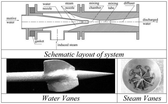
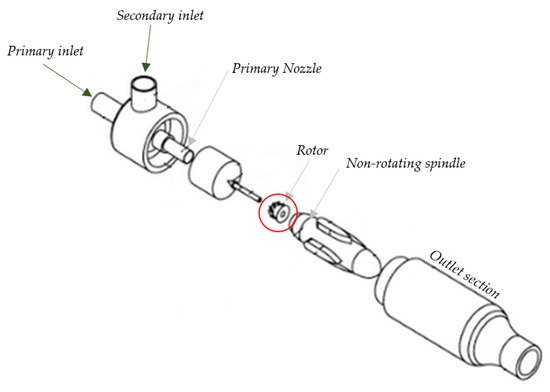
A general ejector is constituted of the inlet pipe, nozzle, suction chamber, mixing chamber, throat and diffuser (Figure 1). Motive and suction fluid of the same or different phases flow through the inlet and suction port, mix in the mixing chamber, accelerate through the nozzle and recover pressure in the diffuser. Primary nozzles are usually of converging/diverging type (based on application). Carbon steel, stainless steel, brass, titanium, PTFE, carbon, poly propylene, UPVC, AB and Hastelloy are common materials used for their construction [1][20].
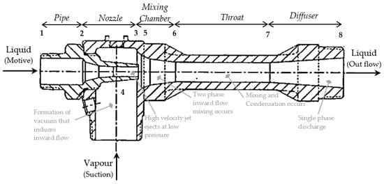
Figure 1. Components in simple ejectors.
1.2. Applications
Operationally, ejectors can be single phase or multiphase systems with compressible or incompressible flow functioning as pump, compressor, heat exchanger, vacuum pump or condenser. Depending on the application, the primary fluid can be liquid, or gas and the secondary fluid can be liquid, gas or particles. Broadly, they are categorized as liquid–liquid, liquid–gas, gas–liquid, gas–gas, liquid–particle and gas–particles ejectors. The application and function of ejectors in several processes has been highlighted below:
1.2.1. Vacuum Pumping and Degassing
The fact of installation flexibility and efficient operation supports ejectors as a suitable alternative for vacuum generation. They are used in vacuum packing, drying, evaporation, gas ejection, etc. processes in industries. [2][21] There is zero secondary flow, while using ejectors as a vacuum pump. Macia et al. explains the influence of zero secondary flow on unsteady phenomenon in vacuum ejectors. [3][22] The physics of vacuum generation and formation of recirculation bubbles on circumference of jets has been visually explained by Kumar et al. [4][23]. In steel industries, larger rejection due to voids and strength led to adaptation of ejector-aided vacuum cooling. After placing of the ladle/mold in the cooling chamber, degassing is performed, which ejects hydrogen, oxygen, nitrogen and other dissolved gases trapped within the mold, ensuring cleanliness, ductility and toughness of the steel. This vacuum is increased at different steps by regulating motive flow [5][6][24,25]. A case study from National Forge Company, PA, recommended vacuum degassing through ejector, as an essential step in producing high quality steel. The installed system was not able to meet the vacuum requirement after being in operation for thirty-six years, pumping hot and dirty gases from steel at a temperature of around 3000 °F. The new system was developed with SS 303 material and ensured periodic cleaning of scales [7][26].
1.2.2. Power Cycle
Although the operational limit of gas turbines is 1200 °C, cost, life and ash deposition limit the maximum steam temperature to 560 °C. The physical structure allows high temperature operation for better efficiency of Rankine cycle but the high steam pressure and resultant dynamic effect on blades limits the range. A topping cycle allows operation of high temperature boilers at low pressures by using very low vapor pressure top fluid, but they require high temperature turbines. [8][27] With an ejector-based topping cycle, they compress secondary gas which prevents loss of exergy through secondary work [9][28]. Oliveira et al. [10][29] developed a combined power generation and cooling cycle in ejector-based Rankine cycles. A part of turbine power output was utilized in running ejector-based cooling systems. The performance of these combined systems was also evaluated by Zhang et al. and Zhang et al. [11][12][30,31].
1.2.3. Other Applications
Desalination: is the major application objective of this work. The prospective application of ejectors in desalination systems for combined vacuum pumping and condensation with active vapor transport has been examined in the later section.
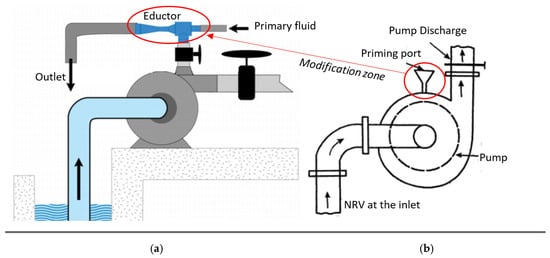
Pump priming: This is essential to minimize start-up damage on the impeller by reducing the gas boundary. Ejectors have been a compulsory part for priming of self-non-priming industrial centrifugal pumps [13][32]. Liquid/compressed air as motive fluid creates a vacuum inside the suction line of the pump, which draws the liquid to submerse the impeller (Figure 2). Vacuum pumps either require liquid supply or limit liquid injection during dry operation, hence ejectors stand out as superior (compared to vacuum pump, priming tank and foot valves). They were found to be installed in any orientation and recorded to be effective in priming up to 8 m suction head with primary fluid pressure of 4–10 bar [14][33]. The flexibility on adjustment of vacuum level and priming speed though primary flow and simple construction and installation makes it more favorable [15][16][17][18][34,35,36,37].
Refrigeration: The requirement of low capital and operational cost, low energy and simplicity has suggested ejector refrigeration systems as a strong alternative to mechanical compressor-based systems [19][20][38,39]. Details on the application in refrigeration technology has been reviewed by several reviewers in the past [21][22][14,17].
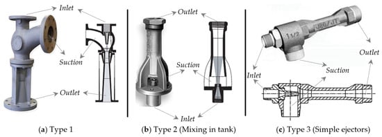
Based on the application in the industrial technologies various ejectors are available in the market. The construction and shapes of ejectors are shown in Figure 3.
1.3. Operational Principle
In the case of ejectors, the jet passing nozzle induces steady flow eddy current to its surroundings, at the suction chamber, due to momentum transfer, which accelerates the secondary flow. During this momentum exchange of primary fluid into secondary, the secondary phase forms dispersed bubbles inside the primary flow stream. This momentum exchange is defined by the momentum exchange coefficient which is a function of drag coefficient, bubble size and phase velocities [30][47]. The potential energy in two phases is converted to kinetic energy through a special case of Bernoulli—Venturi effect, where flow mixes and accelerates through the mixing chamber. The two-phase mixing results in the induction of pressure shock waves of high frequencies. The accelerated flow with dropped static pressure passes through the throat; this causes further movement of the secondary phase from the suction port into the motive stream. At the diffuser section, velocity decreases and hence the fluid recovers pressure energy and compress the secondary phase before discharge. Thus far, the system has been able to recover only about 40% of pressure energy. Here, the system is performing three operations at once, causing suction of low-pressure fluid, mixing it with mainstream and discharging at a higher pressure. The discharge occurs at an intermediate of motive and suction pressure [31][32][48,49].
The static pressure difference in the two-phase flow through a narrow constriction, may result in fan out of primary flow core and form a fictive throat, where flow continues after the secondary flow attains sonic condition. Although not practiced, but concepts on the use of additional suction nozzle for pre-acceleration of stagnant suction fluid has been discussed to reduce large shearing loss during mixing of phases at the high-velocity difference. It can also be a supporting factor to minimize the fan out phenomenon. Performance characteristics of ejectors are defined through suction pressure ratio and mass entrainment ratio. The ratio of system exits to suction flow pressure is suction pressure ratio and the ratio of suction to motive mass flow rate is entrainment ratio. A system is said to be well designed if it has large suction pressure and mass entrainment ratios at the same time [33][50].
1.4. Performance Estimation Parameters
For almost all applications, performance is measured through entrainment ratio (ER) and compression ratio (CR). Compression ratio is the fraction of delivery pressure to suction pressure and entrainment ratio is a fraction of suction mass to motive mass flow rate, numerically defined by equations.˙m
dP
Calculated values of ER for each of the cases of CR are plotted for Figure 4, which forms performance characteristics for the ejector. There are two operational conditions, stable and unstable. With momentum induction of motive flow, secondary flow continuously entrains, resulting in declination of secondary flow pressure, this causes a gradual increment in CR of the ejector. Figure 3 describes three prime operation modes, stable, critical and unstable. At stable, the entrainment ratio remains unchanged until its critical CR is reached. At critical CR, the highest suction occurs, hence it is called maximum discharge point (MDP). Post this, fluctuation and drop in entrainment ratio were observed along with reversed flow. Reversed flow condition is the minimum ER above which motive flow reverses in the loop. Practically, the performance curve is drawn by varying back pressure, at constant inlet pressure and temperature [34][51].
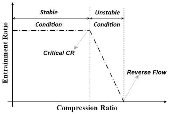
Figure 4. Ejector performance curve.
Experimental methods with implementation of pressure and flow sensors or orifices have been used to log the result for performance estimation. Computational methods with pressures as boundary conditions were found to be abundantly implemented, along with an additional definition of condensation model in some of the cases.
2. Design Modifications of Ejector
Ejectors are broadly of two types based on geometric construction, constant area mixing (CAM) and constant pressure mixing (CPM). Eames [35][52] proposed a new design with constant rate of momentum change, which has the advantage of both CAM and CPM. Computational and experimental studies show better overall performance of ejectors [36][53] with increases in critical condensing temperatures and higher entrainment ratios. Kumar et al. [37][54] considered the rate of energy change as a primary consideration for ejector design. The constant rate of kinetic energy change method allows overcoming the thermodynamic shock by shifting to a description of flow physics.
2.1. Nozzle
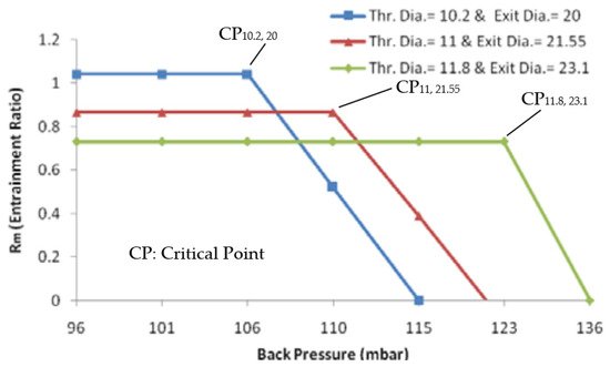
Ariafar et al. [38][55] numerically studied the effect of three different nozzle geometries (throat diameter ranging from 10.2 to 12 mm) on the performance of the thermo compressor, using water vapor as motive fluid with pressure ranging from 1.25 to 1.75 bar. With larger nozzle diameter, higher mass flow rate occurs resulting in higher momentum and kinetic energy hence it results in the formation of high critical back pressure at the system outlet. This in turn has been found to decrease the entrainment ratio (Figure 5).
Behtash et al. [39][56] discussed the effect of different primary flow geometries (two circular nozzles of diameter 15 and 30 mm, two elliptical nozzles with minor and major axis ratios of 0.4 and 0.6 with b = 30 mm, a square nozzle with length 30 mm and two exits) on the interaction of diffracted shock wave patterns and resulting vortex loop emissions.
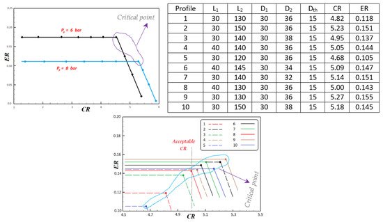
Sharifi et al. [40][57] numerically optimized and verified the performance of a malfunctioning steam jet ejector, for its compression ratio, as the designed primary pressure was 6 bar while its operational requirement of vacuum was achieved when raised to 8 bar. Focusing its application for the MED desalination process for maintaining low pressure inside the evaporator, the study was performed on ten different nozzle geometries for highest entrainment at constant boundary condition. Figure 6 is the result of numerical simulation for the designed pressure of 6 bar and operating pressure of 8 bar. Compared to operating pressure, the designed pressure condition has higher entrainment ratio as the motive mass flow through choked nozzle is higher, while maximum discharge point (MDP) is higher with operating pressure because of larger compression ratio caused by high energy motive steam at high pressure entering the system. Optimization may be affected by several methods but one of the important factors is improving geometries. For technical and financial feasibility, with a goal of attaining desired vacuum level at suction chamber at nominal operating condition of 6 bar, optimization was performed. A nozzle has major dimension parameters, namely, converging and diverging length, inlet, outlet and throat diameters. Higher ER refers to higher suction flow, the 9th profile in the observation shows the highest ER of 0.155 with CR of 5.27.
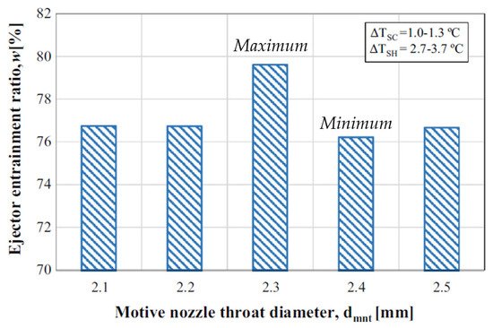
Sag et al. [41][58] experimentally studied the effect of throat diameter and position of primary nozzle on performance of the vapor compression system, with design and manufacturing of ejectors based on established mathematical relations. The system operates on motive fluid such as R134a, causing entrains from the evaporator. Primary nozzles have diameters of 12 mm and angles of 36°, with primary nozzle throat diameters of 2.1, 2.2, 2.4 and 2.5 mm, having constant section throat and mixing chamber of 9 mm. Figure 7 shows entrainment ratios at different motive nozzle throat diameters; at 2.3 mm, the maximum entrainment ratio was observed since the ratio of missing chamber cross-section to cross-sectional area of nozzle throat is optimum. The variation of around 4% with geometry was observed.
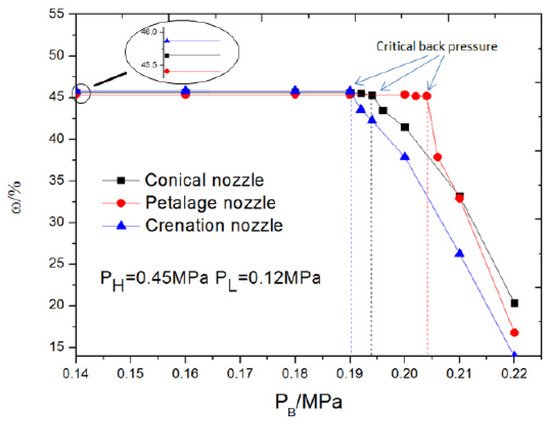
Xue et al. [42][59] used a computational method to study the effect of three nozzles (conical, petalage and crenation nozzles) on performance of supersonic ejectors. Except for outlet shape, all other parameters are kept constant (area ratio, area of throat of mixing chamber to nozzle throat = 3.24, primary throat diameter = 10 mm, length of ejector’s throat is 6 times its diameter; 18 mm, with constant, exiting area). The study focused on critical, sub-critical and back flow operational modes where both back pressure and entrainment ratio were examined to explore the highest back pressure and entrainment ratios. Figure 8 is the plot for entrainment ratio versus back pressure, computed from the numerical study; at initial conditions, entrainment ratio is higher for crenation while at critical back pressure, petalage has highest entrainment as well as back pressure.
Elhub et al. [43][60] studied the optimum position of nozzle exit for cooling cycle in R134a refrigeration systems, through computational method. An extended work is presented with a provision for a movable ejector at varying distance from 2 to 8 mm, to accommodate varying operational requirements and conditions. At low distance, improper mixing between primary and secondary flow resulted in low entrainment, while at higher distance, outlet pressure is found to be more dominant in causing back pressure, hence 3 mm is the optimum distance at which entrainment ratio of about 0.7 was achieved.
Seckin [44][61] used an empirical method to study the effect of constant pressure two-phase ejector primary nozzle throat diameter, on the ejector expansion refrigeration cycle using R134a as the refrigerant. At condenser temperatures of 50, 60 and 70 °C and evaporator temperatures of 0 °C, nozzle throat diameter, condenser temperature and entrainment ratio are affected. With increasing temperature of condenser, larger diameter nozzles are required.
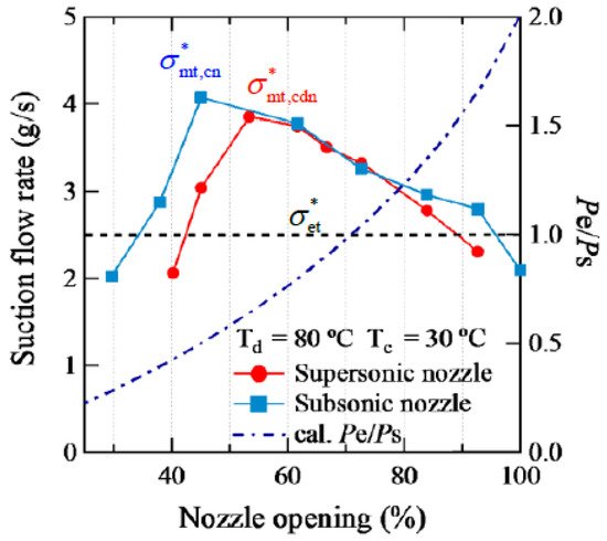
Xu et al. [45][62] performed experimental investigation on supersonic (converging-diverging with throat diameter of 1.3 mm and exist diameter of 1.36 mm) and subsonic (converging with throat diameter of 1.3 mm) nozzle with variable geometry ejector to utilize unstable solar heat as driving energy for stable refrigeration systems. The diameter and length of mixing sections are 2.08 and 10.0 mm, respectively. Driving and suction flow are induced through generator and evaporator, respectively, using R134a as working fluid. Variable geometry ejectors were found to have achieved better performance in varying operating conditions and supersonic nozzles were found to demonstrate better performance compared to subsonic nozzles. Figure 9 shows the performance of ejectors for varying nozzle openings for two different nozzle geometries, where optimum point for best performance was observed, which decreases on both sides.
2.2. Primary Nozzle Position
Conventional ejectors are designed to operate at a single optimum point; in practice operation may vary from it, which results in performance deterioration. Nozzle optimum position is to be set such that no secondary flow occurs.
In the mixing section, motive and suction fluid mixes in the phenomena of heat and mass transfer, during pressure recovery of this flow shock waves are induced in the diffuser. Zhang et al. [46][63] computationally studied the effect of varying primary nozzle openings on ejector operation. Pressure of 300 kPa, 80 kPa and 220 kPa were selected for motive inlet, suction and outlet, with water vapor as motive fluid. Results based on turbulence models k-e standard, k-e RNG and k-e RSM, were compared with experiments and were compared with experimental conditions. Performance deterioration with exceeding discharge pressure beyond critical pressure was observed, where computational results with k-e RSM, were in better agreement with experiments. A difference in entrainment ratio of 0.1 was observed, which is around a 47% improvement.
Dong et al. [47][65] used movable primary nozzles of three kinds and diffusers of two kinds for identifying its optimum position and design, respectively, experimentally in the refrigeration cycle (described in Figure 10). Variation in optimum operational position was observed in all the cases with better coefficient of performance for nozzle 1, location of position optimum position is dependent on the kind of nozzle being used and it is independent of the type of diffuser being used.
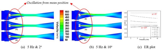
Mani et al. [48][66] used UDF function to define oscillation between two points, for computational analysis of oscillating primary nozzle. Figure 11a,b is the velocity contour plot for oscillation at 5 Hz frequency at 2° and 10° angles, with inlet, suction and outlet pressure boundary conditions as 4.5 bar, 1 bar and 1 bar respectively. It shows that velocity waves transport along with the axial plane of the system. Figure 11c is the plot for varying frequency at different oscillation angles. In observed cases, ER is lower compared to the steady result, but comparing absolute oscillating ranges, it shows improvement in results with increasing oscillation angle; R&D can focus on discovering a suitable combination of amplitude and frequency to enhances performance. There are challenges in integration of actuator for consistency in oscillation in the technology.
2.3. Inlet Swirling Vanes
Performance of the ejector system can be enhanced by proper mixing of motive and suction flow. Improvement in entrainment ratio by inducing swirl in primary flow has been studied [49][67], it has been highlighted to have increased contact time between primary and secondary flow with increased shear force effect.
Yan et al. [50][68] studied the effect of swirling vanes (for both steam and water) on injectors with central water jets (Figure 12). Two swirling water vanes were present at the beginning of nozzle throat while eight steam swirling vanes were present, which caused disturbance in the velocity field inducing vortexes when flow passes through it. Observations for entrainment ratio and resistance coefficient were performed for an inlet pressure of steam and water and temperature. Water swirling vanes were found to be efficient in improving entrainment ratios, exergy and resistance coefficients, while steam swirling vanes caused degradation in performance.
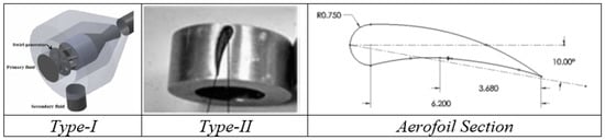
Banu et al. [51][69] focused on an air ejector system to analyze the influence of swirl for prospective application in vapor jet refrigeration. A three-dimensional numerical approach basis, with and without swirl, has been studied and verified through PIV technique. Figure 13 depicts the aerofoil cross-sectioned swirl generators, type-I and type-II, implemented in the system, placed at convergent section upstream. For geometry with primary nozzle diameter and area ratio of 3.2 mm and 2.56, an air compressor system with 100 L reserve was used in a transparent system. Primary flow measurement was performed through rotameter while secondary is measured with an orifice meter. With an increase in radial velocity compared to no swirl, there has been an enhancement of performance by 5% [52][70], 2% and <2% for cases with type-I, type-II with 5 vanes and type-II with 3 vanes.
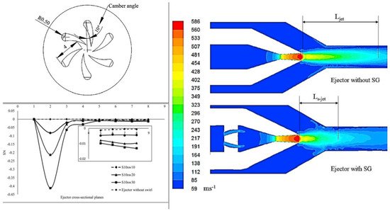
Banu et al. [53][71], performed 3D numerical simulations for a different arrangements of type-I swirl generators with sweep angles of 10°, 20° and 30°, discussed in [20][39] along with verification through PIV. The swirling intensity was quantified with the non-dimensional parameter swirl number (SN); a ratio of the axial flux of tangential momentum to axial momentum as defined by the following equation [54][72].x Uθ r dAR∫R0ρ Ux2 dA
Figure 16 shows a reduction in axial velocity with primary stream pressure due to decreasing static pressure at the throat, causing velocity decay exponentially along the ejector. A sweep of 30° in cavity type swirl generator showed 15% improvement in ER.
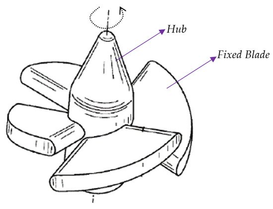
Chlappetta et al. [55][73] created a US patent for swirl vanes in vapor compression refrigeration systems shown in Figure 15. In addition to stationary swirling vanes, free spinning rotors were actively used in exchanging pressure and enhancing mixing. Garris et al. [56][74] mounted a free-spinning rotor on a fixed spindle (Figure 16). It uses non-steady fluid and supersonic flow principles to obtain compression of induced flow. This reduces losses during turbulent mixing, allowing better adiabatic efficiency during the topping cycle of rankine and gas cycles and refrigeration cycles. Hong et al. [57][75] updated the research status of this novel design computationally, with various geometrical arrangements; the geometry of rotor vanes was prioritized with leading and trailing edge and cross-sectional shape [58][76].
2.4. Throat Sizes
Water is an excellent refrigerant with high latent heat of vaporization, specific heat, suitable heat transfer characteristics, non-corrosive and adoptable by environmental concerns. In refrigeration systems, ejector performance is the deciding factor governing overall coefficient of performance. Ejector efficiency is governed by the entropy generation process, where conventional systems have two major sources: turbulent mixing and strong normal shock waves.
Alhussan et al. [59][77] varied the throat diameter ratio to investigate the structure of flow induction in an unsteady supersonic fluid with steam as the motive fluid. The pressure exchange ejector showed the mass flow ratio to be near to unit with high-pressure recovery.
In a vapor compression refrigeration cycle, throttling is a significant loss, hence modification through adaption of ejectors ensure optimized performance. Chaiwongsa et al. [60][78] studied the effect of throat diameter of the motive nozzle (0.8 mm, 0.9 mm and 1 mm) on CoP of a refrigeration systems with R134a for primary and secondary flow. A system with smaller diameter is found to have larger COP.
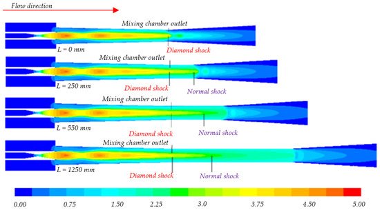
Bi et al. [61][79] developed a computational model to study the effect of throat diameter. Their results showed no significant change in the entrainment ratio location of diamond shock (abrupt standing shock wave variation) (Figure 17). Increasing length increased friction resistance, which eventually increased the critical back pressure up to its maximum value of operation and then decreases. For operational conditions, there is always an optimum point, and in this case, it was 550 mm.
Saini et al. [62][80] experimentally studied vacuum pressure for three throat lengths (10 cm, 20 cm and 30 cm) with constant throat diameter of 2 cm. Suction capacity was examined based on the absorbed weight of saw dust from the suction port. At 30 cm, a minimum pressure of 87.5 kPa and maximum suction of saw dust 32.2 grams were measured, as compressive strength at the top of the ejector will be converted to flow velocity with longer length.
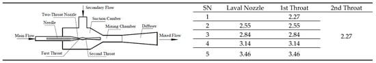
Ren et al. [63][81] used a two-throat nozzle ejector in a TPERC (two-phase ejector refrigeration cycle) system and experimentally observed the consequent entrainment ratio using R134a refrigerant. Figure 18 provides the geometric description for de Laval and two throat nozzles, in both cases entrainment ratio was increased with cross-sectional area, but the value was larger (i.e., 0.375) for the two-throat system.