1. Introduction
It is widely believed that the most efficient strategy to achieve meaningful reduction in greenhouse gas (GHG) emissions is by electrification of transportation and expanding the use of renewable energy sources. Both of these approaches require transformative energy storage technology
[1][2][3][4][5][6][1,2,3,4,5,6]. One of the most promising energy storage technologies is solid-state lithium batteries (LBs)
[7][8][9][10][7,8,9,10]. LBs are rechargeable, and they were first introduced on the market by Sony Corporation in 1991
[11]. One of the key distinctions of LBs is that they have a much higher energy density than conventional nickel-cadmium (Ni-Cd)
[12], lead-acid (Pb-acid)
[12], nickel-hydrogen (Ni-H
2)
[13], and silver-zinc (Ag-Zn)
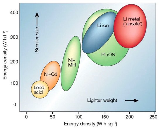
[14] batteries represented in a Ragone plot (
Figure 1).
Figure 1. Ragone plot of lithium batteries
[15].
However, another safety issue common for conventional LBs is the high flammability and low thermal stability of organic liquid-state electrolytes
[16][17][18][19][16,17,18,19]. This issue can be solved by substituting solid-state electrolytes (SSEs) in place of liquid-state electrolytes
[20][21][22][20,21,22]. Solid oxide electrodes and electrolytes enable energy/power cells to operate at a higher temperature range and accelerate reactions at the cathode and anode, leading to a higher discharging/charging rate. In addition, SSEs have wider electrochemical windows that increase their adaptiveness to high-voltage cathode materials and lithium-metal anodes, which can also enhance the energy density (up to 70%
[23]) and cycling performance of LBs. When combined with a lithium metal anode and Ni-rich oxide ceramic cathode, SSEs can enable the safest batteries with the highest energy density to meet the demand for electrification of air and surface transportation
[24].
SSEs include polymer, inorganic (e.g., ceramic-based oxide electrolytes) and hybrid electrolytes. Free-standing polymer electrolytes could be prepared with proper crosslinkers
[25][26][27][28][29][25,26,27,28,29] followed by photopolymerization as an in-situ approach
[30][31][32][33][34][30,31,32,33,34]. Fabricated gel polymer electrolytes are capable of creating high-quality interfacial contact with electrodes and good electrochemical properties
[35]. Besides, Li et al.
[36] and Yao et al.
[37] presented recently progress on polymer-based electrolytes. Unfortunately, they still have limited ionic conductivity at room temperature. Inorganic oxides SSEs mainly include perovskites, garnets, NASICON-type, and LISCON-type
[38]. Cao et al.
[38] comprehensively reviewed inorganic SSEs for lithium batteries. Similar to perovskites, hybrid polymer-ceramic systems utilize ceramic fillers with garnets as a dispersant into the polymer matrix (i.e., poly (ethylene oxide) (PEO)-based, polyacrylonitrile(PAN)-based, polyvinylidene fluoride (PVDF)-based, etc.)
[39]. Goodenough et al.
[40] fabricated low-cost hybrid PEO-LLZTO electrolytes and applied them in LiFePO
4|Li cells that delivered high discharge capacity (139.1 mAh g
−1 with capacity retention of 93.6% after 100 cycles). Falco et al., innovatively prepared cross-linked hybrid electrolytes to enhance ionic conductivity by mixing LLZO, lithium bis(trifluoromethanesulfonyl) imide (LiTFSI), tetra (ethylene glycol dimethyl ether) (G4) together under UV-light
[41][42][41,42]. The hybrid electrolytes exhibited excellent ionic conductivity of 0.1 mS cm
−1 at 20 °C. Passerini’s group
[43] presented UV cross-linked PEO polymer electrolytes
[44] with ionic liquids. The room temperature ionic conductivity could reach nearly 10
−3 S cm
−1.
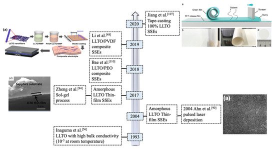
We summarized the progress of LLTO electrolytes in solid-state LBs (as shown in Figure 2). Many investigations have been undertaken on LLTO composite SSEs and electrochemical performance of selected electrolytes are summarized in the Table 1. However, hybrid electrolytes still suffer safety issues due to the flammability of the organic polymers. There is few research working on 100% ceramic electrolytes in solid-state LBs applications.
Figure 2. Timeline for the development of typical LLTO (La2/3−xLi3xTiO3) solid-state electrolytes (SSEs) in lithium metal batteries.
Table 1. Summary of electrochemical performance for selected LLTO SSEs in LBs.
| SSEs Composition |
Anode|Cathode |
Ionic Conductivity (S cm | −1 | ) |
Discharge Capacity/Charging rate/Cycle Number (Capacity Retention Rate) |
| LLTO/ | 1 | PAN/ | 2 | SN [45] |
|
|
151 mAh g | −1 |
| Li|LiFePO | 4 |
2.20 × 10 | −3 | at 30 °C |
C/2 |
| |
|
150 (data unavailable) |
| LLTO/ | 3 | PEO/LiTFSI/SN [46] |
Li|NMC 532 |
>10 | −3 | at 55 °C |
143.2 mAh g | −1 |
C/20
30 (data unavailable) |
| LLTO/PEO [47] |
|
|
147 mAh g | −1 |
| Li|LiFePO | 4 |
3.31 × 10 | −4 | at | 7 | RT |
C/10 |
| |
|
100 (~98%) |
| 15 wt.% LLTO/ | 4 | PVDF [48] |
Li|LiFePO | 4 |
5.3 × 10 | −4 | at 25 °C |
121 mAh g | −1 |
1C
100 (~99%) |
| LLTO/PEO/LiTFSI [49] |
Li|LiFePO | 4 |
1.3 × 10 | −4 | at 60 °C |
144.6 mAh g | −1 |
1C
100 (~96%) |
| LLTO/PEO/LiTFSI [50] |
Li|LiFePO | 4 |
1.6 × 10 | −4 | at 60 °C |
135 mAh g | −1 |
2C
300 (79%) |
| 5 wt.% LLTO/PEO/LiTFSI [51] |
Li|LiFePO | 4 |
3.63 × 10 | −4 | at 60 °C |
123 mAh g | −1 |
C/2
100 (94%) |
| 8 wt.% LLTO/PEO/ | 5 | PPC/LiTFSI [52] |
|
|
135 mAh g | −1 |
| Li|LiFePO | 4 |
4.72 × 10 | −4 | at 60 °C |
C/2 |
| |
|
100 (96%) |
| 3wt.% LLTO/PEO/LiClO | 4 | [53] |
Li|LiFePO | 4 |
4.01 × 10 | −4 | at 60 °C |
[58]) that provide potential applications even at extreme conditions.
However, there are several challenges that hamper the application of LLTO SSEs in batteries. First of all, the large grain boundary resistance reduces total ionic conductivity below 10
−5 S cm
−1 at room temperature
[58]. Secondly, LLTO is chemically unstable when in direct contact with lithium metal. Lithium can be intercalated into LLTO at voltages below about 1.8 V, which causes the Ti
4+ reduction and enhanced electronic conductivity
[58]. Thirdly, the brittleness nature of LLTO makes it hard to fabricate and assemble into batteries. Besides, due to internal volume changes of batteries during operation, delamination of the ceramic oxide electrode and electrolyte layers can occur, causing the battery life to be shortened
[59].
In this review, we presented and analyzed the origins of large grain boundary resistance for LLTO and solutions. We also gained an insight to the chemical instability of LLTO electrolytes when contacts lithium-metal anode. Moreover, we reviewed the tape-casting fabrication methods and electrochemical performances for 100% amorphous and crystalline LLTO SSEs in LBs.
2. Crystal Structure/Composition of LLTO and Relationship to Ionic Conductivity
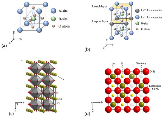
Perovskite La
2/3−xLi
3xTiO
3 (LLTO)-family (0.04 < x < 0.16) with ABO
3 structure (
Figure 4a,b) has Li, La (La-rich and La-poor regions), and vacancies occupying the A sites, and Ti-ions occupying B sites that are octahedrally coordinated by oxygen
[60].
Figure 4. (
a) ABO
3 structure; (
b) La-rich and La-poor regions; (
c) Crystal structure of (
P4/mmm)-type LLTO
[60]; and (
d) bottleneck structure of 12-fold coordinated with oxygen ions
[60].
Figure 4c indicates the crystal structure of the tetragonal-type perovskite with the lattice parameter of a = 3.8 Å
[60] for cubic unit cell. Various x values of the lithium and lanthanum lead to distorted structures which generally originates from the unequal distribution of vacancies and displaced cations of Li
+ and La
3+. The bottleneck structure of perovskites consists of 12-fold coordinated with corner-shared oxygen as shown in
Figure 4d
[60]. The stable structure could be maintained when the x value is between 0.04 and 0.16.
Cubic and tetragonal LLTO (x ≈ 0.11) display a lattice structure with the stacking of La-rich and La-poor regions (
Figure 4b) to maintain high bulk conductivity
[60]. Inaguma and Itoh
[61] showed that the conductivity of LLTO solid solution shows a parabolic dependence on x due to variations in the lithium to vacancy concentration and the formation of low activation energy pathways for ions controlled by site percolation and bottleneck size.
A lot of research has been dedicated to perovskite-type electrolytes to better understand the relationship of the chemical composition, crystal structure, and synthetic methods on lithium ionic conductivity
[60][61][60,61]. Many works synthesized LLTO that the content of lithium around 0.11. Proper adjustments of this value depend on dopants in LLTO.
Table 2 shows the summary of room-temperature ionic conductivities for selected LLTO SSEs (with common dopants) ionic conductivity at room temperature. The optimal x with the highest conductivity (more than 10
−4 S cm
−1 at room temperature) was found by many researchers to be around ~0.1 (LLTO commercial powder from TOHO TITANIUM Co., Ltd.).
Table 2. Summary of selected LLTO SSEs in ionic conductivities.
| Composition |
Space Group |
Conductivity at RT (S cm | −1 | ) |
Synthesis Method |
| Type I: pure LLTO SSEs |
|
| La | 0.61 | Li | 0.17 | TiO | 3 |
Cmmm |
3.76 × 10 | −4 |
Pulsed Laser Deposition [62] |
| La | 0.5 | Li | 0.5 | TiO | 3 |
P4/mmm |
3.52 × 10 | −7 |
Spin Coating [63] |
| |
P4/mmm |
7.2 × 10 | −7 |
Microwave Sintering Method [64] |
| Type II: composite LLTO SSEs |
|
| La | 0.5 | Li | 0.5 | TiO | 3 | /nano-Ag |
Pm3m |
2.8 × 10 | −5 |
Sol-gel Processing [65] |
| La | 0.5 | Li | 0.5 | TiO | 3 | /silica |
P4/mmm |
1 × 10 | −4 |
Wet Chemical Method [66] |
| Sr-doped La | 0.56 | Li | 0.33 | TiO | 3 |
Pm3m |
9.51 × 10 | −4 |
Sol-gel Processing [67] |
| Y-doped La | 0.46 | Li | 0.33 | TiO | 3 |
P4/mmm |
1.95 × 10 | −3 |
Sol-gel Processing [68] |
| Nb-doped La | 0.5 | Li | 0.5 | TiO | 3 |
P4/mmm |
1.04 × 10 | −4 |
Solid-state Reaction Method [69] |
| Sr/Co-doped La0.557Li0.33TiO3 |
Pmm
|
1.4 × 10 | −4 |
Solid-state Reaction Method [55] |
| 140 mAh g |
| −1 |
| 1C |
| 100 (92.4%) |
| LLTO/ | 6 | BC [54] |
|
|
151.7 mAh g | −1 |
| Li|LiFePO | 4 |
1.54 × 10 | −3 | at RT |
C/5 |
| |
|
100 (98.5%) |
| Sr/Ta co-doped LLTO [55] |
Li|LiFePO | 4 |
1.40 × 10 | −4 | at 25 °C |
83.8 mAh g | −1 |
C/10
80 (89%) |
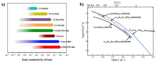
Perovskites usually demonstrate relatively high lithium-ion conductivities (10
−3~10
−4 S cm
−1 at room temperature as shown in
Figure 3a and low electronic conductivity
[56] (i.e., 10
−8 S cm
−1). Inaguam et al.
[57] was the first to report LLTO solid-state electrolytes (SSEs) with relatively high bulk ionic conductivity (i.e., 1 × 10
−3 S cm
−1 at room temperature) and total ionic conductivity (i.e., >2 × 10
−5 S cm
−1 at room temperature).
Figure 3b shows the Arrhenius plots of the ionic conductivities of the perovskite compared with other ceramic SSEs. Thus, LLTO has been widely used as an additive within polymers to form composited electrolytes for ionic conductivities enhancement.
Figure 3. (
a) Typical SSEs with highly ionic conductivities at room temperature; and (
b) ionic conductivities of selected SSEs with elevated temperature. Reprinted (adapted) with permission from
[56]. Copyright 2017 American Chemical Society.
In general, LLTO has many advantages: (1) large ionic transference numbers (i.e., 0.5~0.9); (2) superior chemical and thermal stability in air; and (3) environmental friendless without any release of toxic gases during decomposition reactions. Besides, LLTO SSEs show wide electrochemical windows (8 V vs. Li/Li+) that increase their adaptiveness to high-voltage cathode materials and if combined with lithium-metal anodes. Also, LLTO exhibits excellent thermal stability (4–1600 K