Electrofiltration is emerging as an attractive alternative that uses electric field to assist in fouling mitigation during the membrane-based separation processes. By tuning the electrophoretic forces on the feed side of the membrane, all water constituents (except ions) including viruses, bacteria, small and large molecules, and organic and inorganic solids can be prevented from fouling the membrane surface. Theoretically, the electric field-assisted membrane separation process will result in greatly desired clean water flux for the entire duration of operation.
- membrane separation processes
- electrofiltration
- antifouling
- physical cleaning methods
- energy costs analysis
1. Introduction
Membrane separation processes exploit a universal physical property of matter-size. Membranes are thin semipermeable layers that could filter through liquids but retain ions, molecules, and/or particles that are larger than the pore size [1]. By choosing proper operational conditions and membrane materials, the membranes could theoretically separate ions, molecules, and colloids from liquids, with sizes ranging from sub-nanometer scale to several micrometers [2]. This size selection mechanism allows membrane processes to be an attractive alternative to conventional water and wastewater treatment methods.
All membrane processes suffer from two major limitations, namely, fouling and concentration polarization that hinder wide-scale implementation of membrane technologies [3]. Fouling occurs when ions, molecules, and/or particles ( aka foulants) deposit and accumulate on the membrane surface, which ultimately builds up to a cake or gel layer that increases the required operational pressure for membrane filtration. Fouling is also a consequence of the high local concentration of foulants in the boundary layer at the membrane surface [4][5][4,5]. Concentration polarization occurs when the foulants concentrate and create an elevated concentration gradient near the membrane surface, which eventually leads to multiple effects in membrane filtration including an exacerbated fouling issue, back diffusion towards bulk solution, and an increased osmotic pressure gradient to overcome [3][6][3,6]. Concentration polarization frequently occurs in high pressure-driven membrane processes, including nanofiltration and reverse osmosis [7][8][7,8]. Thus, the extent of fouling and/or concentration polarization is determined by complex interactions, between the foulants and the membrane material, that are governed by water chemistry, membrane types and properties, and hydrodynamic conditions.
To address the above limitations, membrane processes commonly employ physical and chemical strategies to remove the foulant layers and/or reduce concentration polarization in membrane systems [9]. In physical cleaning, fluid shear forces are used to clean membrane surface in order to remove reversible foulants [10][11][10,11]. For instance, the transmembrane pressure is reversed to flush off foulants blocking the membrane pores. Alternatively, high crossflow velocities are used to scour the cake or gel layer off the membrane surface. In membrane plants, backwashing takes about 1/30 to 1/10 of operation time and at a flux about 1:1 to 3:1 to the operational flux [9]. In chemical cleaning, commercial products (e.g., acids, bases, and surfactants) are used to remove irreversible foulants and recover membrane performance [9][12][9,12]. Acids, such as oxalic, citric, nitric, hydrochloric, phosphoric, and/or sulfuric acids, are used to remove inorganic foulants, whereas oxidants and disinfectants are used to remove organic foulants and biofoulants [9]. Despite the application of both physical and chemical cleaning strategies, membrane performance would still decline over time and eventually new membrane modules must be installed to replace the fouled ones [13]. Another costly shortcoming for both traditional cleaning strategies is that they both require the filtration process to be partially halted to perform the cleaning task, which reduces the overall productivity of the process. In addition, use of clean water and chemicals also directly adds to the overall costs of membrane operation and environmental impacts.
Electrofiltration, an electric field-assisted membrane process, is emerging as an attractive alternative that uses electric fields to assist in fouling mitigation during the membrane filtration [14][15][16][21,22,23]. The term ‘electrofiltration’ was exclusively used in discussion of electrophoresis and electroosmosis in earlier literature [17][18][24,25]. However, more recent publications expanded the usage of electrofiltration to include electrochemical reactions [14][19][21,26]. In electrofiltration, an electric field is applied across the membrane where the field is usually perpendicular to the membrane surface [20][21][27,28]. This technique can introduce in situ electrokinetic and electrochemical effects, such as electrophoresis, electroosmosis, electrolysis, electrocoagulation, and dielectrophoresis on demand [14][22][21,29]. These techniques would alter both the transport and deposition of the foulants that influence the structure of the cake or gel formation on the membrane surface. When compared to the conventional membrane processes (no electric field), the electric field-based effects would not only improve membrane performance, but also reduce the additional chemical use to control fouling. Electrofiltration is a very promising technique for the following reasons: (1) as a non-chemical method, it does not introduce additional contaminants into the permeate stream or the retentate stream, (2) application of the electric field does not interfere with continuous membrane operation, and (3) the electric field parameters (electric field strength and frequency, continuous vs. pulsed field) can be varied depending on the feed water composition, in order to mitigate membrane fouling.
2. Mechanisms of Electrofiltration
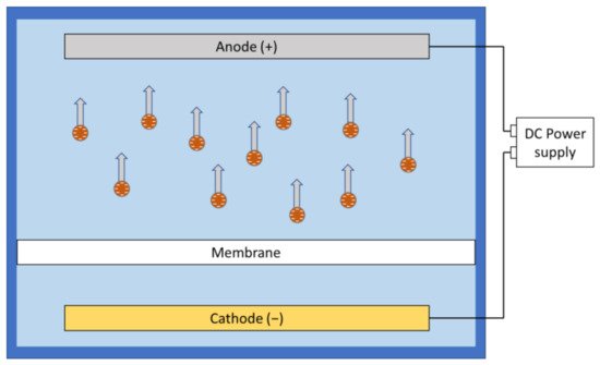
Under electrophoresis, charged particles or ions will be accelerated along the electric field and potentially moved away from the membrane. In aqueous environment, particles tend to be negatively charged as the positive ions are smaller and more likely to be hydrated compared to the larger negative ions that are more likely to be adsorbed [23][65]. Furthermore, pH adjustment could affect the zeta potential and modify the surface charge on the foulants [21][28]. This enables the researchers to use simple direct current (DC) field setups to move most of the negatively charged foulants away from the membrane surface by placing the anode on the feed side of the filtration system ( Figure 12 ). However, electrophoresis is less effective in dealing with foulants with high mass-to-charge ratio.
Electroosmosis is the movement of a liquid relative to charged particles or membrane surface in the presence of an applied electric field [24][66]. ( Figure 23 ).
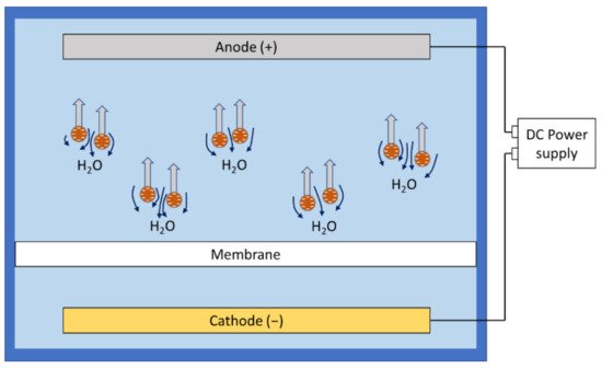
With a clever design of experimental setups, some researchers could observe and identify electroosmosis as the most significant effect in fouling reduction. Chuang et al. used the relative size of the membrane pore and different foulant components to create a scenario where the presence of electroosmosis could be confirmed by suddenly shutting off the electric field [21][28]. A sudden decrease in permeate flux was observed, but the flux loss was immediately recovered with the electric field reinstalled. The application of electroosmosis in electrofiltration is highly conditional, depending on the foulant composition and membrane structure, and it may not be ready for any large-scale real-world feed water compositions.
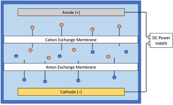
Another limitedly popular concept in the literature of electrofiltration is electrodialysis. However, electrodialysis is an exploitation of electric field to aid the movement of ions in ion exchange process, involving ion-exchange membranes ( Figure 37 ). The concept has been brought up in studies where ion exchange was coupled with ultrafiltration or reverse osmosis, but this mechanism does not directly affect the fouling behavior of membrane processes [25][26][82,83].
3. Characterization of Electrofiltration
The universal measurement of the performance of electrofiltration in the reported studies is the permeate flux, as it is measured by engineers in practice as an indicator of membrane performance. Permeate flux intuitively and quantitatively demonstrates the performance enhancement under different setups of electric field compared to the control groups without the field. The real-time flux measurements are obtained by recording the total weight of collected permeate at different time stages, usually collected automatically by an online system. The information obtained from flux monitoring allows researchers to develop and test various models for electrofiltration. While most researchers would only report the flux decline under continuous flow of feed water with foulants, others introduced ultrapure water again at the end of the filtration to estimate the resistance due to only the cake layer by normalizing the final resistance with the initial resistance [27][28][36,53].
A widely used method to qualitatively evaluate the performance of electrofiltration is visual observation of the fouling conditions on the membrane. Direct optical observation is facilitated by using transparent materials in the filtration module customization, e.g., plexiglass [29][35]. In addition to optical observation, scanning electron microscopy, confocal laser scanning microscopy, and other light microscopy have been applied to study and compare the membrane surface before and after fouling in ex situ analysis [30][31][32][31,39,44].
For researchers who fabricated membranes with specific properties, for example, electrocatalysis and conductivity, additional techniques are used to characterize the membranes. X-ray photoelectron spectroscopy is used to study the chemical functional groups on the membrane. Transmission electron microscopy is used to study the morphology of the membrane. Impedance spectroscopy is used to study the conductivity of the membrane [33][34][32,55].
Real-time monitoring of membrane fouling using quantitative tools has been gaining attention in the membrane applications [35][84]. In the context of electrofiltration, the application of real-time monitoring tools could provide direct information on the effects of electric field on membrane fouling. In situ visualization of fouling by magnetic resonance imaging has been reported in the more general literature for membrane filtration, however, it is yet to be applied to study electrofiltration [36][37][85,86]. Similar efforts have been reported with infrared or UV-vis spectrophotometry techniques [38][39][40][41][87,88,89,90]. Other methods with growing popularity include acoustic-based techniques [42][43][44][45][91,92,93,94]. Currently, incorporating the fouling monitoring device into the membrane system is a challenge and it may potentially interfere with the electrofiltration process. To address this challenge, a new filtration module must be designed to allow simultaneous application of the electric field and the real-time monitoring of fouling. For example, magnetic resonance imaging or ultrasound could potentially be more plausible in electrofiltration studies for real-time monitoring, but their cost and large-scale feasibility is a concern due to a combined effect of the specific requirements of membrane modules, monitoring techniques, and the data processing technologies [46][95].
4. Quantification and Modeling Efforts of Electrofiltration
Modeling remains a crucial aspect to unify and compare the results from various electrofiltration studies, a need that was demonstrated in the last section. More efforts are needed to provide a quantitative tool to relate the aforementioned factors to electrofiltration results, which, in turn, provides further insights on mechanistic understanding of the process. Thus far, the progress in this area is relatively preliminary compared to the experimental studies.
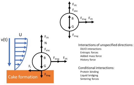
Some researchers developed simplified free body diagrams of the interactions on a single particle to illustrate the interactions in electrofiltration [21][47][48][28,52,124]. These models could be effective in providing a mechanistic understanding of the foulant behavior in electrofiltration. Agana et al. ’s study provided a model to describe various forces acting on a particle in the electric field. The forces acting on the foulant particle included the drag force, the lift force, the gravitational force, the buoyancy (pressure gradient) force, the van der Waals force, the electrostatic double-layer interactions, and the electrophoretic force [47][52]. This model assumed that electrophoresis is the dominant effect a priori and omitted other aforementioned mechanisms in electrofiltration. In some studies, the researchers have reported theoretical calculation of particle trajectory for rather specific scenarios that described their experimental setup. Molla et al. and Du et al. separately provided a trajectory calculation for particles under their dielectrophoretic setup [49][50][42,79]. For more general cases, such electrodynamic models are usually limited due to the omission of many crucial interactions, such as particle collision, forces due to unsteady flows, and Brownian motion for particulate flow in the studies of membrane filtration ( Figure 411 ) [51][125]. An order of magnitude analysis may suggest some of these interactions might not be significant under certain experimental setups or real-world applications; however, such analysis has not been found in the literature in studies on electrofiltration.
In the late 20th century, the principles of fluid dynamics were applied to characterize membrane processes [52][53][54][126,127,128]. Recently, conventional membrane filtration studies without field assistance have also used computational fluid dynamics (CFD) to understand fouling behavior and flux recovery [55][56][129,130]. However, thus far, the development of CFD for electrofiltration is lacking, but it may gain momentum when electrofiltration is more widely used.
With the advancement in computational science and simulation methods, analysis of complex process such as membrane fouling are now possible. For instance, a Monte Carlo simulation of the foulant structure has been demonstrated by Chen et al. for a simplified scenario where only mass transport, drag force, electrostatic force and van der Waal’s force were considered [57][131]. Based on input parameters—including Hamaker constant, surface charge, dielectric permittivity of water, permittivity of free space, temperature, and membrane resistance-steady states of foulant layer were estimated by calculating energy change in each simulation step, and the final results were visualized in terms of volume fraction. A follow-up paper by them also highlighted the limitations and knowledge gaps of their method [48][124]. As a deterministic model, a thorough representation of all interactions in membrane filtration is necessary for this simulation method to be accurate and useful. Efforts have been made to improve this method in latter studies by introducing fluid dynamic consideration with an updating velocity profile [58][132]. If researchers are interested to extend this method to study electrofiltration, more studies on the quantification of fundamental mechanisms in electrofiltration will be necessary.