The large increment expected in the diffusion of light-electric vehicles will raise several issues that must be addressed to cope with this trend, including battery diagnostic and maintenance services. The battery system is the most expensive part of the majority of e-mobility devices. Therefore, battery manufacturers tend to reduce the battery cost by using simple battery management systems that provide only basic safety features. Possible advanced functionalities are not implemented and the battery may lose performance during its use. Widely spread maintenance centers are thus required to support the mobility electrification process, but their diffusion is limited by the high-cost of professional battery characterization instruments. This work proposes an open-hardware low-cost battery maintenance tool architecture that can be used with common laboratory instruments. The tool is based on a relay matrix and a battery monitor integrated circuit. It is able to completely characterize and optimize the state of a battery independently of the battery management system and also gives a figure of the individual aging of the battery cells. The work shows the architecture and the experimental validation of a 16-cells battery maintenance tool prototype. The results demonstrate that utilizing the tool brings the battery to the best possible state and identifies the degradation of the cells in terms of capacity and resistance.
1. Introduction
The vehicle electrification process is becoming a reality. Li-ion batteries are the leading actors of this change, thanks to their high energy and power density
[1]. The market of electric mobility is showing a huge increase in recent years
[2]. The number of Light-Electric-Vehicles (LEVs), such as e-scooters, e-bikes, and e-motorcycles, will show a large increment as described in the study presented in [
31]. Thus, the increase of the energy demand
[4], the lack of widely spread charging infrastructures
[5], the battery diagnostic and maintenance services, and the scarcity of assistance centers dedicated to e-mobility
[6] are issues that need to be addressed. Generally, the lithium batteries are provided with a Battery Management System (BMS) that manages the battery and controls its state and safety. Since the battery pack cost might reach up to 45% of the entire LEV cost [
72], the battery manufacturers tend to minimize the BMS hardware and software complexity as much as possible by implementing only the basic features that guarantee the system safety. Therefore, advantageous functionalities such as the balancing system
[8,9] and sophisticated algorithms
[10,11] to optimize the battery state and LEV performance might be very reduced or even not implemented. However, the manufacturing process can lead to electrical characteristics that differ from cell to cell
[12,13]. Furthermore, the cells are subjected to different temperatures that accelerate asymmetrical degradation with aging
[12,13]. The battery may lose performance if these aspects are not addressed by the BMS. For example, the usable battery capacity decreases if the BMS does not implement a charge equalization or balancing system
[14]. In this scenario, maintenance centers are required to check and keep the LEV battery to an optimal state extending its lifespan. The diagnostic tests should include both the check of the BMS functionalities and the characterization of the lithium-ion cells that compose the battery.
Many solutions are proposed to verify the BMS capabilities, mainly by using the hardware-in-the-loop concept [15,16,17,18,19]. Instead, the development of low-cost instrumentation to diagnose the aging of the lithium-ion cells is still lacking. Specifically, these instruments should be able to identify faulty or weak cells and suggest the substitution of the damaged cells or the entire battery. Nowadays, the LEV maintenance services are still limited to the producer web-page or to call centers, and the faulty objects are usually sent to the manufacturer or its partner workshops
[20]. This maintenance procedure may require a long time and determines long stops of the vehicle. Hence, assistance centers independent of the e-mobility device producers and spread into the cities could simplify the process and improve its timing response. They would support the mobility electrification process. However, the cost of professional battery characterization instruments that can simultaneously test all the battery cells still limits the assistance centers escalation. Scientific works present low-cost single Li-ion cell characterization instruments composed of commercial laboratory instruments and a personal computer to reduce the maintenance system costs [
6,214]. However, they can characterize only one cell at a time, so the diagnostic process may be very long and requires continuous manual operations to connect each cell to the tool. A maintenance tool that uses low-cost instrumentation was introduced in [
225]. The basic idea to speed up and automatize the characterization procedure of an LEV battery pack is only described in that work. This work aims to extend the idea reported in [
225] by developing a real prototype of the tool and experimentally verifying its diagnostic capabilities.
Specifically, the realization of the tool is described and the experimental results that validate the design are presented. The rest of the paper is organized as follows. Section 2 introduces the idea of the matrix architecture utilized in the tool and shows the implementation of a maintenance tool that is able to manage batteries with up to 16 series-connected cells, as a case study. The experimental set-up and the validation procedures performed by using second-hand cells are shown in Section 3. Section 4 reports a brief discussion of the main results obtained. Finally, Section 5 draws the conclusions. 2. Battery Maintenance Tool
2.1 General Architecture
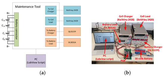
Before describing in details the maintenance tool proposed in this work, it is worth saying that we suppose that the battery is provided with a standard connector to simplify the access to the cell terminals. In this way, a maintenance service operator can verify the battery state and optimize it independently of the BMS integrated in the pack. This assumption is not difficult to satisfy, because any BMS has electrical connections to each cell, at least to measure the cell voltages for safety reasons. Figure 1 shows the general architecture of the low-cost maintenance system tool for a battery with N series-connected cells. It consists of some blocks, among which are the control and measurement unit, the diverter relay-matrix and the management unit.

Figure 1. General architecture of the proposed maintenance tool for a battery composed of N series-connected cells.
The diverter relay-matrix is composed of diverter relays organized in a matrix that allows us to select one specific cell
CX among the
N battery cells. The block has
N differential inputs, one for each cell, and one differential output.
The matrix consists of S diverters organized in Y cascaded layers that are given by (1) and (2), respectively, as initially introduced in [22].
2.2. 16-Cell Relay-Matrix Board Specification
As a case study, the tool architecture shown in Figure 1 was realized for a battery composed of up to 16 series-connected cells. Figure 2a shows the photograph of the relay-matrix board developed and realized for this study. The battery connector has 17 pins to contact the cell terminals and 2 pins for the battery positive and negative terminals. In this way, the measurement of the cell voltages is not affected by the battery current flowing in the power path, because a 4-wire measurement technique is applied. The stack monitor IC bq76PL455A from TI directly measures the voltage on each cell with dedicated voltage sense pins. Instead, the outputs of the current sensors described afterward are read on the two analog AUX ADC inputs of the same IC. It is worth reminding that the cell and the AUX pin voltages are measured with a typical accuracy of ±0.75 mV and ±0.10 mV, respectively. Two Hall-effect ACS711KLCTR-12AB-T devices are used as linear current sensors. These current sensors are very cheap and affordable for the application but their accuracy is rather scarce. The sensor sensitivity is 110 mVA and the accuracy is around 5% when supplied with 3.3 V. The accuracy worsens at higher power supply voltage. For this reason, both the sensors were characterized during the functional testing of the board, and a calibration procedure that corrects the sensor offset and gain errors was applied to the current measurements. The PT571012 and PT271012 devices are used as 4 and 2 Pole Throw (PT) diverter relays, respectively. The relay coil rated voltage is 12 V and the power is 750 mW. They can withstand a maximum continuous current of 6 A, which represents the tool maximum charging or discharging current value. These diverter relays are used to implement the matrix shown in Figure 2b and the safety deviators in the battery-path and cell-path output blocks. The matrix of 30 diverters, obtained using 7 PT571012 and 1 PT271012, is organized in 4 layers according to (2) and (1). The LabView graphical user interface allows the operator to set the relay positions, to check the battery state and to perform specific diagnostic and maintenance tests on the battery. Although the software architecture is beyond the scope of this paper, the source files are available on-line, according to the Open-source philosophy. The experimental characterization and validation of the proposed tool are described in Section 3.
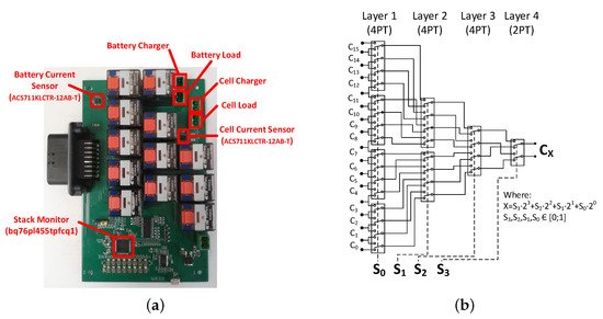
Figure 2. (a) Photograph of the tool relay-matrix board; (b) Relay-matrix architecture for a battery composed of 16 series-connected cells.
3. Maintenance TProol Experimcedurental Validation
3.1. Experimental Tests for the Tool Validation
A battery composed of 16 series-connected second-hand cells was assembled and characterized by using the proposed maintenance tool to verify its functionalities. The cells are LGDBHE21865A from LG Chem. They are cylindrical with a nominal capacity of 2.5 Ah, a voltage range from 2.75 V to 4.2 V and a rated series resistance lower than 20 mΩ. These cells were used in the first life in laboratory investigations characterized by different electrical and environmental conditions. Furthermore, some of them were also abused in some cases. Their different history and aging level make them a perfect example for testing the maintenance tool, and in particular to verify if the tool is able to reveal the most degraded cells in the pack. It is worth reminding that the battery is not equipped with a BMS, because it was assembled and exclusively used for the validation of the maintenance tool.
Figure 3a shows the block scheme of the experimental setup used to carry-out the battery maintenance tests. It consists of the maintenance system, the assembled battery, two Tektronix Keihtley 2420 used as cell charger and load, respectively, a RIGOL DL3031A as battery load, and a TTi QL355TP power supply used as battery charger, as the photograph in
Figure 3b shows. For the sake of clarity, the two 35 V output channels of the QL355TP were series-connected to reach the maximum battery voltage of 67.2 V.
It is worth noting that we used the instruments available in our laboratory for the prototype validation. However, they can be replaced with lower cost ones. The only requirement is the capability of applying static Constant-Current and Constant-Voltage profiles as it will be shown in the next sub-sections.
Figure 3. Experimental set-up used to test a battery pack with 16 series-connected cells. (a) Block scheme; (b) Prototype photograph.
3.2. Battery Maintenance Procedure
The following tests aim to verify the maintenance tool functionalities including the battery cell charge equalization and the identification of the cells residual caSp
acity and serie
s-resistance. This information is fundamental to permit the correct maintenance of a LEV battery pack. Charge equalization maximizes the battery usable capacity [12,14]cifically,
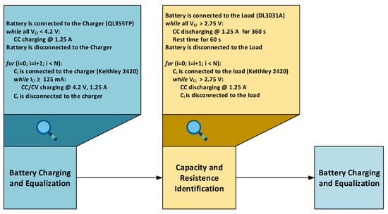
whereas residual capacity and series-resistance asses the cell aging [24]. Specifically, Figure 4 shows the flowchart of the maintenance procedure adopted, which starts with the battery charging and equalization step. To this end, the tool charges the battery by connecting the power supply set with a constant current of 1.25 A. The charging process continues until one cell reaches the upper cut-off voltage of 4.2 V. Then, the battery charger is disconnected and the cell
C0 is selected by the relay-matrix.
C0 is fully charged by connecting to it the Keihtley 2420, which applies the classical Constant Current-Constant Voltage (CC-CV) profile with values of 1.25 A and 4.2 V, respectively. The CC-CV profile continues until the cell charging current falls below 125 mA. Then, the maintenance tool disconnects the cell
C0 and connects the cell charger to the cell
C1. The procedure is repeated for all the cells of the battery pack. Every battery cell is fully charged and balanced with the others at the end of the initialization procedure.
Figure 4. Flowchart of the battery maintenance procedure.
The battery characterization proceeds by using a procedure similar to a Pulsed Current Test (PCT) [
256].
The PCT usually starts from a know battery state such as the fully charged condition and consists of discharge current pulses with specific amplitude and duration separated by a rest period. The series-resistance and the relaxation phenomena of each cell are assessed by acquiring its voltage response. Specifically, the resistance is identified by evaluating the voltage drop due to the current step
[26].
Instead, the relaxation phenomena can be modeled acquiring the cell voltage behavior during the rest period, which can last up to several hours. Since the characterization of the relaxation phenomena is beyond the scope of these tests, the rest time was set to 60 s to reduce the test duration. The amplitude and duration of the current pulse were set to 1.25 A and 360 s, respectively. The current pulses are directly applied to the battery terminals by the electronic load, while the stack monitor simultaneously acquires the voltage of each cell during the test. The PCT continues until one cell reaches the minimum cut-off voltage value of 2.75 V. Since the PCT starts from the fully charged condition of each cell and ends when the cell with the lowest capacity reaches the fully discharged state, the time integration of the current gives the actual residual capacity of the battery, which is the same of the most aged cell. Finally, the cells are individually discharged, one by one, to identify their residual capacity. Here, the relay-matrix sequentially selects and connects one cell to the cell load. This final discharging phase occurs with a constant current of 1.25 A and 2.75 V as cell cut-off voltage. The actual cell capacity is assessed by integrating the cell current and adding the measured charge to the residual capacity of the most degraded cell. The outstanding result obtained with the maintenance tool is the complete characterization of every cell of the battery in terms of the residual capacity and the internal resistance at different values state of charge.
3.3. Battery Maintenance Procedure Results
4. Tool Validation
The battery characterization procedure described above was applied to the assembled battery.
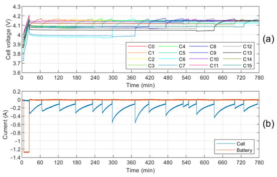
Figure 5 shows the cell voltages together with the currents of the battery and the selected cell, as measured by the stack monitor IC and the calibrated sensors. We note that the battery is first charged with a constant current of 1.25 A (orange track) in
Figure 5b. The charge continues until
C11 reaches the upper cut-off voltage of 4.2 V [see
Figure 5a]. Then, the maintenance tool disconnects the battery charger and connects the cell charger to
C0. The charger applies the CC-CV profile to fully charge the cell (blue track) in
Figure 5b. As soon as the cell current reaches the stop value of 125 mA, the maintenance tool disconnects
C0 and connects
C1 to the charger. The procedure is repeated until all the cells are fully charged in sequence. It should be noted that the cells, initially strongly unbalanced, are all progressively brought to the maximum voltage achieving the complete cell balancing at 100% state of charge. Indeed, the maximum mismatch among the cell voltages is reduced from 247 mV to 35 mV at the end of the balancing phase, as is visible in
Figure 5a.
Figure 5. Cell voltages. (a) battery and cell currents; (b) during the charge balancing phase. The cells are sequentially charged up to the maximum voltage level.
Starting from the battery fully charged and balanced, the resistance and capacity identification is carried-out by exploiting the pulsed current test.
Figure 6 reports the battery current, the cell voltages, and the series-resistances in the diagrams from top to the bottom, respectively. It should be noted that
C6 is the most aged cell as it reaches the minimum cut-off voltage before the others during the ninth pulse. At this point, the maintenance tool stops the PCT to avoid undervoltage on this cell. The time integration of the current allows us to calculate the
C6 residual capacity that results to be 1.14 Ah, a value below 50% of the nominal capacity. As expected,
C6 also shows the highest series-resistance, as seen in
Figure 6c. Thus, the results of the maintenance procedure confirm the capability of the proposed tool to determine the most aged cell, which limits both the maximum battery usable capacity and the power performance.
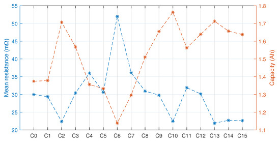
Figure 7 shows the residual capacity of the cells and their series-resistance calculated as the average of the values shown in
Figure 6. The cells with the lowest residual capacities show the highest series-resistance
, confirming the trend found in [27].
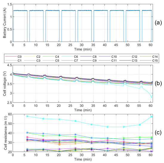
Figure 6. Cell voltages. (a), battery current; (b), and cell series-resistances; (c) measured during the PCT.
Figure 7. Average series-resistance value and residual capacity of each battery cell.
45. DiscusConclusion
The idea of a low-cost battery maintenance tool conceptually described in [
225] has found a practical realization in this work. Specifically, the experimental results
reported in Section 3.3 validate the proposed tool for a battery composed of 16 series-connected lithium-ion cells. In fact, the tool is able to balance the battery pack restoring the optimal condition. This fact will increase the LEV performance without interactions with the BMS that usually is a closed system. Moreover, the tool can completely characterize the battery pack by measuring the actual residual capacity and the series-resistance of each cell. These important features allow a maintenance operator to map the battery state and to identify the most degraded and aged cells that limit the overall battery performance in terms of usable capacity and power capability
[12,13].
Even if the voltage measurements performed by the stack monitor IC apply a 4-wire measurement technique when the cells are charged and discharged from the battery terminals, it should be noted that the stray resistance of the cable that connects the PCB connector to the cells takes part in the measurement when a single cell is charged or discharged.
The
cable resistance should be characterized and taken into account in these last cases.
As shown in Section 3.3, the maintenance tool can selectively charge and discharge either the battery or a specific cell. Thus, it can bring the battery in a desired state and simultaneously apply to all the cells a given current profile. Otherwise, it can separately operate on each battery cell by properly setting the relay-matrix. These capabilities combined with the possibility of simultaneously acquiring all the cell voltages speed-up the battery maintenance procedure if compared to the instruments proposed in [
6,214].
Moreover,
the flexibility is a strength of the proposed tool. It can employ different low-cost laboratory instruments with characteristics suited to the battery under test, and it can easily be managed by a simple PC as shown in
Figure 3. All these features make the proposed maintenance tool appealing in terms of overall cost, particularly if compared with professional characterization tools. Therefore, it simplifies the maintenance procedure supporting and accelerating the
LEVdiffusion.
The most critical drawback that could limit the diffusion of the proposed maintenance tool is the lack in commercial battery packs of a standard connector that directly accesses the cell terminals. However, the large increment of LEVs expected in the next few years [3] might convince the battery producers to apply a standard connector to each battery pack making the diagnostic process easier. Finally, we also remind that the tool hardware and software source files are available as supplementary material and can be downloaded from the link
https://github.com/batterylabunipi/MaintenanceToolForLightElectricVehicles.git (accessed on 6 August 2021), according to the open-source philosophy [
6].
5. Conclusions
This paper describes the development and validation of a low-cost maintenance tool for battery characterization. It optimizes the battery state and characterizes each battery cell without interactions with the inner battery management system. The tool is based on a custom board and common laboratory instruments. It can directly charge and discharge either the battery or a selected cell by using a relay-matrix on the custom board. The realization of a proper diagnostic procedure allows the identification of the series-resistance and the actual capacity of each cell returning a sort of screenshot of the battery cell aging. Furthermore, the battery cell charges can easily be balanced leading to improved battery state and vehicle performance. At the same time, the maintenance tool was developed with low-cost devices to keep the overall cost low and much less than the professional tools. Indeed, the cost of a maintenance tool is key to increase the diffusion of vehicle assistance centers, which will become essential in the next years. In fact, a widely spread network of assistance centers will be required to cope with the huge increment of the battery maintenance operations needed by the e-mobility devices. Therefore, the proposed maintenance tool may reduce the instrumentation cost and simplify the maintenance procedure supporting and accelerating the light electrical mobility diffusion process.
Funding
This research was partially funded by PAR FAS Toscana 2007–2013 (Bando FAR FAS 2014), under agreement n. 4421.02102014.072000022 Project SUMA, by ENEA “Ricerca di Sistema Elettrico-Electrochemical Storage Systems and relevant network interfaces”, and supported by the CrossLab project funded by MIUR “Departments of Excellence” program.
Data Availability Statement
The hardware and software source files of the tool presented in this study are available online and can be downloaded from the link https://github.com/batterylabunipi/MaintenanceToolForLightElectricVehicles.git (accessed on 6 August 2021).
Conflicts of Interest
The authors declare no conflict of interest.
References
- Sachs, C.; Burandt, S.; Mandelj, S.; Mutter, R. Assessing the market of light electric vehicles as a potential application for electric in-wheel drives. In Proceedings of the 2016 6th International Electric Drives Production Conference (EDPC), Nuremberg, Germany, 30 November–1 December 2016. [
- Google Scholar
- ] [CrossRef]
- Carloni, A.; Baronti, F.; Di Rienzo, R.; Roncella, R.; Saletti, R. Open and Flexible Li-ion Battery Tester Based on Python Language and Raspberry Pi. Electronics 2018, 7, 454. [Google Scholar] [CrossRef]
- Babin, A.; Rizoug, N.; Mesbahi, T.; Boscher, D.; Hamdoun, Z.; Larouci, C. Total Cost of Ownership Improvement of Commercial Electric Vehicles Using Battery Sizing and Intelligent Charge Method. IEEE Trans. Ind. Appl. 2018, 54, 1691–1700. [Google Scholar] [CrossRef]
- Vergori, E.; Mocera, F.; Somà, A. Battery Modelling and Simulation Using a Programmable Testing Equipment. Computers 2018, 7, 20. [Google Scholar] [CrossRef]
- Carloni, A.; Baronti, F.; Di Rienzo, R.; Roncella, R.; Saletti, R. Preliminary Study of a Novel Lithium-Ion Low-Cost Battery Maintenance system. In Lecture Notes in Electrical Engineering; Springer International Publishing: Basel, Switzerland, 2021; pp. 241–245. [Google Scholar] [CrossRef]
- Lee, S.; Kim, J. Power Capability Analysis of Lithium Battery and Supercapacitor by Pulse Duration. Electronics 2019, 8, 1395. [Google Scholar] [CrossRef]
- Tarascon, J.M.; Armand, M. Issues and challenges facing rechargeable lithium batteries.
- Nature
-
- 2001, 414, 359–367. [Google Scholar] [CrossRef] [PubMed]
- Brenna, M.; Foiadelli, F.; Longo, M.; Zaninelli, D. e-Mobility Forecast for the Transnational e-Corridor Planning. IEEE Trans. Intell. Transp. Syst. 2016, 17, 680–689. [Google Scholar] [CrossRef]
- Sachs, C.; Burandt, S.; Mandelj, S.; Mutter, R. Assessing the market of light electric vehicles as a potential application for electric in-wheel drives. In Proceedings of the 2016 6th International Electric Drives Production Conference (EDPC), Nuremberg, Germany, 30 November–1 December 2016. [Google Scholar] [CrossRef]
- Brdulak, A.; Chaberek, G.; Jagodziński, J. Determination of Electricity Demand by Personal Light Electric Vehicles (PLEVs): An Example of e-Motor Scooters in the Context of Large City Management in Poland. Energies 2020, 13, 194. [Google Scholar] [CrossRef]
- Petrauskiene, K.; Dvarioniene, J.; Kaveckis, G.; Kliaugaite, D.; Chenadec, J.; Hehn, L.; Pérez, B.; Bordi, C.; Scavino, G.; Vignoli, A.; et al. Situation Analysis of Policies for Electric Mobility Development: Experience from Five European Regions. Sustainability 2020, 12, 2935. [Google Scholar] [CrossRef]
- Carloni, A.; Baronti, F.; Di Rienzo, R.; Roncella, R.; Saletti, R. Open and Flexible Li-ion Battery Tester Based on Python Language and Raspberry Pi. Electronics 2018, 7, 454. [Google Scholar] [CrossRef]
- Babin, A.; Rizoug, N.; Mesbahi, T.; Boscher, D.; Hamdoun, Z.; Larouci, C. Total Cost of Ownership Improvement of Commercial Electric Vehicles Using Battery Sizing and Intelligent Charge Method. IEEE Trans. Ind. Appl. 2018, 54, 1691–1700. [Google Scholar] [CrossRef]
- Di Rienzo, R.; Zeni, M.; Baronti, F.; Roncella, R.; Saletti, R. Passive balancing algorithm for charge equalization of series connected battery cells. In Proceedings of the 2020 2nd IEEE International Conference on Industrial Electronics for Sustainable Energy Systems (IESES), Cagliari, Italy, 1–3 September 2020. [Google Scholar] [CrossRef]
- Baughman, A.; Ferdowsi, M. Double-Tiered Switched-Capacitor Battery Charge Equalization Technique. IEEE Trans. Ind. Electron. 2008, 55, 2277–2285. [Google Scholar] [CrossRef]
- Morello, R.; Di Rienzo, R.; Roncella, R.; Saletti, R.; Schwarz, R.; Lorentz, V.; Hoedemaekers, E.; Rosca, B.; Baronti, F. Advances in Li-Ion Battery Management for Electric Vehicles. In Proceedings of the IECON 2018—44th Annual Conference of the IEEE Industrial Electronics Society, Washington, DC, USA, 21–23 October 2018. [Google Scholar] [CrossRef]
- Jie, L.; Abhinav, S.; Kai, G.; Bhaskar, S.; Wilson, W. An Adaptive Recurrent Neural Network for Remaining Useful Life Prediction of Lithium-ion Batteries. In Proceedings of the Annual Conference of the Prognostics and Health Management Society, Portland, OR, USA, 13–16 October 2010. [Google Scholar]
- Park, H.S.; Kim, C.H.; Park, K.B.; Moon, G.W.; Lee, J.H. Design of a Charge Equalizer Based on Battery Modularization. IEEE Trans. Veh. Technol. 2009, 58, 3216–3223. [Google Scholar] [CrossRef]
- Kim, J.; Shin, J.; Chun, C.; Cho, B.H. Stable Configuration of a Li-Ion Series Battery Pack Based on a Screening Process for Improved Voltage/SOC Balancing. IEEE Trans. Power Electron. 2012, 27, 411–424. [Google Scholar] [CrossRef]
- Kuhn, B.; Pitel, G.; Krein, P. Electrical Properties and Equalization of Lithium-Ion Cells in Automotive Applications. In Proceedings of the 2005 IEEE Vehicle Power and Propulsion Conference, Chicago, IL, USA, 7 September 2005. [Google Scholar] [CrossRef]
- Bui, T.M.N.; Niri, M.F.; Worwood, D.; Dinh, T.Q.; Marco, J. An Advanced Hardware-in-the-Loop Battery Simulation Platform for the Experimental Testing of Battery Management System. In Proceedings of the 2019 23rd International Conference on Mechatronics Technology (ICMT), Salerno, Italy, 23–26 October 2019. [Google Scholar] [CrossRef]
- Wu, H. Hardware-in-loop verification of battery management system. In Proceedings of the 2011 4th International Conference on Power Electronics Systems and Applications, Hong Kong, China, 8–10 June 2011. [Google Scholar] [CrossRef]
- Barreras, J.V.; Fleischer, C.; Christensen, A.E.; Swierczynski, M.; Schaltz, E.; Andreasen, S.J.; Sauer, D.U. An Advanced HIL Simulation Battery Model for Battery Management System Testing. IEEE Trans. Ind. Appl. 2016, 52, 5086–5099. [Google Scholar] [CrossRef]
- Morello, R.; Di Rienzo, R.; Roncella, R.; Saletti, R.; Baronti, F. Hardware-in-the-Loop Platform for Assessing Battery State Estimators in Electric Vehicles. IEEE Access 2018, 6, 68210–68220. [Google Scholar] [CrossRef]
- Di Rienzo, R.; Roncella, R.; Morello, R.; Baronti, F.; Saletti, R. Low-cost modular battery emulator for battery management system testing. In Proceedings of the 2018 IEEE International Conference on Industrial Electronics for Sustainable Energy Systems (IESES), Hamilton, New Zealand, 31 January–2 February 2018. [Google Scholar] [CrossRef]
- Segway-Ninebot After-Sale Assistance. Available online: https://uk-en.segway.com/after-sales-service (accessed on 6 August 2021).
- Vergori, E.; Mocera, F.; Somà, A. Battery Modelling and Simulation Using a Programmable Testing Equipment. Computers 2018, 7, 20. [Google Scholar] [CrossRef]
- Carloni, A.; Baronti, F.; Di Rienzo, R.; Roncella, R.; Saletti, R. Preliminary Study of a Novel Lithium-Ion Low-Cost Battery Maintenance system. In Lecture Notes in Electrical Engineering; Springer International Publishing: Basel, Switzerland, 2021; pp. 241–245. [Google Scholar] [CrossRef]
- Jalakas, T.; Zakis, J. Experimental verification of light electric vehicle charger multiport topology. In Proceedings of the 2015 9th International Conference on Compatibility and Power Electronics (CPE), Costa da Caparica, Portugal, 24–26 June 2015. [Google Scholar] [CrossRef]
- Balagopal, B.; Chow, M.Y. The state of the art approaches to estimate the state of health (SOH) and state of function (SOF) of lithium Ion batteries. In Proceedings of the 2015 IEEE 13th International Conference on Industrial Informatics (INDIN), Cambridge, UK, 22–24 July 2015. [Google Scholar] [CrossRef]
- Lee, S.; Kim, J. Power Capability Analysis of Lithium Battery and Supercapacitor by Pulse Duration. Electronics 2019, 8, 1395. [Google Scholar] [CrossRef]
- Yang, J.; Xia, B.; Shang, Y.; Huang, W.; Mi, C. Improved Battery Parameter Estimation Method Considering Operating Scenarios for HEV/EV Applications. Energies 2016, 10, 5. [Google Scholar] [CrossRef]
- Guarino, A.; Zamboni, W.; Monmasson, E. A battery residual capacity indicator based on the battery internal resistance: An experimental study. In Proceedings of the 2020 2nd IEEE International Conference on Industrial Electronics for Sustainable Energy Systems (IESES), Cagliari, Italy, 1–3 September 2020. [Google Scholar] [CrossRef]