The semi-solid metal (SSM) 5083 aluminum alloy was developed for part manufacturing in the marine shipbuilding industry and including other industries using this material in the manufacture of parts.
- semi-solid metal (SSM) 5083 aluminum alloys
- friction stir welding
- Taguchi technique
- optimized parameter
1. Introduction
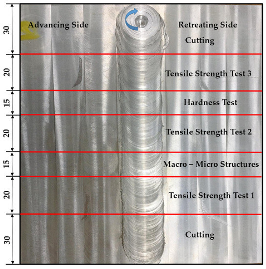
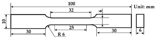
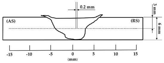
2. Mechanical Property Testing and Metallurgical Structural Inspection
3. Analysis of Tensile Tests, Vickers Hardness Tests, and Microstructural Examination
From the tensile strength analysis of the rotational speed of 1200 rpm, a welding speed of 10 mm/min, and a threaded cylindrical tool pin profile had the maximum tensile strength at 221 MPa, it was found that the defect location of the specimens occurred at the heat-affected zone on the advancing side (AS-HAZ) because the HAZ had the lowest mechanical properties compared to the other areas. This was because fractures often occurred in the HAZ [14], as shown in Figure 4.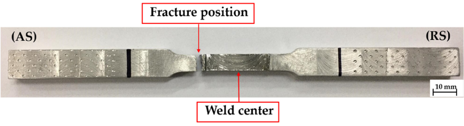 Figure 4. Fracture specimen of tensile test for a rotational speed of 1200 rpm, a welding speed of
10 mm/min, and with a threaded cylindrical tool pin profile.
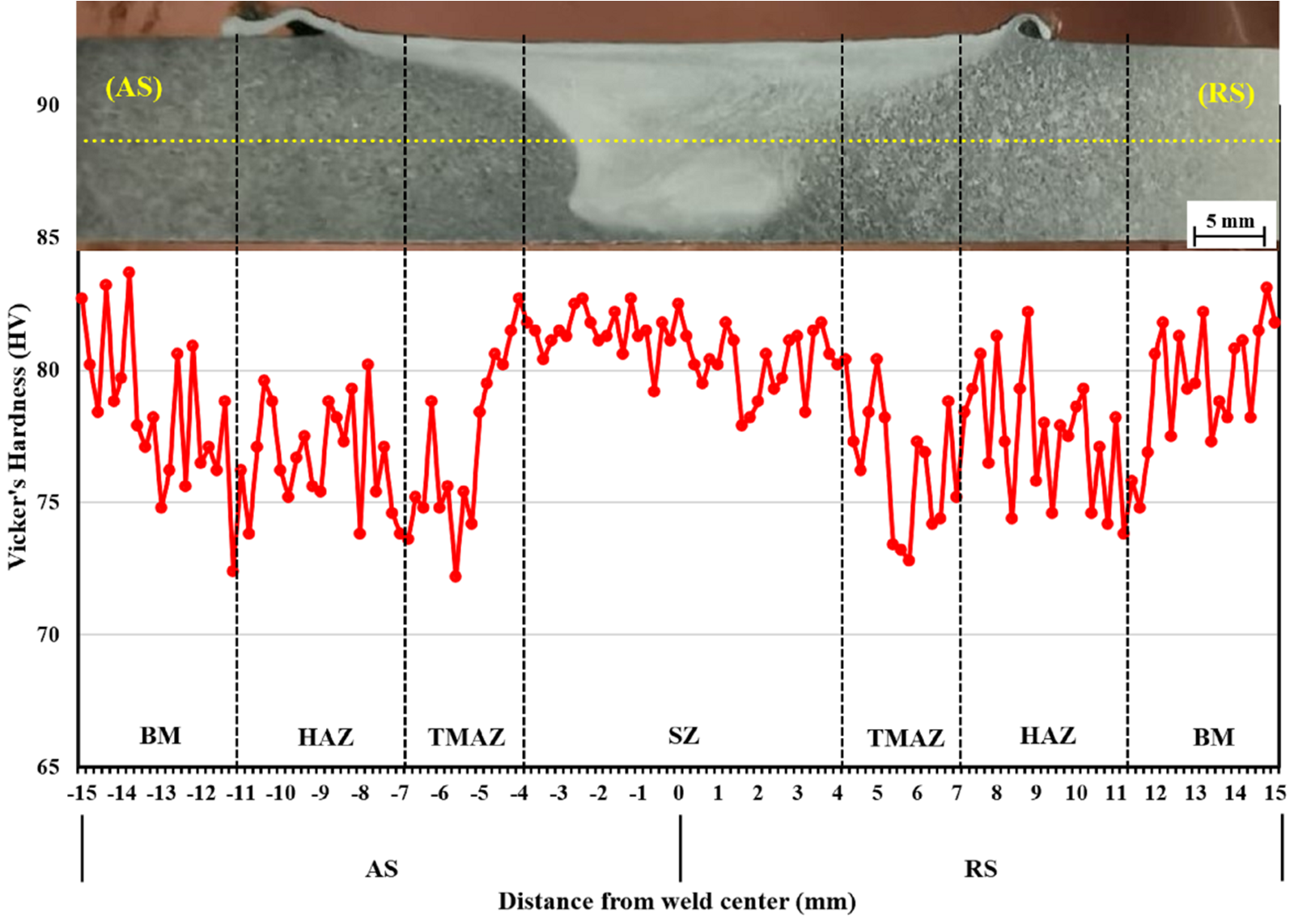
From the analysis of the hardness in the SZ of the rotational speed of 1200 rpm, a welding speed of 10 mm/min, and a threaded cylindrical tool pin profile had the maximum hardness in the SZ at 81.3 HV, which was in line with the hardness values of the base material at 85 HV, because this type of aluminum cannot improve the thermal-mechanical properties and the hardness mechanism is caused by a solid solution [3]. The lowest hardness value occurred at the AS-HAZ, and nearby, at the thermal–mechanically affected zone on the advancing side (AS-TMAZ), as shown in Figure 5.
and a threaded cylindrical tool pin profile.
weld joint, which is relevant to the cracking position of the tensile test specimen, as shown in Figure 4. In Figure 6b, fine grains occurred and there was metal flow from both the AS-TMAZ and the thermal–mechanically affected zone on the retreating side (RS-TMAZ), causing appropriate consolidation. However, there were crack defects and irregular consolidation found in the lower central joint due to the lower heat input from the rotating pin. In Figure 6c, there were many void defects in the AS-TMAZ due to the lower heat input from the rotating pin [15][16]. Moreover, as can be seen in Figure 6d, fine grains occurred and there was metal flow in the RS-TMAZ, causing appropriate consolidation.
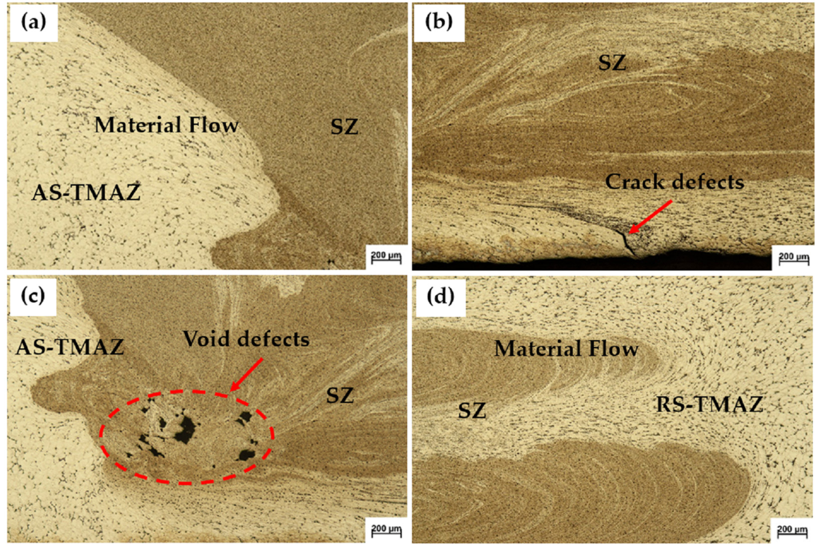
10 mm/min, and with a threaded cylindrical tool pin profile: (a) AS-TMAZ; (b) SZ; (c) pin tip on the
AS; (d) RS-TMAZ.
4. Signal-to-Noise Ratio (S/N Ratio) for the Tensile Strength and the Hardness in the SZ
Signal-to-Noise Ratio (S/N Ratio) The signal-to-noise ratio (S/N ratio) was analyzed for each level of the process parameters, wherein a higher S/N ratio indicates a better weld quality characteristic (the higher, the better) [[17][18]]. Therefore, the optimal process parameter was the one with the highest S/N ratio.
The optimal FSW process parameters for the successful friction stir welding of aluminum alloy SSM 5083 obtained from the tensile strength and the S/N ratio were as follows: A1B1C2: a rotational speed of 1000 rpm, a welding speed of 10 mm/min, and with a threaded cylindrical tool pin profile.
The optimal FSW process parameters for the successful friction stir welding of aluminum alloy SSM 5083 obtained from the hardness in the SZ and the S/N ratio were as follows: A2B1C2: a rotational speed of 1200 rpm, a welding speed of 10 mm/min, and with a threaded cylindrical tool pin profile.
5. Analysis of Variance (ANOVA)
The results were obtained from the ANOVA for the tensile strength and hardness in the SZ. The result proves that the most significant process parameter influencing the tensile strength at a 95% confidence level was welding speed. Contrarily, no parameter (rotational speed, welding speed, or tool pin profile) influenced the hardness in the SZ.
References
- Nakata, K.; Kim, Y.G.; Ushio, M.; Hashimoto, T.; Jyogan, S. Weldability of high strength aluminum alloys by friction stir welding. ISIJ Int. 2000, 40, 15–19.
- Wannasin, J.; Janudom, S.; Rattanochaikul, T.; Canyook, R.; Burapa, R.; Chucheep, T.; Thanabumrungkul, S. Research and development of gas induced semi-solid process for industrial applications. Trans. Nonferrous Met. Soc. China 2010, 20, 1010–1015.
- Mishra, R.S.; Ma, Z.Y. Friction stir welding and processing. Mater. Sci. Eng. 2005, 50, 1–78.
- Kumar, S.; Srivastava, A.K.; Singh, R.K.; Dwivedi, S.P. Experimental study on hardness and fatigue behavior in joining of AA5083 and AA6063 by friction stir welding. Mater. Today Proc. 2020, 25, 646–648.
- Koilraj, M.; Sundareswaran, V.; Vijayan, S.; Koteswara Rao, S.R. Friction stir welding of dissimilar aluminum alloys AA2219 to AA5083 Optimization of process parameters using Taguchi technique. Mater. Des. 2012, 42, 1–7.
- Durga Prasad, M.V.R.; Namala, K.K. Process Parameters Optimization in Friction Stir Welding by ANOVA. Mater. Today Proc. 2018, 5, 4824–4831.
- Raweni, A.; Majstorovic, V.; Sedmak, A.; Tadic, S.; Kirin, S. Optimization of AA5083 Friction Stir Welding Parameters Using Taguchi Method. Teh. Vjesn. Tech. Gaz. 2018, 25, 861–866.
- Bayazid, S.M.; Farhangia, H.; Ghahramania, A. Investigation of friction stir welding parameters of 6063-7075 Aluminum alloys by Taguchi method. Procedia Mater. Sci. 2015, 11, 6–11.
- Shojaeefard, M.H.; Akbari, M.; Khalkhali, A.; Asadi, P.; Parivar, A.H. Optimization of microstructural and mechanical properties of friction stir welding using the cellular automaton and Taguchi method. Mater. Des. 2014, 64, 660–666.
- Javadi, Y.; Sadeghi, S.; Najafabadi, M.A. Taguchi optimization and ultrasonic measurement of residual stresses in the friction stir welding. Mater. Des. 2014, 55, 27–34.
- Gite, R.A.; Loharkar, P.K.; Shimpi, R. Friction stir welding parameters and application: A review. Mater. Today Proc. 2019, 19, 361–365.
- Sillapasa, K.; Mutoh, Y.; Miyashita, Y.; Seo, N. Fatigue Strength Estimation Based on Local Mechanical Properties for Aluminum Alloy FSW Joints. Materials 2017, 10, 186.
- ASTM International. Standard Test Methods for Tension Testing of Metallic Materials E 8M—04. In Annual Book of ASTM Standard; ASTM International: West Conshohocken, PA, USA, 1996; Volume 03.01, pp. 1–24.
- Shahraki, S.; Khorasani, S.; Behnagh, R.A.; Fotouhi, Y.; Bisadi, H. Producing of AA5083/ZrO2 nanocomposite by friction stir processing (FSP). Metall. Mater. Trans. B 2013, 44, 1546–1553.
- Cho, J.-H.; Boyce, D.E.; Dawson, P.R. Modeling strain hardening and texture evolution in friction stir welding of stainless steel. Mater. Sci. Eng. A 2005, 398, 146–163.
- Nandan, R.; DebRoy, T.; Bhadeshia, H.K.D.H. Recent advances in friction-stir welding-process-weldment structure and properties. Prog. Mater Sci. 2008, 53, 980–1023.
- Vijayan, S.; Raju, R.; Subbaiah, K.; Sridhar, N.; Rao, S.R.K. Friction stir welding of Al–Mg alloy-optimization of process parameters using Taguchi method. Exp. Tech. 2010, 34, 37–44.
- D’Urso, G.; Giardini, C. The influence of process parameters and tool geometry on mechanical properties of friction stir welded aluminum lap joints. Int. J. Mater. Form. 2010, 3, 1011–1014.