The compound parabolic concentrator (CPC) is a highly interesting solar collector technology for different low-concentration applications due to no tracking requirement. The CPC with a tubular absorber is the most common type of CPC.
- compound parabolic concentrator
- non-imaging optics
- low-concentrator collector
- tubular absorber
1. Introduction
The compound parabolic concentrator (CPC) is a non-imaging concentrator that utilizes the principle of edge optics. Its history goes back to the late 1950s, when Tabor proposed the concept of the free-tracking concentrating static concentrator [1]. Winston et al. [2] initiated research on non-imaging concentrators in the late 1960s. In 1974, the U.S. Argonne National Laboratory established research on non-imaging concentrators, naming these concentrators as compound parabolic concentrators (CPCs), also establishing the utilization principles of CPCs [3,4][3][4]. The basic design of the CPC employed a flat absorber, but a circular tube groove was later proposed [3]. Different additions to the original CPC design have been proposed such as a secondary compound parabolic reflection [5], an optimal gap between the concentrator and receiver [6], non-imaging condensers [7], internal cusp reflectors with a heat pipe [8], truncated CPCs [9], and W-shaped and multi V-shaped surfaces [10,11][10][11].
Practical design issues such as the use of vacuum technology with the CPC have been analyzed to raise the working temperature [12,13][12][13]. With fluid temperatures up to 100 °C, no vacuum would be necessary [12,13][12][13], but if using a glass cover, a high thermal efficiency could be reached [14]. At low concentration ratios, the effects of the incidence angle on the thermal efficiency could be less than 10% [15], which would be beneficial for stationary applications. Studies to optimize CPCs through different thermal-optical analyses are ample, e.g., a CPC with a tubular receiver [16][17] [16,17] and the reduction of slit optical losses of CPCs [18,19][18][19], efficiency enhancement with a vacuum tube receiver [20], and multiple-row low-concentration CPCs, which could reach a thermal efficiency of 50% at 150 °C [21].
Though CPC research and development has been extensive, in the 1980s in particular, the literature on CPCs with tubular receivers is more limited. Similarly, CPC technology has so far made only a modest market impact, though the potential for low-temperature industrial and residential applications is considerable [22,23,24][22][23][24]. However, the interest in industrial solar low- and intermediate-temperature heat utilization has recently increased [25] [25] for which reason the CPC technology would again be highly relevant. The CPC shows a quite broad application range for solar thermal utilization: Stationary CPCs are applicable for the medium-temperature range (60 °C–150 °C), and tracking CPCs for the medium- and high-temperature range (100 °C–250 °C) [26]. Table 1 shows the positioning of the CPC among the different collector types.
Table 1. Collector types for solar thermal utilization [26].[26]
| Collector Type | Absorber Type | Concentration Ratio | Indicative Temperature Range (°C) |
|---|---|---|---|
| Flat-plate collector (FPC) | Flat | 1 | 30–80 |
| Evacuated tube collector (ETC) | Flat | 1 | 50–200 |
| Stationary compound parabolic collector (CPC) | Tubular | 1–5 | 60–240 |
| Tracking compound parabolic collector (CPC) | Tubular | 5–15 | 60–300 |
| Linear Fresnel reflector (LFR) | Tubular | 10–40 | 60–250 |
| Cylindrical trough collector (CTC) | Tubular | 15–50 | 60–300 |
| Parabolic trough collector (PTC) | Tubular | 10–85 | 60–400 |
| Parabolic dish reflector (PDR) | Point | 600–2000 | 100–1500 |
| Heliostat field collector (HFC) | Point | 300–1500 | 150–2000 |
CPC technology is typically offered with a tubular absorber or flat absorber. The tubular absorber CPC is more suitable for fluid media and for heating a fluid, also yielding a higher heat collection efficiency. Therefore, the focus of this review is on the tubular absorber CPC.
A comprehensive review of the tubular absorber CPC is carried out in this paper. The structure of the paper is as follows: In Section 2, design considerations of the tubular absorber CPC are presented such as the formula curve, gap design, truncation, and deformation of the CPC. In Section 3, the external/internal concentrating tubular absorber CPC is presented. The structure of the tubular absorber CPC is discussed in Section 4. Applications including high-temperature solar thermal utilization, building-integrated solar systems (BISS), photovoltaics (PV)/T systems, refrigeration, hydrogen production, distillation/desalination, and photo-degradation of wastewater are reviewed in Section 5. Conclusions are presented in Section 6.
2. Design Considerations of Tubular Absorber CPC
This section focuses on the issues that need to be considered in the design of the tubular absorber CPC. First, the design curve formula of the CPC is determined. Based on this, the design of gaps and truncation of the CPC will be discussed, reflecting the application for which the CPC is used. It is also necessary to check that the production process is able to match with the allowable optical error of the CPC.
2.1. Formula Curve of Tubular Absorber CPC
The two-dimensional curve of the tubular absorber CPC includes an involute segment and curved segment. There are mainly two types of curves for the tubular absorber CPC (Figure 1), in which the involute segment is similar and the curved segment is different. Winston [4] [4] and Ortabasi et al. [8] [8] proposed the first type of curve and derived its curve formula (Figure 1a). Another type uses a flat CPC curve by replacing the flat receiver with a tubular absorber and an involute segment. The other side of the curve is a part of the parabola (Figure 1b). This paper analyzes the CPC based on the first type of curve, which is called the “ideal concentrator.” It is superior to the second type of curve in terms of height, concentration ratio, and average number of reflections.
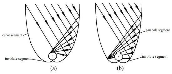
Figure 1. Two types of curves for tubular absorber compound parabolic concentrator (CPC): (a) Involute segment CPC profile; (b) curved segment profile.
A CPC reflects all light within the maximum half acceptance angle θmax to the receiver, where θmax is defined as the maximum angle between the incident light, which can reach the receiver, and the axis of symmetry of the CPC. Each CPC has a theoretical maximum concentration ratio, which can be calculated from θmax (here, 2-D geometry) [4]:
Cmax=1/sinθmax .(1)
The profile curve of a tubular absorber CPC contains an involute segment and a curve segment. The coordinates of the CPC curve are given by Equations (2) and (3) [8].
x=rsint−I(t)cost(2)
y=−rcost−I(t)sint(3)
For involute segments, I(t) is given by Equation (4):
I(t)=rt(0≤t≤π/2+θa)(4)
For curve segments, I(t) is given by Equation (5):
I(t)=r(π/2+t+θa−cos(t−θa))1+sin(t−θa)(π/2+θa≤t≤3π/2−θa)(5)
where r is the radius of the tubular absorber, t is angle variable parameter, and θa is acceptance half angle.
2.2. Gap Design of Tubular Absorber CPC
In practical applications, the CPC absorber and the reflector cannot be in contact as physical contact could cause heat losses through heat conduction and the thermal stress could deform the reflector. In addition, for an external concentrating tubular absorber CPC, contact is not possible, due to the vacuum collector tube used [18]. Therefore, a gap between the bottom of the absorber and the reflector for the tubular absorber CPC is required, which will, however, reduce the concentration ratio and cause some loss of solar radiation. Previous studies have shown that the gap loss of solar energy varies from 5% to 20% [10,11,12,14][10][11][12][14]. Rabl [12] [12] proposed three ways to create gaps: (a) Reducing the radius of the tubular absorber; (b) cutting the sharp corner of the reflector; (c) changing the shape of the absorber (Figure 2). In practice, the method of moving the absorber up is mostly employed (Figure 2d). Mcintire proposed a W-shaped curve instead of the sharp corner of the reflector to avoid gap loss, but this reduced the concentration ratio by 15% [10,11][10][11]. Ortabasi [8] proposed another method to form a gap in the CPC by changing the starting point of the involute.
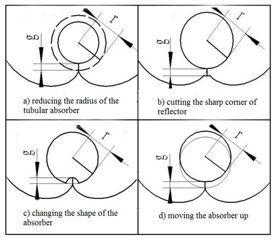
Figure 2. Four ways to create gaps in CPC. (a) Reducing the radius of the tubular absorber; (b) cutting the sharp corner of the reflector; (c) changing the shape of the absorber; (d) moving the absorber up [27].
Wang et al. [27] [27] proposed a tubular absorber CPC with a V-shaped profile at the bottom of the reflector based on the edge-ray principle (Figure 3 and Figure 4). They also studied its key parameters such as geometrical optical efficiency, reflectance, and transmittance and absorption ratio, based on geometrical optics and ray tracing. They showed how to create a gap in the CPC based on the size of the designed CPC gap, and proved that a CPC with a V-shaped profile has a high optical efficiency and good application prospects. The overall efficiency is defined as the product of the relative concentration ratio and the gap efficiency. As the overall efficiency is a relative value, some methods may have an efficiency greater than unity under the condition of reducing the acceptance range.
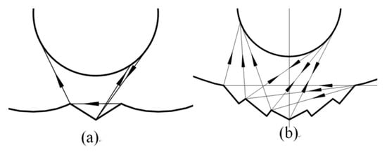
Figure 3. Schematic of the new V-shaped CPC: (a) Single V-shaped CPC; (b) multi V-shaped CPC [27].
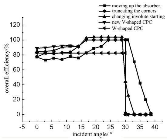
Figure 4. Overall efficiency curves of CPCs with different gap [27].
2.3. Truncation of Tubular Absorber CPC
The complete CPC, especially with a small acceptance angle, has a larger height-to-width ratio and needs more material for the reflector than the general collectors. The reflectors at both ends of the CPC have little effect on the concentration of solar radiation. Therefore, the height of the CPC and the material of the reflector can be reduced by truncating the CPC.
Some researchers have studied the truncation of CPCs [4[4][5][8],5,8], and presented a relationship between the truncation ratio and length to aperture ratios with different acceptance angles. Winston [4] [4] studied the truncation of CPCs based on the average number of reflections. The recommended truncation ratio can be selected based on the Nmin curve in Figure 5, where C is the geometric concentration ratio and Nmin is the reference average number of reflections.
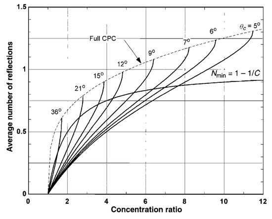
Figure 5. Relationship between concentrating ratio, average number of reflections, and truncation ratio [28].
The truncation ratio is defined as the ratio of hc’ to hc, as shown in Figure 6 [29].
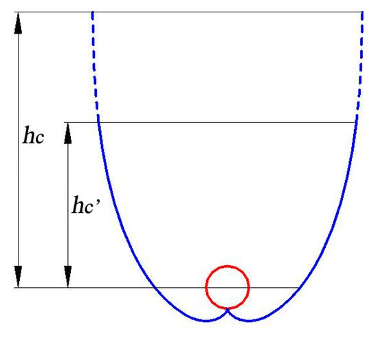
Figure 6. Schematic of truncated CPC.
Yu et al. presented the relationship between the concentrating ratio, the acceptance angle, and the truncation ratio [27,30][27][30] (Figure 7). It can be seen from the figure that the larger the truncation ratio, the greater influence of the truncation on the concentration ratio. When the CPC truncation ratio is 0.4, the loss of concentration ratio is less than 5% [30].
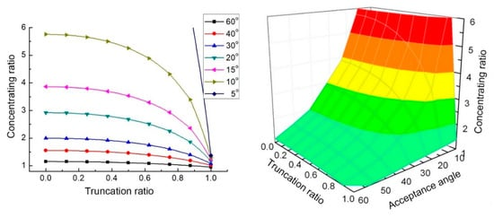
Figure 7. Relationship between concentrating ratio, acceptance angle, and truncation ratio [30].
2.4. Deformation of Tubular Absorber CPC
Errors may occur when the CPC is manufactured and installed, which can affect the concentrating effect of the CPC. Rabl [12] showed that for a tubular absorber CPC with radius r, when the displacement deviation of the receiver or reflector is g, the optical loss is as follows.
L = 1 − 2/π·arccos(g/2r) ≈ g/3r.(6)
Xu et al. [31] [31] studied the deformation of a tubular absorber CPC by the Monte Carlo ray-tracing method, and analyzed the effects of the deformation factor such as the rotation of the reflector, translation of the reflector, and position offset of the absorber. Their research showed that when the rotation and translation deviation of the reflector reached a critical value, the optical loss significantly increased, and the effect of downward, rightward, and leftward offsets of the absorber was greater than that of the upward offsets (Figure 8, Figure 9 and Figure 10, C is the concentration ratio, Ct is the CPC truncation ratio, ω is the rotation angle of the reflector, κ is a dimensionless parameter of reflector translation, λu is a dimensionless number of absorber position offset, and θ is the angle of incident light).
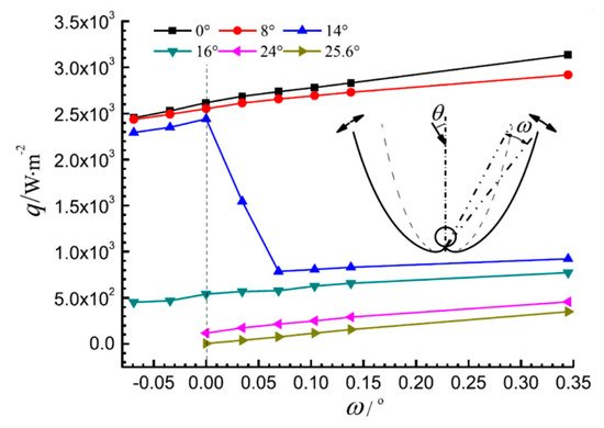
Figure 8. The average heat flux density on the absorber with rotation of the CPC reflector (C = 4, Ct = 0.5) [31].
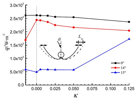
Figure 9. The average heat flux density on the absorber with translation of the CPC reflector (C = 4, Ct = 0.5) [31].
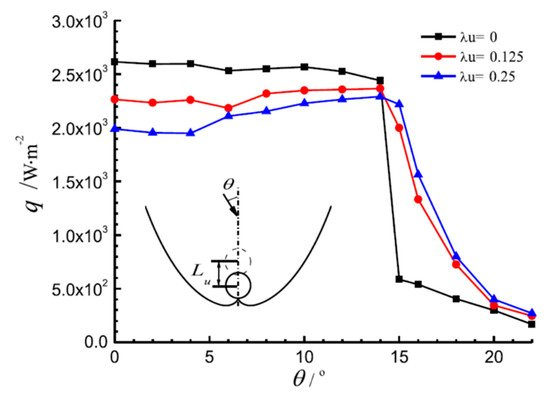
Figure 10. The average heat flux density on the absorber with movement of the absorber (Ct = 0.5) [31].
2.5. Summary
Based on the above analysis, the following conclusions can be made:(1)
For the formula curve of the tubular absorber CPC, it is recommended to choose the curve formula in Figure 1a, and Equations (2)–(5).
(2)The CPC gap should be designed according to the size of the gap given in Table 2.
Table 2. The recommended methods of dealing with the CPC gap.
| g/r | Methods of Dealing with the CPC Gap |
|---|---|
| 0.1–0.51 | new V-shaped CPC prevents the rays that reach the bottom surface of the CPC from escaping and the concentration ratio from reducing |
| 0.51–1 | “V”s CPC can minimize the gap loss |
| <0.2 | little difference between the approaches; truncating the corners is a simple approach |
| >0.6 | changing involute starting point can be chosen for increasing the concentration ratio |
(3)For the truncation of a tubular absorber CPC, ratios in Table 3 are recommended.
Table 3. Recommended truncation ratio.
| Concentration Ratio | Truncation Ratio |
|---|---|
| <2 | 0.6–0.8 |
| 2–5 | 0.4–0.6 |
| >5 | 0.2–0.4 |
(4)The design, processing, and installation errors of the CPC should be limited to a range defined by Monte Carlo ray-tracing calculations, which can significantly reduce the impact of these errors on the CPC performance.
References
- Tabor, H. Stationary mirror systems for solar collectors. Sol. Energy 1958, 2, 27–33.
- Hinterberger, H.; Winston, R. Efficient light coupler for threshold Čerenkov counters. Rev. Sci. Instrum. 1966, 37, 1094–1095.
- Winston, R.; Hinterberger, H. Principles of Cylindrical Concentrators for Solar Energy; Argonne National Laboratory: Lemont, IL, USA, 1974.
- Winston, R. Principles of solar concentrators of a novel design. Sol. Energy 1974, 16, 89–95.
- Rabl, A. Comparison of solar concentrators. Sol. Energy 1976, 18, 93–111.
- Rabl, A. Optical and thermal properties of compound parabolic concentrators. Sol. Energy 1976, 18, 497–511.
- Welford, W.T.; Winston, R. Optics of Nonimaging Concentrators: Light and Solar Energy; Academic Press: Cambridge, MA, USA, 1978.
- Ortabasi, U.; Buehl, W.M. An internal cusp reflector for an evacuated tubular heat pipe solar thermal collector. Sol. Energy 1980, 25, 67–78.
- McIntire, W.R. Truncation of nonimaging cusp concentrators. Sol. Energy 1979, 23, 351–355.
- McIntire, W.R. New reflector design which avoids losses through gaps between tubular absorbers and reflectors. Sol. Energy 1980, 25, 215–220.
- McIntire, W.R. Design parameters for concentrators without gap losses. Sol. Energy 1984, 32, 439–441.
- Rabl, A.; Goodman, N.B.; Winston, R. Practical design considerations for CPC solar collectors. Sol. Energy 1979, 22, 373–381.
- Collares-Pereira, M.; O’Gallagher, J.O.; Rabl, A. Approximations to the CPC-a comment on recent papers by Canning and by Shapiro. Sol. Energy USA 1978, 21, 245–246.
- Hsieh, C.K. Thermal analysis of CPC collectors. Sol. Energy 1981, 27, 19–29.
- Kothdiwala, A.F.; Norton, B.; Eames, P.C. The effect of variation of angle of inclination on the performance of low-concentration-ratio compound parabolic concentrating solar collectors. Sol. Energy 1995, 55, 301–309.
- Khonkar, H.; Sayigh, A. Optimization of the tubular absorber using a compound parabolic concentrator. Renew. Energy 1995, 6, 17–21.
- Fraidenraich, N.; De Lima, R.D.C.; Tiba, C.; Barbosa, E.D.S. Simulation model of a CPC collector with temperature-dependent heat loss coefficient. Sol. Energy 1999, 65, 99–110.
- Oommen, R.; Jayaraman, S. Development and performance analysis of compound parabolic solar concentrators with reduced gap losses–oversized reflector. Energy Convers. Manag. 2001, 42, 1379–1399.
- Oommen, R.; Jayaraman, S. Development and performance analysis of compound parabolic solar concentrators with reduced gap losses—‘V’ groove reflector. Renew. Energy 2002, 27, 259–275.
- Baig, M.N.; Durrani, A.K.; Tariq, A. CPC-trough—Compound parabolic collector for cost efficient low temperature applications. In Proceedings of the ISES World Congress 2007, Vol. I–Vol. V; Springer: Berlin, Germany, 2008; pp. 603–607.
- Buttinger, F.; Beikircher, T.; Pröll, M.; Schölkopf, W. Development of a new flat stationary evacuated CPC-collector for process heat applications. Sol. Energy 2010, 84, 1166–1174.
- Weiss, W.; Rommel, M. Process heat collectors. State Art Task 2008, 33, 1–58.
- Brunold, S.; Frey, R.; Frei, U. Comparison of three different collectors for process heat applications. In Optical Materials Technology for Energy Efficiency and Solar Energy Conversion XIII; International Society for Optics and Photonics: Bellingham, WA, USA, 1994; pp. 107–118.
- Fernández-García, A.; Zarza, E.; Valenzuela, L.; Pérez, M. Parabolic-trough solar collectors and their applications. Renew. Sustain. Energy Rev. 2010, 14, 1695–1721.
- IEA. Solar Energy: Mapping the Road Ahead; IEA: Paris, France, 2019.
- Kalogirou, S.A. Solar Energy Engineering: Processes and Systems; Academic Press: New York, NY, USA, 2013.
- Wang, J.; Yu, L.; Jiang, C.; Yang, S.; Liu, T. Optical analysis of solar collector with new V-shaped CPC. Sol. Energy 2016, 135, 780–785.
- Duffie, J.A.; Beckman, W.A. Solar Engineering of Thermal Processes; John Wiley & Sons: New York, NY, USA, 2013.
- Carvalho, M.J.; Collares-Pereira, M.; Gordon, J.M.; Rabl, A. Truncation of CPC solar collectors and its effect on energy collection. Sol. Energy 1985, 35, 393–399.
- Yu, L. Study on Solar Collector with Compound Parabolic Concentrator. Master’s Thesis, Southeast University, Nanjing, China, 2011.
- Xu, R.; Ma, Y.; Yan, M.; Zhang, C.; Xu, S.; Wang, R. Effects of deformation of cylindrical compound parabolic concentrator (CPC) on concentration characteristics. Sol. Energy 2018, 176, 73–86.