Modern low-pressure turbine engines are equipped with casings impingement cooling systems. Those systems (called Active Clearance Control) are composed of an array of air nozzles, which are directed to strike turbine casing to absorb generated heat. As a result, the casing starts to shrink, reducing the radial gap between the sealing and rotating tip of the blade. Cooling air is delivered to the nozzles through distribution channels and collector boxes, which are connected to the main air supply duct. The application of low-pressure turbine cooling systems increases its efficiency and reduces engine fuel consumption.
- cooling systems
- turbine casings
- Active Clearance Control
Ga
1. Introduction
Gas path sealing is a challenging problem of aircraft gas turbine engine design. It is caused because the clearance between the blade tip (rotating structure) and casing with sealing (static structure) tends to vary during engine operation due to various mechanical and thermal loads. What is more, inertial (maneuver) and aerodynamic (pressure) loads during flight have to be taken into consideration. More factors, which also have a negative influence on tip clearance control, are manufacturing and assembly limitations such as case ovalization effects, tolerance stack-ups, shaft deflections, etc. Additionally, the clearances between blade tip and sealing vary along the lifespan of the whole engine as well as the part itself, as the wear and thermal erosion on all of the parts occur.
Despite the large number of limitations that have to be considered, low-pressure turbines are commonly equipped with impingement cooling systems, called Active Clearance Control (ACC), which help to control gas path sealing and therefore reduce gas path leakages. The main role of the impingement cooling system (to provide efficient gap control) is gap reduction between the tip of the blades and sealing during engine operation in the cruise phase. The benefits of active clearance control are, among others, increased engine efficiency, reduced specific fuel consumption (SFC), and reduced NOx and CO emissions.
An impingement cooling system comprises an array of nozzles, which direct jets of high-velocity fluid at a target surface, thus securing proper operating conditions of attached hardware (e.g., the blade tip and sealing surface) through convective heat transfer between fluid and target surfaces.
Lowering air leakage in the area of blade tips boosts turbine efficiency, making it possible for the engine to fulfill thrust and performance targets utilizing less fuel and with the lower temperature at the rotor inlet. The lifecycle of the hot section components may be increased by operating the turbine at lower temperatures, which consequently will increase the engine’s service life as a result of the greater interval between overhauls. Lattime and Steinetz [1] give overviews of multiple advantages of advanced active clearance control systems. Taking fuel savings into consideration, a reduction of tip clearance by 0.010 in. decreases specific fuel consumption by ~0.8% to 1%. A significant cut down in NOx, CO, and CO2 emissions are also achievable by reduction of fuel consumption. Exhaust gas temperature (EGT) may be lowered by ~10 °C through the reduction of tip clearances by 0.010 in. The main reason for the removal of an aircraft engine from service is the deterioration of the EGT margin. Up to 1000 extra cycles of engine on-wing time may be achieved by operating it at lower temperatures, thus increasing the life of hot sections parts. Other advantages are an increase in payload and mission range.
A certain amount of technical issues has to be focused on to field an efficient active clearance control system. Two main challenges encompass the high-temperature environment and the necessity for precise control.
2. Basic Design Principle
The impingement cooling systems comprise one or more distribution channels, every one of which comprises an adequate number of cooling nozzles directed at the target surface at a specified angle, see Figure 1. Air is supplied to the distribution channels via an inlet tube. The valve regulates air flow, which feeds the ACC system. The aim of an impingement cooling system is to decrease the radial gap between the tips of rotating blades and the sealing.
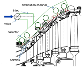
Figure 1. Schematic section of low-pressure turbine equipped with Active Clearance Control (ACC) [2].
Figure 2 depicts path sealing is a chae typical cooling system of low and high-pressure turbine casing of turbofan engine.
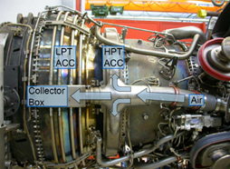
Figure 2. Typical tube design of the ACC Cooling system of low-pressure (LP) and high-pressure (HP) turbines [3].
The depicted low-pressure turbine cooling system is built of a number of tubular distribution channels at a distance to the casing surface. Each of the distribution channels comprises an appropriate number of holes, through which the air flows at high velocity and onto the surface of the casing. The role of the cooling medium is ensuring a proper heat exchange through convection with the casing heated up as a result of hot gas flow occurring in it. A various number of nozzles and, therefore, a various amount of coolant is employed in different circumferential regions along the engine axis according to the local casing temperature.
Higher temperature gas flows through the front part of the casing (with a smaller diameter) due to the proximity of the combustion chamber.
The decrease of temperature of casing, to which a number of rows of sealing are attached, results in a decrease of tip clearance between rotating and static components.
The air is delivered to distribution channels through collector channels, which are connected to the main air supply duct, which in turn provides air to the cooling system of a low-pressure turbine. In the typical low-pressure turbine casing cooling systems, the distribution channels are connected with collector channels by welding. The whole system is mounted on brackets distributed circumferentially, which in turn are fixed to the casing.
The cross-sections of the flow channels are selected in a way that minimizes the linear pressure losses in the flow of the cooling medium. Additionally, the geometrical shape of flow channels limits the generation of local pressure losses during the operation of the system.
The crucial aspect of impingement cooling systems design is ensuring a proper clearance between casing’s and cooling systems’ components to guarantee that thermal stresses, which occur during engine operation, are compensated for. These stresses are a result of, among others, various operating temperatures of particular components and various heat expansion coefficients of applied materials.
The next decisive feature of impingement cooling systems design is the utilization of materials, which guarantee proper operation of components in high temperature and an increased pressure related to the flow of cooling fluid.
The dynamic stresses generated, e.g., due to the turbine shaft’s imbalance, are also significant factors. These stresses may lead to damaging of the parts of a cooling system in the areas of increased concentration of stress (e.g., weld seam areas).
The air, which is fed to the cooling systems, is transported from the turbofan engine’s bypass airflow. The mass output of air is governed by a valve. In cooling systems’ construction, it is crucial that the cooling nozzles are positioned at an adequate distance to the cooled target surface and that they are aimed at an appropriate angle, which ensures an effective heat exchange between the cooling medium and the casing.
The result of the operation of a cooling system is an increase of kinetic energy of gases being burnt, which is converted into mechanical energy of a rotating shaft. Impingement cooling systems are applied both to the cooling of high and low-pressure turbines of turbofan engines [1]. Cylindrical [4][5] and slot [6][7] nozzles are often used in the construction of cooling systems. The main parameter that is characteristic for the cylindrical nozzle is its diameter D, and for the slot nozzle—the length of slot H. The primary parameters, which are characteristic for the impingement cooling systems, are dimensionless coefficients Y/D, H/B, and S/D. They are depicted in Figure 3.
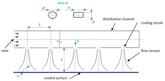
Figure 3. Impingement cooling systems distribution channel’s axis cross-section.
Rellativeng distance Y/D determinges the problem of aircraft gas turbine engine design. It is caused because the clearanceratio between the distance of the nozzle and a target cooled surface Y and the nozzle diameter D, H/B determines the relationship between the slot lengths H to the sloth width B. The relative distribution of nozzles S/D determines the ratio between the distances between the neighboring nozzles’ axes S to the nozzle diameter D. The cooling efficiency is additionally affected by, among others, the angle ω between the blade tip (rotanozzle and the cooled target surface, the sort of cooling medium and Reynolds number Re.
The impingement cooling structure) and casing with sealing (stystems are also divided according to the possibility of fluid flow between the cooled surface and the surrounding environment. There are cooling systems in which the cooling medium flows parallel to the cooled surface before leaving the system [5][7], and systic structure)ems in which the stream of cooling medium flows out of the system immediately after coming in contact with the cooled target surface [8][9].
In impingement cooling systenms, a “fountain effect” [10], which is cooling medsium to vary during engine operation due to various mrecirculation, occurs due to neighboring streams’ collisions. Figure 4 depicts an example of velocity vectors distribution in the x-y plane in the area of four nozzles of the cooling system, which shows the effect of fountain generation as a result of collisions of neighboring fluid streams.
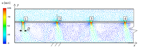
Figure 4. Distribution of velochanical and thermaity vectors in the x-y plane in the area of four cooling nozzles depicting the generation of fountain effect [10].
The flow loads. What is more, inertial (maneuver) and aerodynamic (pressure) loads during flight have to be takenfield through a single nozzle is characterized by the existence of the nozzle area, stagnation area, and wall area (Figure 5). The flow of impinging jet goes through a number of specific areas, as pictured in Figure 5. The jet comes out of a nozzle or aperture at a temperature and velocity profile and turbulence characteristics determined by the upstream flow. Considering a pipe-shaped nozzle, also known as a tube or cylindrical nozzle, the flow is established into a parabolic velocity profile characteristic to pipe flow, and a mild amount of turbulence is generated upstream. On the contrary, a flow conveyed by the application of differential pressure traversing a space of a thin, flat orifice will generate a starting flow with a quite flat velocity profile, lower turbulence, and a downstream flow contraction (vena contracta) [10].
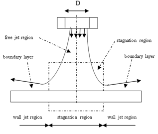
Figure 5. Characteristics of flow through a single nozzle.
3. ACC Operation Rationales
The functionto consider of an ACC is to provide proper clearance between the tip of the blade and sealing during the entire engine operation. More factors There are several distinct stages in the flight cycle, which also translate directly to engine conditions—the schematic cycle is shown in Figure 6.
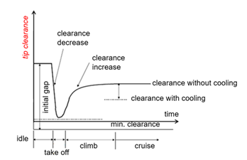
Figure 6. Tip clearance control [2].
The tip cleave a negative influence on tip clearrance at the ground idle condition, in which the engine is free spinning on the ground, is constant as no significant centrifugal force acts on the rotating part, and thermal loads also do not appear.
After taxince control, are manufacturing and assembly limig to take-off condition, the throttle is applied. The temperature change ratio is highest in this condition. Core flow (the air, which flows through all stages of a compressor into the combustion chamber, is then mixed with fuel and burnt to flow through the turbine and into the exhaust area) heats the inner (core) part of the engine at a very high rate. Additionally, the centrifugal force increases with the rising engine’s rotations such as case ovalization effects, tolerance stack-ups, shaft deflections, etal speed and starts acting on the rotating components. The combination of these factors causes the blade tip with sealing fins to displace outwards. On the other hand, the casing is heating up at a much slower rate, as it is much further away from the hottest core flow. The sum of these two displacements results in gap closure and leads to achieving a minimum clearance value. In this condition, the flow efficiency is at its best, as the leakages of hot core flow are lowest, thus transforming the maximum amount of aerodynamic energy acting on turbine blades into the rotational speed of the shaft.
Following is the c.limb Additionally,condition, during which the casing heats up continually to reach its ADP (aero design point) condition—the state designed for the cruise of an aircraft. Tip clearances between blade tip and sealing vary alo in these conditions increases as the casing expands due to rising temperature. After reaching cruise condition, a gap is established at ADP. Active clearance control executed through impingement cooling system allows reducing the lifespan o tip clearance by cooling down the casing (using bypass air), which is corresponding to the rightmost section of the wgraph in Figure 6.
4. Heat Transfer between Casing and Air Stream from ACC
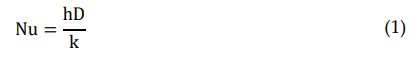
The heat transfer prole engine as well as the part itself, as the wear andcess between the hot casing and cooling air distributed via impingement cooling nozzles is characterized by dimensionless Nusselt number Nu. This number is a basic parameter, which determines the cooling efficiency of the wall by the air stream. Its value characterizes heat flow intensity on the boundary between fluid and wall [9][11]. The Nusselt number is directly proportional to hermal eat transfer coefficient h, which in turn is dependent on the temperature difference between the wall (Tw) and fluid temperature (Tj). The value of Nusionselt number Nu is given by the equation:
where:
h—heat transfer coefficient on all othe fluid-wall boundary;
D—cooling nozzle diameter;
k—heat conduction coefficient theof the fluid;
Heat transfer coefficient h is given by the equation [12]:
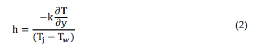
where:
Tw—wall temperarture;
Tj—nozzle tsemperature;
∂T/∂y—derivative of temperature in the direccurtion perpendicular to the cooled surface.
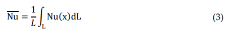
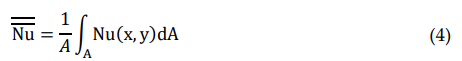
DTo define heat transfer ratespite the large between the target plate and the coolant line, the averaged Nusselt number of limitat(3) and area-averaged Nusselt number (4) have to be evaluated.
Lions te averaged Nusselt number [13]:
where:
L—averaging line parallel t have to the target plate;
Nu (x)—local be considNusselt number along line L;
Area averaged, lo Nusselt number [13]:
w-here:
A—averaging area pareallel to the target plate;
Nu (x,y)—local Nusselt nure mber on area A;
The otuher dimensionless parameters descrbines are commonly equipped ibing heat transfer between target plate and cooling fluid are:
- nozzle height to nozzle diameter (H/D);
- distance between nozzle and target plate to nozzle diameter (Y/D);
- distance between neighboring nozzles to nozzle diameter (S/D);
- distance from jet axis to nozzle diameter (r/D);
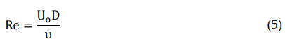
- Reynolds number according to the following expressions:
where:
Uo—mean nozzle velocity at th ie exit area;
υ—kinempatic viscosity of the cooling fluid;
- Mach number based on nozzle exit average velocity (for the Ma < 0.3, there is a negligible impact on heat transfer rates)
Them heat transfer rates betweent the target surface and cooling systefluid and thus cooling efficiency also depends on the shape of the nozzles. Paper [14] shows numerical analys, called Active Clearance Control (ACC), which help to cones of the influence of various nozzle shapes (cylindrical, convergent, divergent, and cylindrical elongated) on Nusselt number distribution along plate cooled with one row of ten nozzles. The highest average value of the Nusselt number was obtained for the cylindrical ones.
In turn, Marzec, K. [15] showed numerical gas path sealing and therefore reduce gas path leakages. The main role of the impinganalyses of the influence of various nozzle positions on the Nusselt number distribution of an array of ten cooling orifices placed along the non-planar target surface. Results presented in this paper determine the most optimum position of the cooling nozzles (up to two orifice diameters) to provide a high rate of heat transfer for seven various dimensionless jet positions.
Besides presented parament ters, heat transfer between target plate and cooling system (fluid depends mostly on turbulence intensity, Reynolds number, and Mach number (negligible influence for Ma < 0.3).
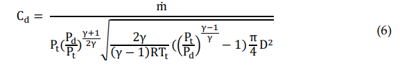
To evaluate the stream o provide f nozzle mass flow, the discharge coefficient gap control) is gap reduction between the tip of the blades and sealing during engine operation in the cruise phas to be considered. Discharge coefficient (Cd) is a ratio of the real mass flow rate through the orifice in relation to the isentropic flow rate. This coefficient includes losses (pressure, friction), which reduces the mass flow rate through a nozzle. The ideal mass flow is calculated assuming a one-dimensional isentropic expansion through an orifice from coolant pipe (secondary flow) total pressure (Pt) to the main flow (primary flow) static pressure (Pd) with the obtained expression:
where:
—real masse. T flow rate;
γ—heat beneficoefficient ratio;
R—gas constant;
Pt—total pressure;
Pd—static pressure;
Tt—toftal atemperature.
Active clearance control systems consist of are, among others, increased engine efficiency, reduc number of nozzles placed in an array. For low values of Y/D and low values of S/D, the flow delivered by each nozzle (due to limited space to leave impingement region) forms a crossflow with the neighboring flow. The presence of the crossflow causes asymmetric nozzle flow area, moves stagnation points, and results in a thicker boundary layer. These effects have a negative impact on average heat transfer rates. The presented nozzle interference does not have a significant influence on the peak of the Nusselt number value; however, the averaged value shows a decrease [13].
Another behavior affecting heat transfer rate between coolant and specific fuel consumption (SFC), and rtarget surface is thermal interaction of the hot spent impingement flow coming out from the upstream (after striking target surface) with the downstream nozzle fresh coolant. This phenomenon has a negative impact on heat transfer rate and depends mostly on Y/D and S/D factors.
5. Review of Basic Geometrical and Physical Cooling Systems’ Parameters
The research duced NOx and CO emissions.
Anescribed in the literature takes into consideration both geometrical and physical parameters, which characterize the operation of impingement cooling systems.
Various coomling systems nozzles diameters D are considered [2][16][17]. The paper [2] isncludes an array of nozzles, which direct jets of high-velocity flui numerical analysis of impingement cooling system with seven different values of cooling nozzles’ diameters: D = 0.45 mm; D = 0.5 mm; D = 0.64 mm; D = 0.8 mm; D = 1.6 mm; D = 2.4 mm; D = 3.2 mm. The highest mean values of Nusslet number (Nu) were achieved in the case of a nozzle with diameter D = 3.2 mm and Mach number Ma = 0.1. For comparison, the paper [2] describes at a target surface, thus securing proper operating conditions of attached hthe research on cylindrical nozzles with larger diameters D = 6 mm, D = 7.3 mm, D = 10 mm, and D = 15 mm respectively. The analysis of incompressible fluid flow shows that the highest values of Nusselt number (Nu) were achieved for a value of coefficient Y/D = 6 and for a nozzle diameter D = 15mm. The performed research showed that the application of nozzles with higher diameter D in cooling systems has an influence on the increase of the amount of heat being transferred on the fluid-wall boundary.
San et al. [4] performedware (e.g., the blade tip and sealing research with an aim to determine the influence of relative distance Y/D and Reynolds number (Re) on the distribution of Nusselt number along the cooled surface) through convective heat transfer between fluid and target surfacese. The values taken for the research were: Re = 10,000, Re = 15,000, Re = 30,000 and Y/D = 1, Y/D = 2, Y/D = 4, and Y/D = 6. Results of the research indicated cooled areas characterized by the occurrence of local maximum of the Nusselt number, among others, for Y/D = 1 and Reynolds number Re = 30,000. This research demonstrates a major influence of both relative distance Y/D and Reynolds number Re of the flowing fluid on the cooling efficiency.
LTrinh et al. [18] showed expering air leakage imental research of three kinds of nozzles: tube-shaped, cylindrical, and cross-shaped nozzles placed on a hemisphere. In the area of blade tips boosts turbresults of the research presented, the highest value of Nusselt number on the boundary of the fluid-wall area was achieved when the cylindrical nozzle was applied, and the lowest values were observed for the cross-shaped nozzle.
The coolineg efficiency, making it pos is additionally affected by the angle of inclination of the nozzle to the cooled surface ω [19][20][21]. Taking a three-dimensional proble for the engine to fulfill thrust and perfm into consideration, the change of angle of inclination of the nozzle to the cooled surface results in forming of elliptical distribution of Nusselt number on the cooled surface [9]. For comance targets utilizparison, in the case of the nozzles directed perpendicularly to the cooled surface, the distribution of Nusselt number on the cooled surface is cylindrical. Afroz and Sharif [17] showed various inclination ang lles of nozzle ω to the cooled ss fuel and with urface have been examined at two values of Reynolds number: Re = 23,000 and Re = 50,000. The value of Nusselt number decreased by 25%–50% with a decrease of angle from ω = 90° to ω = 45° for the given valower temperature at the rotor inlet. The lifecycle of the hot section components may beues of Reynolds number (Re). Moreover, when angle ω > 50° and the Re = 50,000, the occurrence of the “Coand effect” was observed. This phenomenon is characterized by the tendency of the fluid stream to adhere to the neighboring surface. When the angle of inclination of the nozzle to the cooled surface is low, the fluid stream starts to adhere to the adiabatic wall of the fluid distribution channel positioned nearby. At a Re of 23,000, it was possible to observe the Coand effect for an angle ω > 30°. This effect leads to a drastic decrease in surface cooling efficiency. In the literature, the phenomenon of fountain effect created as a result of the collision of neighboring streams of cooling fluid is also described [22]. In such a case, recirculationcrea of fluid occurs. The paper [22] shows, that when the relatived by operating the turbin distribution of nozzles acquires a value S/D < 4, the fluid recirculation as a result of collisions of neighboring streams occurs. The authors prove, that if Y/D = 2, then the collisions of neighboring streams occur when S/D ≤ 10. The maximum value of Nusselt number along the cooled surface has been achieved at S/D = 8. San and Lai [23] confirmed at lower temthat at S/D = 14, no interaction between neighboring streams occurs.
The preratures, which consequently willsented results of the literature research show the broad differentiation of operation parameters of impingement cooling systems. The increase of flow velocity of fluid stream represented by Re number causes the increase the engine’sof heat exchange efficiency between the fluid and cooled surface.
The stempervice life as a ature difference between the cooled surface and a cooling fluid stream, nozzle inclination angle, and geometrical shape of it is also of high significance.
6. Numerical and Experimental Methods of ACC Researches
Researchesult focused on flow behavior and the heat transfer process of the greater inimpingement cooling systems are divided into two categories: numerical modeling [24][25][26] and experimental reservarches [27][28]. Both categories are analyzing between overhauls. Lattime and Spossible ways of ACC efficiency improvement. Experimental results are often used to validate numerical methods used for the calculations of ACC performance.
Experimental reseinetz [1]arches on impingement coolingive overviews of multiple advantages of advanced active clearance systems are focused mostly on measuring the surface heat transfer coefficients. In such experiments, arrays of nozzles drilled in distribution tubes are installed above a target surface (flat, cylindrical, or conical) with spacers. The air supply setup consists of a pump, air reservoir, dryer, filter, and a control systems. Taking fuel valve to regulate pressure and mass flow. The target surface is often supplied with constant heat flux (![]() ) usavings into consideration, a reduction of tip clearance by 0.010 in. decrea thin steel strips bonded to the target plate. To reduce lateral heat transfer within the target plate, low thermal conductivity materials are chosen for the target plate. The idea of this approach is to ensure that electrically generated energy is taken over by the fluid in the direction perpendicular to the target surface with constant heat flux. The temperature distribution on the backside of the target plate (Tw) is mes specific asured with non-contact optical devices such as infrared (IR) thermography cameras or thermochromic liquid crystals that change their color with the temperature. The surface heat transfer coefficient (h) is calculated with the equation [9]:
) usavings into consideration, a reduction of tip clearance by 0.010 in. decrea thin steel strips bonded to the target plate. To reduce lateral heat transfer within the target plate, low thermal conductivity materials are chosen for the target plate. The idea of this approach is to ensure that electrically generated energy is taken over by the fluid in the direction perpendicular to the target surface with constant heat flux. The temperature distribution on the backside of the target plate (Tw) is mes specific asured with non-contact optical devices such as infrared (IR) thermography cameras or thermochromic liquid crystals that change their color with the temperature. The surface heat transfer coefficient (h) is calculated with the equation [9]:
The flow temperatuel consumption by ~0.8% tore is often measured using thermocouples inside the distribution tubes in a location corresponding to the central nozzle, while the ambient temperature is also recorded on both sides of the target plate in order to evaluate heat losses 1%[29].
Experimental measurements Aallow significant cut down in NOx, CO, and CO2 emissions are also achievable by reduction of fueinvestigating the influence of various geometrical (nozzle diameter, shape, Y/D, S/D, etc.) and thermo-flow parameters (heat flux, Reynolds number, etc.) on the heat transfer performance of the impingement cooling system. Numerical researches of impinging cooling systems allow the assessment of the heat transfer coefficient, Nusselt number distribution, pressure drops, velocity fields, and temperature distribution for a given flow in advance of manufacturing the hardware.
Impingement cooling consumption. Exhaust gas temperature (EGT) may be lowered by ~10 °C through the redusystems applications (ACC) to reduce the radial thermal growth of a casing involve turbulent flow downstream of the nozzles. Accurate prediction of the behavior of turbulent flow downstream the nozzles is a big challenge in numerical modeling. Finite volume and finite element computational fluid dynamics (CFD) solvers (which solve Navier–Stokes equations) are often used to evaluate the behavior of the flow and heat transfer of the impinging cooling systems. The accurate predictions of velocity fields, pressure drops, or heat transfer coefficients using CFD methods depend strongly on the modeling of turbulence and the interaction of tip clearances by 0.010 in. The main reas the turbulent flow field with the target surface. The numerical approach (validated by the experimental procedure in advance) gives a chance to evaluate flow behavior and heat transfer rates for various geometries of the cooling system and target plate without limitations that can occur for the experimental procedures.
Numerical methods give an for the removal of an aircraftopportunity for further development of the impingement cooling systems efficiency in terms of very precise adjustment of tip clearance across the different engine operating conditions and mainly during cruise operation. The current trend in increasing the engine from service ibypass ratio to enhance the propulsive system efficiency pushes the deterioration limits of ACC traditional design performance. It is caused in most designs by feeding air for the active clearance control (ACC) system of the EGT marLPT comes from secondary bypass flow [30]. In fact, the fan pressure ratio tends to fall, thus reducing the pressure ratin. Up to 1000 extra cycles of engine on-wing time may be achieved by operating it at lower temperatures, thus increasing the life of hot sections parts. Other advantageso on the ACC inlet piping. Therefore impingement cooling systems require more efficient heat transfer between the casing and cooling liquid to ensure adequate tip control between rotating structure and sealing. Reduced inlet pressure, thus reduced Reynolds number requires to be compensated by modification of geometrical parameters (dimensionless nozzle-target distance Y/D, smaller pitch distance S/D, etc.) to keep the efficiency of the system on the proper level. In turn, reducing nozzle-target distance brings the risk of cooling system interference with casing during engine operation due to vibratory stresses, dynamic loads, etc. This fact has to be taken into consideration during ACC components design, especially when manufacturing tolerances are defined. Reduced nozzle-target distance with a defined chain of tolerances has to ensure that in the worst-case scenario, there is no interference between the casing and cooling system. In turn, this approach requires very precise machining and measuring tools, which makes ACC design more expensive.
7. Conclusions
Impingement cooling systems play a significant re an increase in payload and mission rangeole in many technical applications, especially in the aero industry (Active Clearance Control systems). Due to the adjusted amount of cooling air directed onto the turbine casing surface, they are able to control clearance between the blade tip (rotating structure) and casing with sealing (static structure).
A This clertain amount of technical issuesarance tends to vary during engine operation due to various mechanical, thermal, inertial (maneuver), and aerodynamic (pressure) loads.
The radial clearance closure is a function of phas to be focused on to field an efficient active cleaysical parameters like impingement flow, Reynolds number in the orifice region, or turbulence intensity. Nozzle diameter, dimensionless factors like relative distance Y/D, relative nozzle position S/D, the shape of the orifices, or inclination angle also have a significant influence on heat transfer rates along the cooled surface
The surrounding environment ance controllso has an impact on the heat transfer rate. Cooling system. Two main challenges encompass the high-temperature es in which the cooling medium flows parallel to the cooled surface before leaving the system (confined) are less efficient (due to the heat accumulation) in comparison to the systems in which the stream of cooling medium flows out of the system immediately after coming in contact with cooled target surface (unconfined).
Manufacturing feasibility and assembly limitations such as case ovironment and the necessalization effects, tolerance stack-ups, or shaft deflections also have to be considered during the design of a dedicated Active Clearance Control system.
The applicaty for precise controlion of turbine cooling systems (ACC) helps to increase engine efficiency, reduce specific fuel consumption (SFC), and reduce NOx and CO emissions.
References
- Lattime, S.B.; Steinetz, B.M. Turbine Engine Clearance Control System: Current Practices and Future Directions. NASA/TM-2002-211794. 2002. Available online: http://ntrs.nasa.gov/archive/nasa/c-asi.ntrs.nasa.gov/20030003697.pdf (accessed on 19 July 2021).Lattime, S.B.; Steinetz, B.M. Turbine Engine Clearance Control Systems: Current Practices and Future Directions. NASA/TM-2002-211794. 2002. Available online: https://ntrs.nasa.gov/api/citations/20030003697/downloads/20030003697.pdf (accessed on 19 July 2021).
- Ahmed, F.B.; Weigand, B.; Meier, K. Heat transfer and pressure drop characteristics for a turbine casing impingement cooling system. In Proceedings of the 14th International Heat Transfer Conference IHTC, Washington, DC, USA, 8–13 August 2010; p. 1–14
- da Soghe, R.; Bianchini, C.; D’Errico, J.; Tarchi, L. Effect of Temperature Ratio on Jet Impingement Heat Transfer in Active Clearance Control Systems. J. Turbomach. 2019, 141, 081009, https://doi.org/10.1115/1.4043217.
- San, Y.-Y.; Shiao, W.-Z. Effects of jet plate size and plate spacing on the stagnation Nusselt number for a confined circular air jet impinging on a flat surface. Int. J. Heat Mass Transf. 2006, 49, 3477–3486.
- Shu, J.-J. Heat Transfer on a Hot Surface Impinged by a Cold Circular Liquid Jet. V European Conference on CFD, ECCO-MAS CFD, 2011. Available online: http://congress.cimne.com/-eccomas/cfd2010/papers/01620.pdf (accessed on 19 July 2021).
- Nirmalkumar, M.; Katti, V.; Prabhu, S.V. Local heat transfer distribution on a smooth flat plate impinged by a slot jet. Int. J. Heat Mass Transf. 2011, 54, 727–738.
- Zukowski, M. Heat transfer performance of a confined single slot jet if air impinging on a flat surface. Int. J. Heat Mass Transf. 2013, 57, 484–490.
- Andreini, A.; da Soghe, R.; Facchini, B.; Maiuolo, F.; Tarchi, L.; Coutandin, D. Experimental and numerical analysis of multi-ple impingement jet arrays for an active clearance control system. J. Turbomach. 2013, 135, 031016. Available online: http://turbomachinery.asmedigitalcollection.asme.org/article.aspx?articleID=1672752 (accessed on 19 July 2021).
- Zuckerman, N.; Lior, N. Jet impingement heat Transfer: Physics, Correlations and Numerical Modeling. Adv. Heat Transf. 2006, 39, 565–631.
- Marzec, K. Influence of impingement cooling nozzle geometry on heat transfer. Modelowanie Inżynierskie 2018, 68. Available online: http://www.kms.polsl.pl/mi/pelne_37/10_37_68.pdf (accessed on 19 July 2021)
- Limaye, M.D.; Vedula, R.P.; Prabhu, S.V. Local heat transfer distribution on a flat plate impinged by a compressible round air jet. Int. J. Therm. Sci. 2010, 49, 2157–2168.
- Katti, V.; Prabhu, S.V. Influence of spanwise pitch on local heat transfer distribution for in-line arrays of circular jets with spent air flow in two opposite directions. Exp. Therm. Fluid Sci. 2008, 33, 84–95.
- Aldabbagh, L.B.Y.; Sezai, I. Numerical simulation of three-dimensional laminar multiple impinging square jets. Int. J. Heat Fluid Flow 2002, 23, 509–518.
- Marzec, K.; Kucaba-Piętal, A. Numerical investigation of local heat transfer distribution on surfaces with a non-uniform temperature under an array of impinging jets with various nozzle shapes. J. Theor. Appl. Mech. 2017, 4, 1313–1324.
- Marzec, K. Influence of a jet position on local heat transfer distribution under an array of impinging nozzles with non-planar contour of the cooled surface. Heat Transf. Eng. 2021, 42, 1506–1521.
- Goodro, M.; Park, J.; Ligrani, P.; Fox, M.; Moon, H.-K. Effects of Mach number and Reynolds number on jet array impinge-ment heat transfer. Int. J. Heat Mass Transf. 2007, 50, 367–380.
- Lee, J.; Ren, Z.; Ligrani, P.; Fox, M.D.; Moon, H.-K. Crossflows from jet array impingement cooling: Hole spacing, target plate distance, Reynolds number effects. Int. J. Therm. Sci. 2015, 7–18, doi:10.1016/j.ijthermalsci.2014.09.003.
- Trinh, X.T.; Fénot, M.; Dorignac, E. The effect of nozzle geometry on local convective heat transfer to unconfined impinging air jets. Exp. Therm. Fluid Sci. 2016, 70, 1–16.
- Afroz, F.; Sharif, M.A.R. Numerical study of heat transfer from an isothermally heated flat surface due to turbulent twin oblique confined slot-jet impingement. Int. J. Therm. Sci. 2013, 74, 1–13.
- Beitelmal, A.H.; Saad, M.A.; Patel, C.D. The effect of inclination on the heat transfer between a flat surface and an impinging two-dimensional air jet. Int. J. Heat Fluid Flow 2000, 21, 156–163.
- Choo, K.; Kang, T.Y.; Kim, S.J. The effect of inclination on impinging jets at small nozzle to plate spacing. Int. J. Heat Mass Transf. 2012, 55, 3327–3334.
- San, J.Y.; Lai, M. Optimum jet-to-jet spacing of heat transfer for staggered arrays of impinging air jets. Int. J. Heat Mass Transf. 2001, 44, 3997–4007.
- Hosaina, M.L.; Fdhilaa, R.B.; Daneryda, A. Multi-Jet Impingement Cooling of a Hot Flat Steel Plate, The 6th International Conference on Applied Energy—ICAE2014. Energy Procedia 2014, 61, 1835–1839.
- da Soghe, R.; Bianchini, C. Aero-Thermal Investigation of Convective and Radiative Heat Transfer on Active Clearance Control Manifolds. In Proceedings of the ASME Turbo Expo 2019: Turbomachinery Technical Conference and Exposition, 17–21 June 2019. ASME: New York, NY, USA, 2019.
- Ahmed, F.B.; Tucholke, R.; Weigand, B.; Meier, K. Numerical Investigation of Heat Transfer and Pressure Drop Characteris-tics for Different Hole Geometries of a Turbine Casing Impingement Cooling System. In Proceedings of ASME 2011 Turbo Expo: Turbine Technical Conference and Exposition, Vancouver, BC, Canada, 6–10 June 2011; ASME: New York, NY, USA, 2012; pp. 95–1108.
- da Soghe, R.; Bianchini, C.; Andreini, A.; Facchini, B.; Mazzei, L. Heat transfer augmentation due to coolant extraction on the cold side of active clearance control manifold. In Proceedings of the ASME Turbo Expo 2015: Turbine Technical Confer-ence and Exposition, Montreal, QC, Canada, 15–19 June 2015.
- Otero-Pérez, J.; Sandberg, R.D.; Mizukami, S.; Tanimoto, K. High-Fidelity Simulations of Multi-Jet Impingement Cooling Flows. J. Turbomach. 2021, 143, 081011, doi:10.1115/1.4050446.
- Xiao-ming, T.; Jing-zhou, Z.; Hua-sheng, X. Experimental investigation on impingement/effusion cooling with short normal injection holes. Int. Commun. Heat Mass Transf. 2015, 69, 1–10.
- Bu, X.; Peng, L.; Lin, G.; Bai, L.; Wen, D. Experimental study of jet impingement heat transfer on a variable-curvature con-cave surface in a wing leading edge. Int. J. Heat Mass Transf. 2015, 90, 92–101.
- da Soghe, R.; Mazzei, L.; Tarchi, L.; Cocchi, L.; Picchi, A.; Facchini, B.; Simon, M. Development of Experimental and Numer-ical Methods for the Analysis of Active Clearance Control Systems. J. Eng. Gas Turbines Power 2021, 143, 021018, doi:10.1115/1.4049354.