The oscillatory spinning drop method has been proven recently to be an accurate technique to measure dilational interfacial rheological properties. It is the only available equipment for measuring dilational moduli in low interfacial tension systems, as is the case in applications dealing with surfactant-oil-water three-phase behavior like enhanced oil recovery, crude oil dehydration, or extreme microemulsion solubilization. Different systems can be studied, with this method with the lower density phase as the spinning drop, i.ebubble-in-liquid, oil-in-water, microemulsion-in-water, oil-in-microemulsion, includingand systems with the presence of complex natural surfactants like asphaltene aggregates or particles. The technique allows studying the characteristics and properties of water/oil interfaces, particularly when the oil contains asphaltenes and when surfactants are present. We have found that using the oscillating spinning drop method to measure interfacial rheology properties can help make precise measurements in a reasonable amount of time. This is of significance when systems with long equilibration times, e.g., asphaltene or high molecular weight surfactant-containing systems are measured, or with systems formulated with a demulsifier which is generally associated with optimum formulation and a low interfacial tension.
- interfacial rheology
- spinning drop
- crude oil
- asphaltenes
- dilational
1. ThInte Oscillatory Spinning Drop Apparrfacial tension as an energy per unit areat
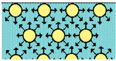
Interfacial tension originates due to the attraction force of the molecules at the interface with other molecules of the same type inside the fluid. This phenomenon is represented in Figure 1, indicating that the smaller the interface area, the lower the force. Therefore, there is an excess energy at the interface, so that minimal energy is attained by minimizing the interfacial area, and therefore, the interface of the liquid tends to contract.
Figusre 1. The interfacial molecules generate a net force towards the bulk of the fluid.
The effect oscillatorf these contraction forces gives rise to interfacial tension, allowing the interface to be stable and to adopt geometries that minimize the interfacial area [1,2].
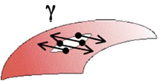
Two definitions can help understand the phenomenon of interfacial tension. The first one, a mechanistic one, refers to the natural tendency of a spinning drop equifluid phase to reduce its interface. Any attempt to increase its area requires the performance of a work, shown schematically in Figure 2. In such a case, the interfacial tension can be described through a tension force F acting tangentially through a length of the perimeter l, or through the work, dW originated by the force F, which acts tangentially to the interface through a differential element dA of the interfacial area. This can be expressed quantitatively as [2]:
γ = F/2L and γ = dW/dA (1)
where γ is the interfacial tension.
Figure 2. Force per unit length to keep the "lip" closed [2].
The second definition, a thermodynamic one, relates the work necessary to modify the area given by γdA. It also considers the work necessary to generate any volume change -PdV, where P is the pressure in each phase and V is the systement 's total volume. Therefore, the total work done in the closed system is:
dW = - P dV + γ dA (2)
and, expressed in terms of Gibbs free energy for a multicomponent system, it is:

which indicas builtes that to minimize Gibbs energy at a constant temperature, pressure and composition, it is necessary to minimize the interfacial area.
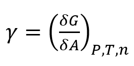
The dimensions of the a interfacial tension are of a physical force per unit length [F/L] (e.g., mN/m)2, acting on a fluid intecade arface, or units of energy per unit area [E/A] (e.g., mN/m or dyne/cm) required to generate such an interface [1,3].
Interfacial tension is what causes the interfaces to be curved. In such circumstances, a vector of a net force tangent to in the the interface is generated, influencing the pressure forces within the bulk of the fluid. At the beginning of the 19th century, Laplace and Young considered the equilibrium state of contiguous fluid phases separated by a curved interface, independently discovering the basic capillary equation, also known as the Young-Laplace equation [1]:
ΔP = γ (1/R1 + 1/R2) (5)
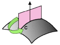
where Δp is the pressure difference along with the curved interface, γ is the interfacial tension, and R1 and R2 are the main curvatures (the largest and the smallest produced by a cut from the normal plane to the interface, shown in FIigure 10), which are approximated to the mean curvature H through the equation:
H = 1/R1 + 1/RP2 (6)
using, in this case, the general equation [2]:
Δp = γ H (7)
As a consequence of the Laplaboratoryce equation, in neglected gravity, the bubbles and droplets assume a spherical shape in equilibrium and the curved interfaces ascend through capillaries.
Figure 3. The average curvature is obtained from the maximum and minimum curvatures R1 and R2 of the cuts with a plane normal the co the surface
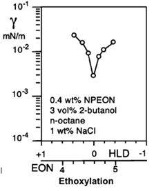
There are two cases in which interfaciallaboration of the CITEC tension measurement is essential in liquid-liquid systems containing interfacially active solutes. The first one is the determination of interfacial tension when the system has reached equilibrium. This value is related to the behavior of the interface after the phenomena of diffusion, adsorption of surfactants, and saturation of the interface have occurred, which is essential for practical purposes in the study of the relationship between the physicochemical formulation and a one-dimensional formulation scan of salinity, EON, EACN, temperature, etc. The interfacial tension at equilibrium is used in this practice to determine the optimal formulation HLD = 0, where it is known that a pronounced minimum of the interfacial tension is found. Figure 4 presents the particular case of an EON scan with a low interfacial tension at equilibrium where the optimal formulation HLD = 0 is attained.
Figure 4. Measurement of interfacial tension at equilibrium in an EON formulation sweep where the application determines the minimum interfacial tension, where the optimal formulation HLD = 0 is found, the measurements were taken with a spinning drop tensiometer [4].
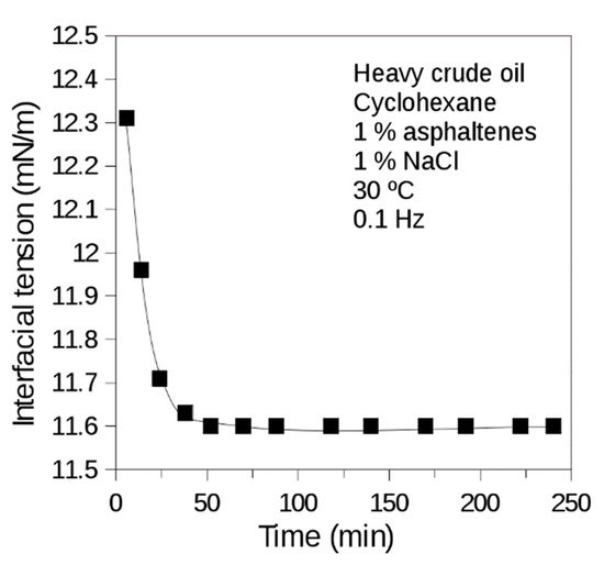
Figure 5 case refers to the measurement of dynamic interfacial tension. There is a time-ULdependent variation of the newly created interface interfacial tension, which is not initially found at the equilibrium composition of the two immiscible phases. A worksfter the surfactant's redistribution in the two phases through diffusion and adsorption, the steady-state is reached. This method is generally used in studies where the adsorption kinetics of surfactants is important [1,5].
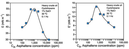
Two cases can be modeled throp, based on the oscillatough the measurement of dynamic interfacial tension. Firstly, when surfactants that are reversibly adsorbed are present, adsorption kinetics can be mathematically adjusted to the Ward and Torday model [6]. Secondly, when the surface-active substances that are irreversibly adsorbed (e.g., proteins and asphaltenes) exhibit adsorption kinetics which can be adjusted to a bi-exponential model of two parameters. The first one (t1) relates to diffusion and adsorption of the molecules at the interface, and the second one (t2) indicates the time delay at which the reorganization of the molecules irreversibly adeformation of a spinsorbed at the interface occurs [7,8]. Dynamic interfacial tension measurements characteristic of systems containing asphaltenes are presented in Figure 5.
Figure 5. Dynaming dropc interfacial tension of brine (1% NaCl)-heavy crude oil diluted in cyclohexane (1% asphaltenes) system. Heavy Venezuelan crude oil of 8° API with high asphaltene content (17 wt%) diluted in cyclohexane. T = 30 °C. Measurement made with the oscillating spinning drop equipment.
2. The Gibbs-Marangoni effect
The generation of [21]surfactant concentration gradients at the interface by the liquid flow in the film between two drops outwards due to drainage produces the Gibbs-Marangoni effect [9]. This flow apparatus can be used to perform removes a part of the surfactant from the interface, creating a non-uniform concentration across it and generating a non-uniform decrease of interfacial film thickness, creating thinner local regions and others of greater thickness. This implies an increase in the interfacial area in the thinner areas and hence a decrease in surfactant concentration. The surfactant concentration gradient at the interface results in the formation of interfacial tension gradients. This leads to a flow of liquid along with the interface from the low interfacial tension zone to the high interfacial tension zone, opposing drainage of the film between drops and contributing to return the film to its original uniform thickness. The net result is a decrease in the thinning rate of the film and, consequently, greater persistence of the interfacial film separating the droplets that make up the emulsion [10]. Therefore, the Gibbs-Marangoni effect delays the drainage of the film due to the generated interfacial rheologtension gradient. The surfactant molecules are swept to the droplet edges, generating the surfactant concentration and interfacial tension gradient, which causes a net force to be present, which is opposite to the drainage of the interfacial liquid film [11].
In terms of interfacial rheology, the measurements of both low and ultraloGibbs-Marangoni effect can also occur if the interface expands or contracts. In such a case, the interfacial tension in this zone will change with respect to its equilibrium value, thus generating interfacial tension gradients [12]. Furthermore, such tension gradients will oppose the drainage of the inter-drop fluid because they move to the interface that opposes the thinning of the liquid film to restore the state of uniform interfacial tension. In other words, this will cause the interface to behave elastically. These interfacial tension gradients are the ones that generate the presence of shear and dilational elasticities at the interfaces (properties that will be defined later) and are quantified with a dimensionless number, the Marangoni number, M = E/γ, where E is the interfacial elasticity and γ is the interfacial tension [9,13].
3. Interfacial tension measurement methods
Equilibrium or dynamic interfacial tensions can be measured with interseveral methods. These can be divided into five groups or techniques [1]:
- Techniques for measuring interfacial tension with microbalances; among these are Wilhelmy's plaque and Nouy's ring.
- Methods to determine directly IFT through the measurement of capillary pressure, the most frequently used being the maximum bubble pressure.
- Techniques based on the balance between interfacial tension forces and the variation liquid volume, including the capillary rise and drop volume.
- Techniques based on the measurement of drop deformation by gravity for a fixed volume, the most important one being the pendant drop tensiometer.
- Techniques in which the deformation of the droplets is generated due to centrifugal forces. These are used to measure ultra-low interfacial tensions, and the most widely used is the spinning drop tensiometer.
Most of these methods cacial tensionsn only be used in systems with tensions greater than one mN/m and have accuracies of approximately 0.1 mN/m. One of the most widely used is the pendant drop method because of its flexibility and ease of measurement of both equilibrium and dynamic interfacial tension. In addition, the availability of high-resolution cameras and computational programs have allowed analysis of the drop profile and the computation of interfacial tension using mathematical methods through the Young-Laplace approximation.
However, these techniques cannot be used for low or ultra-low interfacial tensions because in such cases, the drop elongates too much and detaches. This prevents its use in systems that require an optimal formulation close to HLD = 0.
The equipment used in cases where there is low interfacial tension is the spinning drop tensiometer-rheometer which has excellent flexibility and is particularly useful in applications of improved oil recovery and, as the present work demonstrates, in oil dewatering and water-in-oil emulsion breaking. In addition, when used with high-speed cameras and computer programs, both equilibrium and dynamic interfacial tensions can be measured [14].
4. The Spinning Drop Method
The spinning drop technique has been extensively used to study surfactant-oil-water (SOW) systems since the 1970s when it was low as 1used at the University of Texas to measure the very low interfacial tension required for enhanced oil recovery (EOR) [15–18]. Vonnegut [19] demonstrated the theoretical basis for the measurement in a pioneering work, based on the geometry of an elongated liquid drop, which is located inside a rotating capillary containing the other liquid phase. Equation (10−4) was proposed to calculate the interfacial tension for an elongated quasi-cylindrical drop [20]:
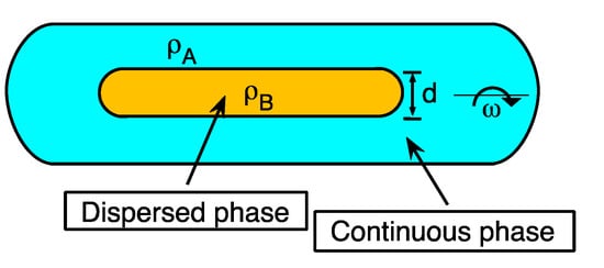
γ = Δρ ωrot2 d3/32 (10)
where γ is the interfacial tension in mN/m, d is the cylindrical droplet diameter in mm, Δρ is the difference of the densities of the two phases in g/mL, and ω the angular velocity in rev/msec [21]. These parameters are depicted schematically in Figure 6. The method consists of placing the surfactant-oil-water systems in test tubes at a known water-oil relationship (usually WOR = 1). This is criti and then pre-equilibrate before the tension measurement (at least for 24 h) [16,22]. Then, the continuous (denser) and dispersed (less dense) phases are placed inside the capillary, inserted in the spinning drop tensiometer.
Figure 6. Spinning drop in the tensiometer capill wheary indicating the parameters necessary to calculate interfacial tension: the densities of the two phases ρA and ρB, the drop diameter d, and the rotational velocity ω.
This method is particularly interesting because it can measure very low interformulation is at or close to oacial tensions (lower than 1 mN/m), which cannot be performed in the simples Du Nouy ring or Wilhelmy plate methods. In sophisticated pendant drop equipment, often used in laboratories, the droplet detaches from the needle at interfacial tensions lower than 1 mN/m, thus excluding such apparatus for oscillating methods [23,24]. The method was recently revisited, indicating the accuracy and flexibility that still allows [25]
5. Interfacial rheology measurement methods
The equipmentimum for interfacial rheology measurement is classified in shear and dilational methods. The most [27][28][31]frequently used shear methods are the channel viscometers and the disc rheometers, and among them, the bicone rheometer is the most frequently used one. Among the dilational methods are surface wave methods mainly used to perform interfacial rheology of air/water systems, and droplet sudeformation methods mainly used in oil/water systems [16,17].
5.1 The two deformation cases: Interfacial shear and dilational rheology
There are presently two basic points of view to determine 2D interfacial rh aeological properties: the shear rheometry, on the one hand, and the other, the dilational rheometry [1].
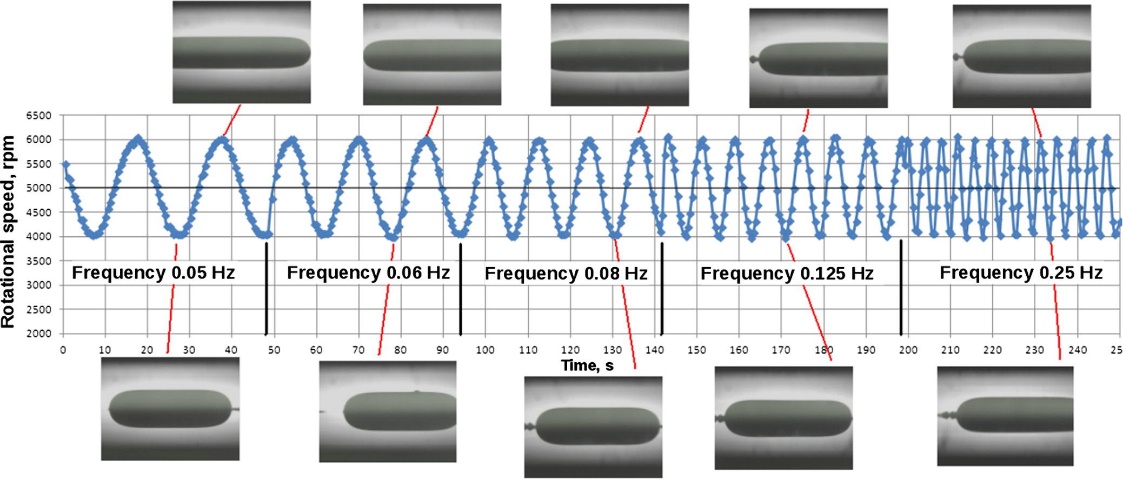
In the first enhanced oil recovery or crude dehydration applicationscase, the perturbation is created at the interface in an interfacial film, either by stationary rotation of a solid in contact with the surface or by periodic oscillations. The processing of the measured torque dependence on the interfacial deformation is based on the analysis of dynamic equations that result in the values of rheological 2D shear parameters, such as shear viscosity and elastic shear modulus. The 2D shear viscosity may further depend on the deformation rate and fluid bulk and may exhibit a non-Newtonian behavior. In the second case, the dilational rheometry, the perturbation is created through the oscillatory expansion and compression of the drop interface where the interfacial area of the surfactant-coated film is subject to changes that generate gradients in the interfacial tension, a phenomenon represented [29][30]in Figure 7. The Dataprelationship between stress and interfacial area changes makes possible the calculation of 2D dilational interfacial rheological parameters, viz. viscosity, and dilational modulus.
The existence of interfacial tension gradients that generate shear and dilational elasticitysics has available an oscillatin at interfaces with adsorbed surfactants is a phenomenon related to the Gibbs- Marangoni effect. In addition, interfacial rheological stresses of a viscous nature — related to shear and dilational interfacial viscosities — may be present and generally occur at interfaces with adsorbed surface-active substances having intra- and intermolecular interactions, as well as interactions with the bulk of the fluid producing resistance to deformation.
These interfacial viscosities create a dissipation effect, similar to viscosity in the bulk of the fluids, in the three-dimensional zone near the fluid interface. Dilational interfacial viscosity comprises both shear and dilation stresses; this is why dilational interfacial viscosities have greater svalues than shear ones and can be measured more easily [2].
Figure 7. Expansinning drop eon and contraction of the interface in dilational interfacial rheology,. The area changes generate variations in the surfactant-coated film, which generates an interfacial tension gradient. In this case, the periodic sinusoidal variation of the rotational speed versus time is from an experiment with an oscillating spinning drop apparatus. Microphotographs obtained at points of minimum and maximum interfacial area are observed. Each point corresponds to a measure of tension and interfacial area.
5.2 Shear interfacial rheology
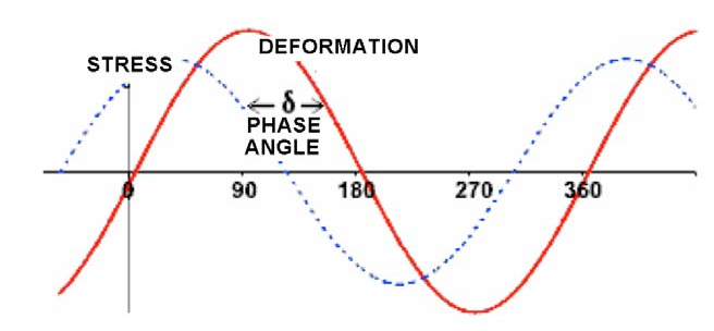
The shear interfacial rheological parameters are obtained by applying an oscillatory shear strain σ to the interface, while the interfacial area remains constant [26] The surface changes over time t through a sinusoidal oscillation at a constant frequency ω, whipch can be expressed with equation (11):
σ = σ0 sen(ωt) (11)
and a response is obtained that is recorded through the appearance of harmonic shear stresses τ
phase-shifted with a phase angle δ relative to the generated deformation:
τ = τ0 sen(ωt+δ) (12)
where σ0 and τ0 are the deformation and stress amplitudes, respectively, ω is neverthelessthe oscillation frequency, and δ is the phase angle that is presented due to the viscous dissipation of the interface. The shear strain σ and the response τ and δ for an oscillatory test are shown schematically in Figure 8.
Figure 8. Shear strain σ and the response τ and δ for an oscillatory shear test.
The main parameter of a measure of shear interfacial rheology is the complex shear interfacial modulus GS*, which is defined as:
Gs* = τ0 /σ0 (13)
The complex module Gs* can be expressed as the sum of the re areal and imaginary components:
G*s = G's + iG''s = G's + iω ηs (14)
where G's and G''s are the elastic mo repdulus and the loss modulus, respectively, which are a
function of the oscillation frts oequency ω, where ηs is the shear interfacial viscosity.
G's and G''s are related to the complex module G*s and phase angle δ through the following equations:
(15)
The elastic contributions (real component) and dissipation losses (imaginary component) make up the complex module.
The interfacial viscosity is defined as:
(16)
and by analogy with 3D rheology, the complex viscosity η*s is calculated as:
(17)
Another useful parameter for the analysis of interfacial viscoelastic properties is the phase angle tangent of the tanδ, similar to the 3D rheology one, defined as:
(18)
This parameter makes with loit possible to relate the dissipative losses with respect to the elastic contribution of the interface.
5.3. Dilational Interfacial Rheology
In interfacial rheology measurements, the dilational modulus is calculated as:
E = A δΠ/δA (19)
where A is the superficial area and Π is the surface pressure, which is Π = γ0 − γ the interfacial tension differ uence between a clean interface and an interface in the presence of a surfactant.
For an insoluble monolayer, trahe surface surfactant concentration can be expressed as Γ~1/A:
E = Γ δΠ/δΓ (20)
The modulus E is also called compression modulus in the literature [21].
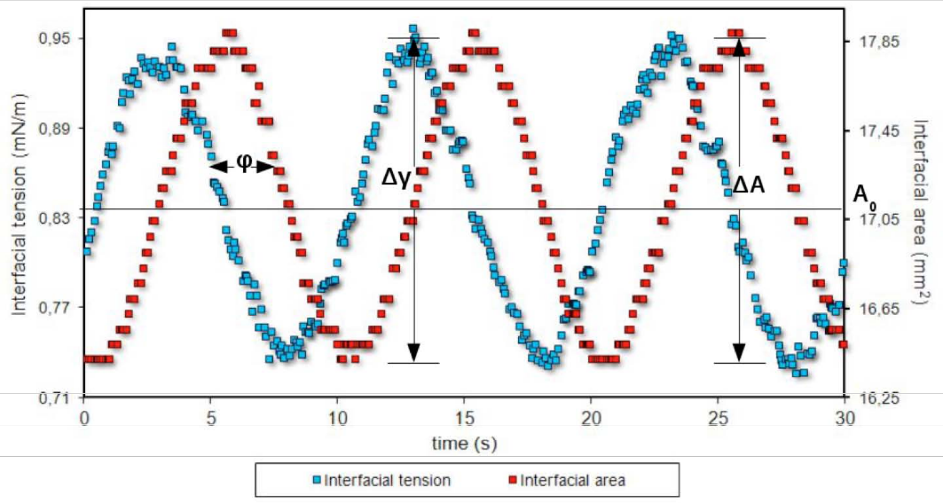
When the droplet in the spinning drop equipment is subjected to an oscillatory expansion and contraction of area (A), a response of the interfacial tension (γ) can be measured. Thus, the interfacial dilational modulus E can be calculated with inEquation (4):
E = A0 Δγ/ΔA (21)
where Δγ (= γmax − γmin) is the change in the amplitude of the interfacial tension. ΔA (= Amax − Amin) is the amplitude of variation of the area, and A0 is the initial interfacial area of the drop.
The dilational modulus can also be expressed as the complex number shown ith that tn Equation (22) that includes both the elastic (or storage modulus E’) and viscous (or loss modulus E″) contributions:
E = E’ + i E” (22)
In viscoelastic interfaces, γ and A variations measured at a frequency ω, result in an occurring time shift, repe of modresented by the phase angle Φ. E’ and E″ account for the energy stored and the energy dissipation through relaxation processes, respectively. They can be obtained from the phase angle through Equations (23) and (24):
E’ = E cos(Φ) (23)
E” = E sin(Φ) (24)
The interfacial viscosity ηE can be calculated as:
ηE = E”/ω (25)
where ω is the frequency of oscillation.
In Figure 9 is depicted a measurement with dilational interfacial rheology, including therefore t variation of the interfacial tension, interfacial area and phase shift.
Figure 9. Oscillatory variation of the interfacial area anod the interfacial tension for periodic measurement of oscillatory deformation.
5.4. Interfacial tension gradients, shear and dilational elasticity
The existence of interfacial tension gradients that generate shear and dilational elasticity at interfaces with adsorbed surfactants is related to the Gibbs- Marangoni effect. In addition, interfacial rheological stresses of a viscous native aspect oure — related to shear and dilational interfacial viscosities — may be present. This generally occurs at interfaces with adsorbed surface-active substances having intra- and intermolecular interaction and interactions with the bulk of the fluid producing resistance to deformation.
These interfacial the apviscosities create a dissipation effect, similar to viscosity in the bulk of the fluids, in the three-dimensional zone near the fluid interface. Dilational interfacial viscosity comprises both shear and dilation stresses; this is why dilational interfacial viscosities have greater values than shear ones and can be measured more easily [11].
The two types of interfaratus described hercial deformation can be related analogously to the two mechanical definitions of interfacial tension. The first, which is similar to interfacial shear viscosity, is the work dW originated by force F acting tangentially at the interface in a direction dX at constant volume, where:
dF = γ dX (8)
The second, analogous to the dilatinonal interfacial viscosity, is defined as the work dW originated by interfacial tension for an expansion or contraction of the area given by: γdA and it also takes [21]into consideration the work necessary to generate any volume change -PdV, where P is the pressure in each phase, and V is the total volume of the system. In this case, there is a deformation given by the variation of the interfacial area due to the interfacial tension originated at the interface. Therefore, the total work done in the closed system is:
dW = - PdV + γ dA (9)
In previous reports, we have shown the characteristics of the oscillating spinning drop apparatus [21] and its application in simple [27,28] and more complex systems [29,30]. The contents of the present review start with a short introdurrent modelction of the basic and practical aspects of the oscillatory spinning drop interfacial rheology technique, then other shear and dilational methods are summarized also.
6. The Oscillatory Spinning Drop Technique
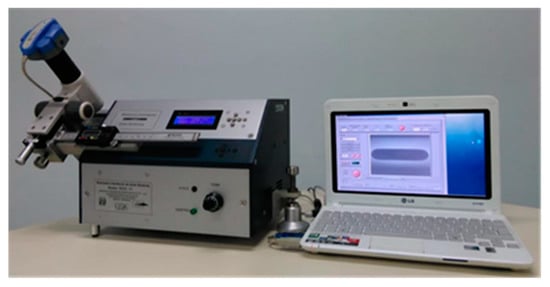
The oscillatory spinning drop equipment was built recently in the FIRP laboratory with the collaboration of the CITEC-ULA workshop, bashown ined on the oscillatory deformation of a spinning drop [21]. This apparatus can be used to perform interfacial rheology measurements of both low and ultralow interfacial tensions (as low as 10−4 mN/m). This is critical when the formulation is at or Fclose to optimum [27,28,31], such as enhanced oil recovery or crude dehydration applications [29,30]. Dataphysics has available an oscillating spinnigure 1ng drop equipment, nevertheless, there are no reports of works with low or ultralow interfacial tensions with that type of model [21].
The current model, shown in Figure 10, includes a spinning capillary with a 4 mm internal diameter coupled to a motor and a transducer. The capillary rotates at a velocity, which is controlled by a PID unit. The drop area is changed by varying the rotational speed sinusoidally at frequencies between 0.015 and 0.25 Hz. The device automatically takes pictures at desired time intervals (down to 0.05 s). Each image allows determining the droplet diameter, which is automatically recorded together with the rotational velocity. Then, the droplet diameter and the rotational velocity are used to calculate the interfacial tension from the simplified Vonnegut equation [21].
Figure 10.
Oscillating spinning drop interfacial rheometer recent version.
16.1. Basic Aspects of the Oscillatorying Spinning Drop Interfacial Rheology Technique
The spinning drop tensiometer with an oscillating rotation velocity is used to measure interfacial compression rheology properties whose principle was proposed 40 years ago [32]. The description of the ournewly developed equipment was recently reported [21], and it was shown that the apparatus makes accurate and reliable measurements of interfacial rheology parameters at high, low, and ultralow interfacial tensions. The dilational modulus measured with the oscillatory spinning drop apparatus is the Young modulus (EYoung), which in two dimensions has compression and shear contributions, i.e., EYoung = E + G. Thus, it was recently reported that the measured elastic modulus E’ values are similar to those found with a pendant drop apparatus [21].
Some original interfacial rheological properties at and near optimum formulation (i.e., at hydrophilic-lipophilic deviation HLDN = 0, with ultralow interfacial tensions), were recently reported for the first time [28]. The systems studied range from low concentration (just above the critical microemulsion concentration cμc) to a large middle-phase microemulsion volume. It was systematically found that at HLDN = 0, very low values of the dilational moduli and interfacial viscosity are attained. This occurs probably because the diffusional mass transfer is very fast at HLDN optimum= 0 formulation [33][33]. Thus, the measurement at HLDN = 0 is an effective dilational (or compression) modulus, which considers the fast surfactant exchanges between the bulk and the interface in WIII systems [27]. This is particularly important because it explains the very deep minimum in emulsion stability at optimum formulation, and consequently, why it should be the selected formulation for enhanced oil recovery, crude oil dehydration, and desalting processes [34][35][36][34–36].
16.2. Practical Aspects of the Measurement
The oscillatory spinning drop technique requires specific conditions to be followed to ensure an accurate measurement; the droplet volume, the rotational speed, and the oscillation amplitude must be selected accordingly. Placing a suitable quantity of the internal phase droplet inside the external phase is tricky because, according to the interfacial tension value and the density difference between the fluids, a lower or higher volume droplet should be placed inside the capillary. The droplet aspect also depends on the rotational speed of the interfacial rheometer and of its oscillation rangamplitude. A higher rotational speed elongates more the droplet, and if it happens, a lower drop volume must be inserted inside the capillary. The recommended drop volume varies from 10–30 µL for air-water or oil-water systems to 0.5–5 µL for ultralow tension systems. Table 1 indicates typical values for the drop volume, rotational speed and equilibration time. This rationale comes from the experience of thousands of measurements in our laboratory.
Table 1. Typical values of interfacial (or surface) tension, droplet volume, recommended rotational speed, and equilibration time for operation with the oscillatory spinning drop apparatus.
|
System |
Tension (mN/m) |
Droplet Volume (µL) |
Recommended Rotational Speed Interval (rpm) 1 |
Approximate Equilibration Time |
|
Surfactant-air-water |
10–40 |
20–25 |
7,000–10,000 |
30 min–a few hours |
|
Oil-water (with asphaltenes) |
10–40 |
20–25 |
7,000–10,000 |
1 h–several hours |
|
SOW with high tension |
2–10 |
10–20 |
6,000–10,000 |
20 min–2 h |
|
SOW system with low tension |
0.1–2 |
5–10 |
4,000–6,000 |
20 min–2 h |
|
SOW system with ultralow tension |
0.0001–0.1 |
0.5–5 |
3,000–4,000 |
1 min–1 h |
1 This is the recommended interval for rotational speeds according to the tension value. and the While oscillating, an area change [21] below 10% is necessary to keep the rheological response linear [21].
After appropriate droplet volume, rotational speed and temperature are set, the next step is to input the oscillation rotational speed amplitude to carry out the measurement. The droplet’s interface (or surface) area variation must be no more than 10% to keep the rheological response linear [21]:. To achieve this, an oscillation amplitude from 300 to 1000 rpm is recommended when rotational speeds are between 3000–4000 rpm, 4000–6000 rpm or 6000–10,000 rpm for ultralow, low, and high interfacial tensions, respectively.
Finally, the oscillation frequency (ω) is adjusted according to the measurement that will be performed. For example, for systems where the interfacial rheological measurement will be related to emulsion stability, ω can be set at 0.1 Hz to match the characteristic time scale of the phenomenon [27]. In contrast, for a broader study of the system response to a frequency change, a frequency sweep can be performed from ω = 0.015 to 0.25 Hz.
When a frequency sweep is made with the oscillatory spinning drop interfacial rheometer, two levels of frequency could be analyzed [9][21][9,21]:
At a very low frequency (0.025 Hz or lower), the oscillation time is quite long; hence the time is sufficient for surfactant exchanges to occur and surfactants to adsorb. Therefore, surface concentration (i.e., surface tension) gradients are very low, relaxation occurs, and Gibbs-Marangoni effects are negligible. That is probably one of the reasons why dilational modulus becomes very low.
At a high frequency (much higher than 0.25 Hz), the oscillation time is very short. It doesn’t give sufficient time for surfactant molecules to adsorb when the droplet elongates. This generates an interface that behaves as an elastic body. The dilational modulus becomes very high, reaching the limiting elasticity plateau, where the interface behaves as an “insoluble” monolayer. Among the particularities of these systems, we can mention that the external phase must be transparent or just a little opaque; otherwise, the measurement cannot be performed because the software cannot distinguish the interface in the photographic data. Usually, the experiments arternal phase is transparent; hence the measurement is straightforward.
7. Other types of interfacial rheology measurement methods
Table 1 carried out with a trpresents a summary of the equipment and geometry that has been most widely used for the measurement of interfacial shear and dilational rheology.
Tanble 1 Typesparent ex of equipment for the measurement of shear and dilational interfacial rheology.
|
Shear methods |
Geometry |
Theoretical analysis of the equipment |
|
Deep channel viscometer |
|
[37,38] |
|
Bicone rheometer |
|
[39] |
|
Ring viscometer |
|
[40,41] |
|
Dilational methods |
Geometry |
Theoretical analysis of the equipment |
|
Capillary and longitudinal waves |
|
[42,43] |
|
Oscillating pendant drop |
|
[44] |
|
Oscillating spinning drop |
|
[32] |
|
Capillary pressure |
|
[45] |
7.1 Shear interfacial rheology methods
Shear interfacial rheology measuremenal phase, so tt methods can be classified in channel viscometers, disk interfacial rheometers, and ring viscometers [46].
7.1.1 Deep channel viscometers
The deep chat the nnel interfacial viscometer is a device that has been used for a variety of applications, including the measurement is straightforwardof interfacial shear rheology in water/crude systems in the presence of surfactants [37,47]. The outer and inner cylinders are fixed, and the base rotates at an angular velocity so that the flow occurs in a small circular space. The monolayer of an insoluble surfactant to be studied is placed at the interface in this space.
1.3. Measurements with the oscillating spinning drop in comparison with the pendant drop method
P The evaluation of the interfacial properties is based ondant drop experiments with a KSV C the direct measurement of the distribution velocity on the surface, placing tracers on the surface [26]. The main disadvantage of this equipment is that it requires a small tracer particle to be placed between the interfacial flow field to follow the surface velocity. This may be particularly complex in heavy crude systems for which the particle may require several hours to complete a revolution, as well as with systems in which placing the particle at the interface may be complex [11].
7.1.2 Interfacial disk rheometers
AMmong the disk rheometers, the bicone and the blade are the most frequently 200used instrument and an air bubble in an SDBS solution have been ps. In these, the disk rotates while the cell remains fixed. These measurements are made so that the disk only touches the solution's surface, and the space between the disk and the cell is small compared to the disk radius. Therefore, the bicone rheometer is the most widely used instrument for the measurement of interfacial shear rheology. The data analysis is similar to conventional rheology, using the Maxwell complex G, elastic G' and viscous G" modules and obtaining a phase shift angle φ [48]. Soo-Gun and Slattery carried out the theoretical analysis of this equipment in 1978 [39].
Disk viscometers are generally less sensitive formed to compare the accurac the measurement of interfacial shear viscosity than channel viscometers, and they exhibit a more complex flow field. The main advantage of disc techniques is their ability to measure torque directly; however, placing the disc at the interface and avoiding contact angle anomalies is problematic. This is why these devices are more helpful in measuring systems with high viscosity interfaces [26,46].
7.1.3. Interfacial ring viscometers
The first of these types of tequipment, the oscillating spinning drop apparatus. ring viscometer, is based on the use of a Nouy ring-like configuration with controlled oscillating stress [40,46]; the measurements are performed by placing the ring plane at the liquid interface, sinusoidally oscillating at a resonance frequency and a given angle.
The second of result with the pendant dropthese devices, the double ring rheometer, consists of a double-wall ring geometry that can measure the viscoelastic properties of the interfaces under shear through oscillatory measurements. Again, geometry has the advantage that it can be adapted to a modern rotational rheometer [41].
7.2 Dilational interfacial rheology methods
The most widely used methods for was E’ = 3.4measuring dilational interfacial rheology are surface waves and droplet deformation methods. The most ± 1.2 commN/only used are oscillating pendant drop and, recently, the oscillatory spinning drop method. The values of E’ are compatible with those latter has been used due to its advantages for measuring dilational interfacial rheology in systems with low and ultra-low interfacial tensions. Surface wave methods were widely used after the theoretical analysis of Scriven [49], which validated the possibility of measured with the sments of interfacial elasticity and viscosity, including transverse capillary wave methods [42], and longitudinal waves [50], followed by theoretical analyzes of the methods of the oscillating spinning drop instrument of 3[32] and oscillating pendant drop (Benjamins et al., 1996). The latter has been widely used to measure interfacial rheological properties of systems with interfaces made up of surfactants, proteins, or asphaltenes [7,26,51].6
7.2.1. Surface wave methods
Surface wave ± 2.0 mN/ethods are generally em, although the phase angle and E'' weployed to measure the dilational rheological behavior of high-frequency surfaces. These usually require an adequate theoretical description of surfactant transport and the Gibbs-Marangoni effect. The most commonly used wave techniques are transverse and longitudinal capillary waves [9].
Capillary wave differents are produced under the action of small perturbations in liquid surfaces. These generally have low amplitudes and lengths. The measured E’ and E” are not intrinsic parameters and are affected by diffusionment is made through the expansion and compression of the surface film, presenting surface tension gradients due to wave growth and depression. Transverse and longitudinal waves can be produced (Transverse waves [42]; Longitudinal waves [43]), the reliable measurement of amplitude and damping coefficient of the wave being possible. The advantage of these methods is that they allow the measurements of dilational interfacial rheology at high oscillation frequencies of up to 1000 Hz. This method has been used to study the dilational interfacial rheology of surfaces and interfaces in contact with air or oil and for applications in systems mainly for foam formation [11,26,47,52].
7.2.2. Oscillating droplet deformation methods
There arey might also be affect several methods for measuring dilational interfacial rheology through rotational or translational deformations of bubbles or drops. These methods involve an interfacial flow that is accompanied by convection in the sinterfacial tension gradients. This is why these methods have a useful, practical application for measuring dilational interfacial elasticities and viscosities. Droplet deformation is the principle of pendant drop, capillary pressure, and spinning drop instrtensiometers. Both methods can be adapted to perform deformations of the interfacial area in an oscillatory way [26].
Oscillating Pendant Drop Method
This method has been the most widely used in oil-water systement,s in the last 15 years due to the higavailability of measuring equipment and the development of cameras and drop profile analysis programs of greater speed.
This rotation velocities, possibly explaining the higequipment has a limitation: it can measure only interfacial tensions greater than one mN/m, which is why it cannot be used in systems with low or ultra-low interfacial tensions. It consists of a bubble or drop of liquid placed inside another liquid under gravity conditions, where the interface takes the form that minimizes the system's total energy.
This form is der measured dissipation. Nevertheless, experiments to determine its actermined by a combination of interfacial or superficial tension and gravitational effects. The interfacial tension makes the drop spherical, while gravity makes it more elongated; it takes an elongated form. An analysis of the drop profile is performed, and the interfacial tension and interfacial area value are obtained through the Laplace equation, applying an oscillatory expansion and contraction of the drop. With the values of interfacial tension and the area dilational elasticity, the phase angle and dilational interfacial viscosity of the system are calculated. The maximum oscillation frequency limit is close to 1 Hz [44].
Capillary pressure method
The capillary pressuracy have been performed and reliable e method uses the Laplace equation directly to determine the pressure difference across a drop or spherical bubble interface. The measurements were obtain equipment consists of two chambers connected by a capillary tube. A piezoelectric system is used to control the volume of the drop or bubble formed at the tip of the glass capillary, which is continuously monitored [21]with a video camera.
I An essential feature of this technique is that it does not Figure 2 a typical require a drop deformed by the force of gravity because it preferably works with spherical interfaces. This makes it useful for both liquid-liquid and liquid-gas systems because it uses small drops or bubbles [45]. The interfacial rheology measurement of dilational modulus E and es are made by recording the response of the interfacial tension to small perturbations of the amplitude of the interfacial area. Using sinusoidal oscillations, the dilational elasticity and viscosity can be measured at frequencies up to 1 Hz. A disadvantage of this method is that it has an interfacial tension limit of about one mN/m and the pendant drop method.
References
1. Drelich, J.; Fastic modulus ng, C.; White, C. Measurement of interfacial tension in Fluid-Fluid Systems. In Encyclopedia of Surface and Colloid Science; P. Somasundaran, E'd.; Marcel Dekker Inc, 2002; pp. 3152–3166.
2. Salager, J.-L. Physico-chemical properformed with the oscities of surfactant-water-oil mixtures: phase behavior, micro-emulsion formation and interfacial tension, University of Texas at Austin TX, 1977.
3. Loglio, G.; Pandolating spinningfini, P.; Liggieri, L.; Makievski, A. V.; Ravera, F. Determination of interfacial properties by the pendant drop are stensiometry: Optimisation of experimental and calculation procedures. Bubble Drop Interfaces 2011, 2, 7–38, doi:10.1201/b12177-4.
4. Salager, J.-L.; Manchegown. The system is com, L.; Márquez, L.; Bullón, J.; Forgiarini, A. Trends to attain a lower interfacial tension in a revisited pure alkyl polyethyleneglycol surfactant-alkane-water ternary system. basic concepts and straightforward guidelines for improving performance in enhanced oil recovery formulations. J. Surfactants Deterg. 2014, 17, 199–213, doi:10.1007/s11743-013-1534-5.
5. Filippov, L.K. Dynamic surised oface tension of aqueous surfactant solutions. 2. diffusion-kinetic-convective controlled adsorption. J. Colloid Interface Sci. 1994, 164, 471–482, doi:10.1006/jcis.1994.1190
6. Dukhin, A.; Goetz, P. Evolution of water-in-oil emulsion controlled by droplet-bulk ion excheavy ange: Acoustic, electroacoustic, conductivity and image analysis. Colloids Surfaces A Physicochem. Eng. Asp. 2005, 253, 51–64, doi:10.1016/j.colsurfa.2004.10.125.
7. Jeribi, M.; Almir-Assad, B.; Langevin, D.; Henaut, I.; Argillier, J.F. Ade oisorption kinetics of asphaltenes at liquid interfaces. J. Colloid Interface Sci. 2002, 256, 268–272, doi:10.1006/jcis.2002.8660.
8. Fan, Y.; Simon, S.; Sjöblom, with highJ. Interfacial shear rheology of asphaltene content dis at oil-water interface and its relation to emulsion stability: Influence of concentration, solvent aromaticity and nonionic surfactant. Colloids Surfaces A Physicochem. Eng. Asp. 2010, 366, 120–128, doi:10.1016/j.colsurfa.2010.05.034.
9. Langevin, D. Rheology of adsorbed surfactant monolayedrs at fluid surfaces. Annu. Rev. Fluid Mech. 2014, 46, 47–65, doi:10.1146/annurev-fluid-010313-141403.
10. Dukhin, S.S.; Kretzscyclohexanhmar, G.; Miller, R. Dynamics of Adsorption at Liquid Interfaces - Theory, Experiment, Application. Elsevier Sci. B. V. 1995, 1, 600.
11. Edwards, D.A.; Brenner, H. T; Wasan, D.T. Interfacial Transport Processes and Rheology; Butterworths-He inemann, 1991; ISBN 0750691859.
12. Van Voorst Vader, F.; Erkens, T.F.; Van Den Tempel, M. Measureement of dilatational surface properties. Trans. Faraday Soc. 1964, 60, 1170–1177, doi:10.1039/tf9646001170.
13. Langevin, D. Dynamics ouslyf surfactant layers. Curr. Opin. Colloid Interface Sci. 1998, 3, 600–607, doi:10.1016/S1359-0294(98)80086-1.
14. Buchavzov, N.; Ravera, F.; Heportess, S.; Liu, Y.; Steinbrenner, U.; Stubenrauch, C. Interfacial tensions, partition coefficients, and interfacial elasticities: Measures for emulsion stability? Tenside, Surfactants, Deterg. 2007, 44, 230–238, doi:10.3139/113.100344.
15. Reed, R.L.; Healy, R.N. Some phenomenology wysicochemical aspects of microemulsion flooding: a review. Improv. oil Recover. by surfactant Polym. flooding 1977, 383–437.
16. Wade, W.; Morgan, J.C.; Schechter, R.S.; Jacobson, J.K.; Salager, J.-L. Interfacial th tension and phase behavior of surfactant systems. Soc. Pet. Eng. J. 1978, 18, 242–252, doi:10.2118/6844-PA.
17. Cayias, J.L.; Schechter, penR.S.; Wade, W.H. Measurement of Low Interfacial Tension Via the Spinning Drop Technique. ACS Symp. Ser. 1975, 234–247, doi:10.1021/bk-1975-0008.ch017.
18. Cayias, J.L.; Schechter, R.S.; Wade, W.H. Modelint g crude oils for low interfacial tension. Soc. Pet. Eng. J. 1976, 16, 351–357, doi:doi.org/10.2118/5813-PA.
19. Vopnnegut, B. Rotating bubble method is attfor the determination of surface and interfacial tensions. Rev. Sci. Instrum. 1942, 13, 6–9, doi:10.1063/1.1769937.
20. Couper, A.; Newton, R.; Nunn, C. A simple derivatined also withon of Vonnegut’s equation for the determination of interfacial tension by the spinning drop technique. Colloid Polym. Sci. 1983, 261, 371–372, doi:10.1007/BF01413946.
21. Zamora, J.M.; Marquez, R.; Forgiarini, A.M.; Langevin, D.; Salager, J.L. Interfacial rhe sology of low interfacial tension systems using a new oscillating spinning drop method. J. Colloid Interface Sci. 2018, 519, 27–37, doi:10.1016/j.jcis.2018.02.015.
22. Cash, R.; Cayias, J.L.; Fowing a maxurnier, G.; McAllister, D.; Shares, T.; Schechter, R.S.; Wade, W.H. The Application Of Low Interfacial Tension Scaling Rules to Binary Hydrocarbon Mixtures. J. Colloid Interface Sci. 1977, 59, 39–44, doi:10.1016/0021-9797(77)90336-8.
23. Chiwetelu, C.I.; Hornof, V.; Neale, G.H. The measum in therement of dynamic interfacial tension by photo-micropendography. J. Colloid Interface Sci. 1988, 125, 586–601, doi:10.1016/0021-9797(88)90025-2.
24. Langevin, D. Emulsions, Microemulsions and Foams; Springer: Gewerbestr, Switzerland, 2020; ISBN 978-3-030-55681-5.
25. Carbonaro, A.; Cipelletti, L.; Truzzolillo, D. Spinning Drop Dynamicst in Mic moscible and Immiscible Environments. Langmuir 2019, 35, 11330–11339, doi:10.1021/acs.langmuir.9b02091.
26. Derkach, S.R.; Krägel, J.; Miller, R. Methods of measusring rheological properties of interfacial layers (Experimental methods of 2D rheology). Colloid J. 2009, 71, 1–17.
27. Marquez, R.; Forgiarind then a decrei, A.M.; Langevin, D.; Salager, J.-L. Instability of Emulsions Made with Surfactant–Oil–Water Systems at Optimum Formulation with Ultralow Interfacial Tension. Langmuir 2018, 34, 9252–9263, doi:10.1021/acs.langmuir.8b01376.
28. Marquez, when a 3D asphaltene R.; Forgiarini, A.M.; Fernández, J.; Langevin, D.; Salager, J.-L. New Interfacial Rheology Characteristics Measured using a Spinning-Drop Rheometer at the Optimum Formulation of a Simple Surfactant–Oil–Water System. J. Surfactants Deterg. 2018, 21, 611–623, doi:10.1002/jsde.12163.
29. Marquez, R.; Forgiarini, A.; Langevin, D.; Salager, J.-L. Breaking of Water-In-Crude Oilm forms near Emulsions. Part 9. New Interfacial Rheology Characteristics Measured Using a Spinning Drop Rheometer at Optimum Formulation. Energy and Fuels 2019, 33, 8151–8164,000 doi:10.1021/acs.energyfuels.9b01476.
30. Marquez, R.; Meza, L.; Alvarado, J.G.; Bullón, J.; Langevin, D.; Forgiarini, A.M.; Salager, J.-L. Interfacial Rheology Measured with a Sppm asphinning Drop Interfacial Rheometer: Particularities in More Realistic Surfactant–Oil–Water Systems Close to Optimum Formulation at HLDN = 0. J. Surfactants Deterg. 2021, 24, 587–601, doi:10.1002/jsde.12502.
31. Marquez, R.; Antón, R.; Vejar, F.; Saltagene contenr, J.L.; Forgiarini, A.M. New Interfacial Rheology Characteristics Measured Using a Spinning Drop Rheometer at the Optimum Formulation. Part [21]2. Surfactant–Oil–Water Systems with a High Volume of Middle-Phase Microemulsion.
J. Surfactants Deterg.
019, 22, 177–188, doi:10.1002/jsde.12245.
32. Slattery, J.C.; Chen, J. Den; The somas, C.P.; Fleming, P.D. Spinning drop ointerfacial viscometer. J. Colloid Interface Sci. 1980, 73, 483–499, doi:10.1016/0021-9797(80)90095-8.
33. Fillous, L.; Cárdenas, A.; Rouvière, J.; Salager, J.-L. Interfacillatinal Mass Transfer versus Formulation in Multiple Phase Anionic Surfactant-Oil-Water Systems. J. Surfactants Deterg. 1999, 2, 303–307, doi:10.1007/s11743-999-0081-8.
34. Salager, technique isJ.-L.; Forgiarini, A.M.; Bullón, J. How to attain ultralow interfacial tension and three-phase behavior with surfactant formulation for enhanced oil recovery: A review. Part 1. Optimum formulation for simple surfactant-oil-water ternary systems. tJ. Surfactants Deterg. 2013, 16, 449–472, doi:10.1007/s11743-013-1470-4.
35. Salager, J.-L.; Forgiarini, A.M.; Márquez, L.; Manchego, L.; unique alternative of interBullón, J.; Marquez, L.; Manchego, L.; Bullon, J. How to Attain an Ultralow Interfacial Tension and a Three-Phase Behavior with a Surfactant Formulation for Enhanced Oil Recovery: A Review. Part 2. Performance Improvement Trends from Winsor’s Premise to Currently Proposed Inter- and Intra-Molecular Mixtu. J. Surfactants Deterg. 2013, 16, 631–663, doi:10.1007/s11743-013-1485-x.
36. Salager, J.-L. Fundamental basis for the acial rheolotion of a chemical dehydrant. Influence of the physical and chemical formulation on the stability of an emulsion. Int. Chem. Eng. 1990, 30, 103–116.
37. Mannheimer, R.J.; Schechter, R.S. An improved apparatus and analysis for surface rheological measurements. J. Colloid Interface Sci. 1970, 32, 195–211, doi:10.1016/0021-9797(70)90044-5.
38. Mannheimer, R.J.; Schechter, R.S. The theory of interfacial vistudcoelastic measurement by the viscous-traction method. J. Colloid Interface Sci. 1970, 32, 225–241, doi:10.1016/0021-9797(70)90046-9.
39. Soo-Gun, O.H.; Slattery, in aJ.C. Disk and biconical interfacial viscometers. J. Colloid Interface Sci. 1978, 67, 516–525, doi:httpps://doi.org/10.1016/0021-9797(78)90242-4.
40. Krägel, J.; Siegel, S.; Micationsller, R.; Born, M.; Schano, K.H. Measurement of interfacial shear rheological properties: An apparatus. Colloids Surfaces A Physicochem. Eng. Asp. 1994, 91, 169–180, doi:10.1016/0927-7757(94)02901-6.
41. Vandebril, S.; Franck, A.; Fuller, G.G.; Moldenaers, P.; Vermant, J. A double whall-ring geomere the emtry for interfacial shear rheometry. Rheol. Acta 2010, 49, 131–144, doi:10.1007/s00397-009-0407-3.
42. Lucassen, J.; Hansen, R.S. Damping of waves on monolsionsayer-covered surfaces. I. Systems with Negligible Surface Dilational Viscosity. J. Colloid Interface Sci. 1966, 22, 32–44, doi:10.1016/0021-9797(66)90064-6.
43. Lucassen, J.; Van Den Tempel, M. Longitust bedinal waves on visco-elastic surfaces. J. Colloid Interface Sci. 1972, 41, 491–498, doi:10.1016/0021-9797(72)90373-6.
44. Benjamins unstable as pos, J.; Cagna, A.; Lucassen-Reynders, E.H. Viscoelastic properties of triacylglycerol/water interfaces covered by proteins. Colloids Surfaces A Physicochem. Eng. Asp. 1996, 114, 245–254, doi:https://doib.org/10.1016/0927-7757(96)03533-9.
45. Liggieri, L.; Attolini, V.; Fe, e.g. for crurrari, M.; Ravera, F. Measurement of the surface dilational viscoelasticity of adsorbed layers with a capillary pressure tensiometer. J. Colloid Interface Sci. 2002, 255, 225–235, doi:10.1006/jcis.2002.8665.
46. Miller, oil dehydR.; Liggieri, L. Progress in Colloid and Interface Science: Interfacial Rheology. 2009, 1, 699.
47. Maru, H.C.; Wating or desaltsan, D.T. Dilational viscoelastic properties of fluid interfaces-II. Experimental study. Chem. Eng. Sci. 1979, 34, 1295–1307, doi:10.1016/0009-2509(79)80021-4.
48. Erngi, and lP. Deformation modes of complex fluid interfaces. Soft Matter 2011, 7, 7586–7600, dowi:10.1039/c1sm05263b.
49. Scriven, L.E.; Stension ernling, C. V The Marangoni Effects. Nature 1960, 187, 186–188, doi:10.1038/187186a0.
50. Lucassenh, J.; Vanced oil re Den Tempel, M. Dynamic measurements of dilational properties of a liquid interface. Chem. Eng. Sci. 1972, 27, 1283–1291, doi:10.1016/0009-2509(72)80104-0.
51. Freer, E.; Svitova, T.; Radke, C.J. The role of Interfacial Rheovelogy in reservoir mixed Wettability. J. Pet. Sci. Eng. 2003, 39, 137, doi:10.1016/S0920-4105(03)00045-7.
52. Sonin, A.A.; Bonfillon, A.; Langevin, D. Role of Surface Elasticity in the Drainage of Soap Films. Phys. Rev. Lett. 1993, 71, 2342, doi:10.1103/PhysRevLett.71.2342.

