In the current context of transition from the powertrains of cars equipped with internal combustion engines to powertrains based on electricity, there is a need to intensify studies and research related to the command-and-control systems of electric vehicles. One of the important systems in the construction of an electric vehicle is the thermal management system of the battery with the role of optimizing the operation of the battery in terms of performance and life.
- battery
- thermal management
- design
- performance
- heath transfer
- efficiency
1. Introduction
23. Battery Thermal Management Systems
2.1. Air-Based BTMS
3.1. Air-Based BTMS
The advantages of these systems are the low cost, simplicity, light extra weight [33][34][56,57], and despite their low-conductivity and low-efficiency [35][58], they are still studied by researchers and used in electric-driven vehicles. A first classification of air-based systems can be made considering whether it is natural or forced convection. Despite its simple structure, the natural method creates large thermal gradients in the battery pack and is highly dependent on ambient conditions [36][59]. Therefore, a forced-air system is necessary for most applications, despite its higher costs and additional power consumption. A second classification of air-based systems is based on the source of the air, which can be external, cabin pre-conditioned or pre-conditioned by an auxiliary heat exchanger [6].2.2. Liquid-Based BTMS
3.2. Liquid-Based BTMS
Liquid-cooled systems are the most used in practical applications [37][39], due to their high efficiency and compactness. Liquid possesses good heat capacity and heat transfer coefficient, representing a suitable solution for the BTM of EVs [38][68]. Compared to an air-cooling system, 2–3 times less energy is needed to maintain the same average temperature of the batteries [39][69]. The disadvantages are the increased complexity, added weight, extra costs, rigidity of the structure [40][41][55,70]. Moreover, a significant additional power is required to circulate the fluid at the desired flow rate, increasing the overall energy consumption of the vehicle [42][71]. Liquid-cooling is easily applicable for prismatic batteries due their regular shape, allowing a compact arrangement of the BTMS, while cylindrical batteries require special structures to integrate the cooling channels, increasing the system’s complexity and mass. The most common solution for prismatic and pouch batteries is the implementation of cooling plates. General investigations analyze the temperature and velocity distribution inside the cooling plates [43][72], and several studies [44][45][46][73,74,75] investigate by means of orthogonal test the influence of different parameters, such as liquid inlet temperature, cooling plate width, mass flow rate or number of channels. Shang et al. [44][73] obtained an improvement of 12.61% compared to the maximum temperature without the orthogonal optimization. Ye et al. [45][74] achieved a lowering of maximum temperature by 5.24% and of the pressure drop by 16.88%. The sensitivity analysis of the orthogonal test also showed that the greatest influence on the pressure loss is caused by the center channel distance and the size of the inlet plenum. The numerical calculations conducted by Monika et al. [46][75] showed that for cold plates placed between the batteries, a parallel flow arrangement with the inlet placed near the tab region represents the best solution. The authors found that a 5-channeled cold plate of 4 mm width represents the best trade-off between heat transfer and pressure drop. Patil et al. [47][76] conducted a parametric study to evaluate the thermal performance of different U-turn type microchannel cold plates. The results suggest that a surface area coverage ratio of 0.75 and a hydraulic diameter of the channels of 1.54 mm offer the best cooling capacity. The numerical simulations also show that alternating single inlet and outlet channels decrease the maximum temperature and improve temperature uniformity.2.3. PCM-Based BTMS
3.3. PCM-Based BTMS
Phase change materials represent an interesting alternative to the conventional forced-air and liquid cooling systems, because it could allow the implementation of a passive BTMS. It is applied especially for cylindrical batteries, because it allows the filling of the unused spaces between the batteries. PCMs have high latent heat capacity and are able to maintain the temperature of the batteries in a small range, close to the melting temperature of the PCM [48][89]. The melting point is in the 5.5–76 °C temperature range and the phase change process is usually not isotherm [9]. In case of continuous charge and discharge cycles at high rates, there is the risk of the PCM melting completely, leading to thermal instability and leakage of the PCM. Moreover, the melting of the PCM automatically increases its volume, which must be considered when designing a PCM-based BTMS. Another disadvantage of PCMs is their low thermal conductivity, resulting in a difficult heat dissipation. Numerous studies addressed the problem of low thermal conductivity. Azizi et al. [49][90] constructed a BTMS made of PCM and aluminum wire mesh plates as a thermal conductivity enhancer. The wire mesh plates with high voidage values are preferred over the aluminum foams for a better filling of the pores during the phase change of the PCM. Zhang et al. [50][91] study the influence of different concentrations of aluminum nitrite (AlN)-based CPCMs. The measurements showed that increasing the AlN mass fraction improved thermal conductivity from 1.48 W/mK to 4.331 W/mK at 50 °C, as well as the tensile strength, bending strength and impact strength. Zhang et al. [51][92] designed and experimentally investigated a BTMS using copper metal foam saturated PCM. For a 5 C discharge rate the maximum temperature was lowered to 47.86 °C compared to 54.115 °C in the case of pure PCM. The temperature non-uniformity increasing rate also showed smaller values.2.4. Heat Pipe-Based BTMS
3.4. Heat Pipe-Based BTMS
Heat pipes are heat transfer devices with extremely high thermal conductivity, 90 times higher than copper [52][111], ensuring better heat dissipation and temperature uniformity. They represent a passive, compact, lightweight BTMS, with no need of maintenance and long life cycle [53][112]. The working principle consists in the phase change of the internal working fluid, which absorbs heat at the evaporation section and releases it at the condensation section. As long as there is a temperature gradient between the two sections, the transfer of heat goes on, without any power consumption. Despite its very high thermal conductivity however, in most applications heat pipe is coupled with forced air or liquid cooling for a more effective heat dissipation at the condensation section. Heat pipe-based BTMSs are studied mostly for prismatic and pouch batteries due to the adaptability of the shapes and the large available contact areas, while in case of cylindrical batteries special attention needs to addressed to the contact surface between heat pipe and batteries. Zhang et al. [54][113] proposed a passive heat pipe-based BTMS for prismatic batteries, using flat heat pipes with fins, as presented in Figure 11a. Compared to natural convection and aluminum plates, the maximum temperature was 73.7% lower and the maximum temperature difference 50.1% lower. Behi et al. [53][112] designed a smart heat pipe-based BTMS, using the least number of heat pipes based on the multizone analysis of temperature distribution determined by thermal imaging. The high discharge investigation revealed that the most critical zone of a prismatic LTO cell is the center top region. The thermal analysis, illustrated in Figure 11c, showed that a single heat pipe with an optimal placement is sufficient. Kleiner et al. [55][114] introduced a concept where heat pipes are attached to the terminals of prismatic batteries, as presented in Figure 11b. This reduces the heat flow path and thermal resistance from the heat generation sources, located in the busbar and inside the battery, to the cooling system at the bottom of prismatic batteries. The results show that without any increase in charging time, temperature at the terminals and in the jelly roll are 19 °C, respectively 2 °C lower. Temperature distribution is also improved, due to conduction of 27% of the generated heat.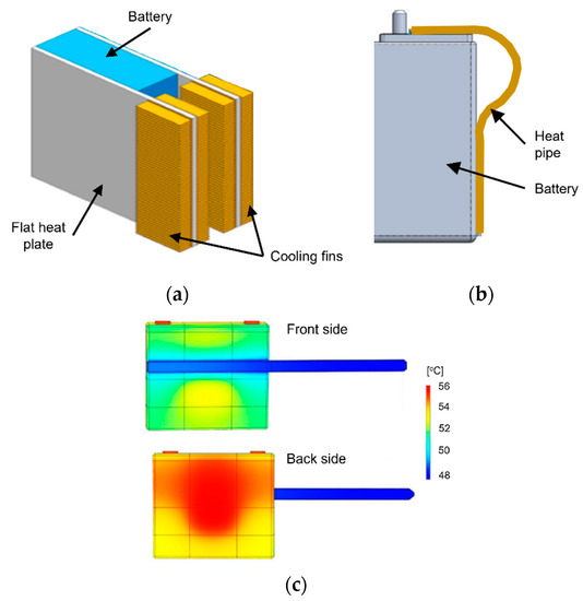
2.5. Hybrid BTMS
3.5. Hybrid BTMS
34. Conclusions
Air cooling represents the most easily applicable solution for the thermal management of batteries. However, the low specific heat of air still is a major concern when considering its application in full-size battery packs. A possible solution could be the use of active cooling and heating, using an evaporator or heater core. This would allow a reduced dependency on ambient conditions, an increased control over the inlet temperature in the battery pack and therefore a more efficient management of the temperatures inside the pack. Although such a method would increase the heat transfer, the occupied large volume still represents a significant disadvantage. The inlet and outlet scheme and the air flow configuration are also promising research directions, with numerous possible combinations. However, the possibility of implementing these schemes in a full-size battery pack should also be investigated, considering the need to implement the required inlet and outlet channels in the tight package of a vehicle. Regarding the uneven temperature distribution of air cooling, this can be reduced by using air flow channels with variable widths or by distribution pipes.
The large use of prismatic and pouch batteries in commercial vehicles means that liquid cooling plates are one of the most implemented cooling systems in electric vehicles, due to their good heat capacity and compact arrangement. Most research studies focus on various parameters regarding heat transfer and pressure drop, but only a few consider the uneven heat generation in the batteries, which is even more significant for the larger prismatic and pouch batteries. Therefore, more attention in future studies should be accorded to the possibility of implementing bidirectional or reciprocating liquid flows, considering the local heat generation, therefore improving the temperature distribution. In the presented study, examples of improving the temperature uniformity offered by cooling plates are presented using double-layered plates and a better mass distribution in the channels. The heat transfer capacity of conventional liquid cooling systems can further be enhanced using PCM emulsions or liquid metal. For cylindrical batteries, the poor adaptability to indirect liquid cooling is represented by the use of wavy channels, half helical ducts or conduction elements, which significantly increase complexity and add weight to the system.
Adapting the existing refrigerant circuit of the vehicles to serve also for the thermal management of batteries is a concept with a relatively high probability of practical application. The presented studies clearly show the potential of such systems, having a high heat transfer capacity, a capability to cool below ambient temperature and the possibility of heating. Despite these advantages, there are no mentioned studies to analyze the sizing of such a system for a full-size battery pack, nor the necessary changes to the existing air conditioning system to cope with the additional thermal load of the battery. More effort should be directed towards the development of a large-scale system, with precise control algorithms for cabin comfort, battery maximum temperature and temperature uniformity.
The main disadvantages of pure PCMs, namely the low thermal conductivity and leakage problems can be tackled by adding other materials such as EG, AlN, nanosilica, copper mesh foam and others, to form CPCMs. Although the enhancement of pure PCM with additional materials in different concentrations is a promising research direction, the preparation processes are very laborious, as well as time and energy consuming. It could be of interest by how much the preparation of large quantities of CPCM increases the overall costs of full-size battery packs. Moreover, in the case of pouring hot, melted CPCM directly around the batteries, further investigations are needed regarding the possible negative effects on Li-ion batteries.