Integral bridges are a class of bridges with integral or semi-integral abutments, designed without expansion joints in the bridge deck of the superstructure. The significance of an integral bridge design is that it avoids durability and recurring maintenance issues with bridge joints, and maybe bearings, which are prevalent in traditional bridges. Integral bridges are less costly to construct.
- integral bridge
- integral abutment bridge (IAB)
- semi-integral abutment bridge (SIAB)
- cyclic temperature loading
- stress ratchetting
- settlement bump
- earth pressure distribution
- soil–structure interactions (SSI)
1. Introduction
Traditionally, bridges are designed and constructed with expansion joints and bearings to accommodate the expansion and contraction of the bridge due to temperature and stress changes. However, expansion joints and bearings need regular maintenance and replacement due to cyclical deck movement, traffic loading, trapped debris, and salt and moisture intrusion [1][2][1,2]. Degradation of expansion joints is a persistent cause of costly maintenance and rectification work [3]. Failure to maintain the bridge joints and bearings could cause overstress and structural distress in the bridge structure, which must be avoided. Rectification work is often disruptive to traffic flow and causes an increase in travel time that also incurs socio-economic costs for road users. Although conventional or jointed bridges still outnumber integral bridges, the overall trend of bridge construction towards integral bridges is increasing to avoid the recurring maintenance issues related to bridge joints and bearings.
Integral bridges have been used since 1938 in Ohio, the United States of America (USA) [4]. During the construction boom of the National Interstate Highway System, in the late 1950s and mid-1960s, several USA states began to use integral bridges as a construction choice for bridges. In 1980, the American Federal Highway Association (FHWA) recommended bridges to be constructed as integral bridges for steel bridges with overall lengths up to 90 m, cast-in-place concrete bridges up to 150 m and post-tensioned bridges up to 183 m [5]. According to Tabatabai et al. [6], approximately 70% of the USA State Department of Transportation (DOT) have already included integral bridges in their jurisdictions. In 1996, the British Highway Agency recommended adopting an integral bridge design approach for any bridge with a length of up to 60 m [7]. Integral bridges in other regions and countries, e.g., Europe, Japan, Canada, China and Oceania, also witnessed rapid development in the last few decades.
Under cyclic thermal, environmental and mechanical loading, the bridge superstructure expands and contracts. Movements particularly in the bridge deck of integral bridges will cause the bridge abutment to displace directionally into and away from the approach fill with each cycle. The movements of the abutment and substructure mobilise significant soil–structure interaction (SSI) effects [8][9][10][11][8,9,10,11], such as stress variations, soil densification, stress ratcheting [12][13][14][12,13,14], heave, settlement and/or slumping of the backfill soil [15][16][15,16], which in turn affect the overall performance of integral bridges. Stress ratcheting is the phenomenon that increases the lateral earth pressure applied on the abutments due to cyclic movements transferred from the bridge deck [12]. Pile-supported systems will also be affected by the abovementioned issues of integral bridge. The repeated actions of deck movements, much of which is induced by temperature changes, may be transferred to the piles, changing the soil properties around the pile. Many researchers have reported that the overall pile–soil interaction is dependent on various factors including pile type, pile orientation, pile flexibility, soil properties around piles and substructure stiffness [17][18][19][20][17,18,19,20]. Cyclic displacements and moments transferred to pile foundations are at risk of causing pile fatigue failure [21]. The complexities associated with pile–soil interaction ultimately affect the overall performance of the integral bridge including the bridge approach. Despite this, Philip [22] reported that only two states in the USA consider the pile stress due to thermal movements, while other states neglect this aspect in the integral bridge design.
It is quite evident from literature that different countries and jurisdictions are using a variety of design guidelines and practices to deal with the geotechnical issues for abutments and pile foundations. Therefore, this paper aims to present a comprehensive review of the design guidelines and the literature relevant to the recommended practices corresponding to the geotechnical aspects of integral bridges incorporating the effects of SSI. In the literature, a variety of definitions and terminologies have also been used to describe integral bridges. This can sometimes cause confusion to the reader. Hence, this paper begins with a discussion on different terminologies and definitions used for integral bridges to establish the context for the review.
2. Terminologies and Definitions of Integral Bridges
The diversity in design and construction of integral bridges created various terminologies and definitions. The type of design and construction ultimately has ramifications on the geotechnical aspects of integral bridges. According to the widely accepted definition used by bridge engineers, an integral bridge is one where the bridge deck is without any expansion or contraction, and they can be sub-categorised as an integral abutment bridge (IAB) or a semi-integral abutment bridge (SIAB). A bridge with a fully continuous or integral connection between the deck and the abutment is defined as an IAB. In the literature, IABs are also referred to as fully integral abutment bridges (FIABs). The SIAB, like the IAB, has a continuous deck without joints, but with bearings between abutments and the bridge deck, such that the superstructure is not continuous or monolithic with the abutments. It is noted that the terms IAB and SIAB are quite extensively used in North America.
In European countries, integral bridges are commonly defined as either fully integral bridges or semi-integral bridges [23][24]. Integral bridges are defined based on the connection between the continuous deck and abutment. There are no expansion joints and bearings in fully integral bridges, and this is analogous to the definition adopted by others for IABs. In the same way, semi-integral bridges are analogous to the definition of SIABs.
PD 6694-1 [24][25], published by the British Standards Institution (BSI), defines an integral bridge as a continuous bridge (continuous deck without any joints), which accommodates expansion and contraction of the bridge deck by the movement of the abutments in and out of the backfill. It also classifies the types of integral and semi-integral abutments for the integral construction of the integral bridges. PD 6694-1 categorises three types of abutments for integral construction: full height frame abutments as shown in Figure 1 a –c, embedded wall abutment as shown in Figure 1 d, and end screen abutments as shown in Figure 1 e–i.
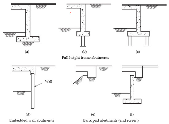

The movements in full height frame abutments are accommodated by rotation or flexure of the abutment wall—whereas, in end screen abutments, the abutments can translate in and out of the fill to compensate for the deck movements. PD 6694-1 [24][25] provides further sub-classifications for end screen abutments: bank pad abutments including those supported on the ground or piles as shown in Figure 1 e–g, flexible support abutments as shown in Figure 1 h, and semi-integral abutments as shown in Figure 1 i. According to PD 6694-1 [24][25], semi-integral abutments consist of the movement bearings at the connection between the vertical support at the end of the bridge deck and conventional or embedded walls or reinforced soil abutments. The movement bearing connection accommodates the deck expansion and contraction without transferring the effect to the bridge abutment.
3. Geotechnical Guidelines and Practices for the Design of Integral Bridges
Most of the USA states have defined and discussed the integral and semi-integral abutment as the two types of abutment in integral bridges. Here, integral abutment refers to an abutment of an IAB, while semi-integral abutment refers to an abutment of an SIAB. Alaska has discussed only the SIAB [25][31], while Idaho [26][32] and North Dakota [27][33] have discussed only the IAB in their design manuals. Virginia [28][34] and Maine [29][35] have used the term “full integral abutment” instead of “integral abutment”.
For ease of reading, a more detailed summary of the recommendations from several USA state DOTs regarding the types of abutments in integral bridges, limiting criteria for selecting integral bridges, and design parameters and mitigation measures, particularly in respect of geotechnical requirements, are presented in Appendix A , Appendix B , Appendix C and Appendix D .
However, for other types of abutments, such as integral abutments on single rows of piles and embedded wall abutments, and for over-consolidated backfill material, cohesive soil and layered soil, limit equilibrium methods are not adequate. Hence, SSI analysis should be used to calculate the horizontal earth pressure behind integral abutments.
Bridge design engineers in New Zealand generally refer to the Transport Agency (NZTA) Bridge Manual for guidance on the design of integral bridges, including specifications on the lateral earth pressure [30][53]. The geotechnical provisions for calculating the earth pressure distribution behind the abutments of integral bridges are provided in NZTA’s Bridge Manual and NZTA research report 577 [31][54] based on the provisions of BA 42/96 [32][45] and PD 6694-1 [33][52]. It has further emphasized the parameters that need to be considered for the SSI analysis for full height integral abutments founded on a single row of vertical piles and integral embedded wall abutments (which will be discussed in Section 3.9.1 ).
4. Conclusions
This review paper discussed the geotechnical design guidelines and practices for integral bridges in the USA, Australia, New Zealand, Canada, Japan, UK, and a number of European countries. The SSI effects on integral bridges and how they have been incorporated in the design are reviewed. Although the popularity of integral bridges is increasing, the knowledge gaps on the SSI effects and current design guidelines of integral bridges present many challenges for geotechnical engineers in mitigating stress ratcheting, settlement, and pile flexural stiffness and fatigue issues. Therefore, augmenting design guidelines to enhance the applicability of integral bridges and to mitigate the geotechnical problems will help to strengthen the current design practice. The main conclusions drawn from the past studies and current design practices of integral bridges are summarized below: The nomenclatures on integral bridges in the design guidelines are not standardised across different jurisdictions. For example, AASHTO [5] defines an integral bridge as an IAB and does not further sub classify the integral bridges. In European countries, integral bridges are commonly defined as either fully integral bridges or semi-integral bridges based on the structural connection between the bridge deck and abutment, though these are analogous to the definitions of IABs and SIABs, respectively. A portal frame bridge (PFB) in Japan and end screen bridge in Sweden are other prominent examples of disparate terminologies of the integral bridges in different countries. There are also disagreements on the definitions and types of abutments in different states of the USA. In this review, we have attempted to unify some of the nomenclatures. An integral bridge is defined in this paper as a bridge structure where the bridge deck is without any joints for expansion or contraction of the deck and may be further sub-categorised as an integral abutment bridge (IAB) or a semi-integral abutment bridge (SIAB) depending on the connection between deck and abutment. The design method and the design lateral earth pressure distribution behind the abutment (whether SSI is needed or not) are defined with respect to the type of abutments, length, and skew angle limit of integral bridges. In addition, the design practices of integral bridges, including threshold limits on the bridge length and skew angle, and types of abutments, vary across the literature. Knowledge gaps still exist in understanding the effects of different type and geometry of abutment, length and skewness of bridge, type of backfill and SSI. Filling the knowledge gaps is necessary to extend the application and improve the performance of integral bridges. The factors considered and the equations used to calculate the earth pressure distribution behind the integral and semi-integral abutment (see Table A1 in Appendix A ) in the USA vary from state to state. Some states are still using the traditional Rankine and Coulomb active and passive earth pressure theories derived for retaining structures under monotonic loading cases. In addition, the designed abutment displacement is considered as the displacement at the top, irrespective of the mode of displacement and flexibility of the abutment. Moreover, the displacement of the abutment is cyclic in nature, and the abutment displacement also depends on the nonlinear response of the backfill. Most of the design practices lack comprehensive design guidelines on pile foundation for the integral bridges. The types of abutment foundation, restriction on the abutment foundation, and design of the abutment foundation (such as the orientation of the pile, type of pile and embedded length of the pile) have resulted in conflicting practices in some cases. In addition, the transferred effects from the abutment and abutment–soil interaction could have different effects on the pile foundation. Abutment–soil interactions and pile–soil interactions should be investigated in a holistic manner in the design of integral bridges. Measures to reduce adverse SSI effects and the consideration of the SSI in the design of integral bridges are required. Both have been recommended in principle and to a different extent in the design standards. Some standards have advised 3D analysis of the integral bridge system incorporating the SSI (e.g., PD 6694-1 [25] and Massachusetts LRFD Bridge Manual-Part I [40]). However, there is very little information on the 3D coupled analysis of the integral bridge structure and soil. Appropriate guidelines to identify the governing soil parameters and changes in soil behavior during cyclic abutment displacement are needed to develop the numerical soil model to study the SSI mechanism in integral bridges. The numerical studies should be combined with scaled model laboratory experiments and field monitoring of actual integral bridges to gain critical insights into the SSI effects (e.g., as recommended in PD 6694-1 [25]). Seasonal and diurnal temperature cycles cause dissimilar period and amplitude variations in the displacements of the bridge structure. In addition, the superimposed thermal effect (daily and seasonal temperature changes) can have different effects on integral bridges compared to the daily or seasonal thermal changes only. However, design guidelines (such as PD 6694-1 [25] and AASHTO [5]) mainly focus on the effects of the seasonal cycles. In addition, some studies found that the shape of the earth pressure distribution behind the integral abutments depends on the magnitude of the abutment displacement [17]. Some standards (e.g., PD 6694-1 [25]; Massachusetts LRFD Bridge Manual-Part I [40]; Utah Bridge Design Manual [37]) further recommend that the magnitude of lateral pressure should be considered as a function of abutment displacement. These indicate the importance of considering the superimposed effects of seasonal and diurnal temperature cycles in postulating the earth pressure and establishing the bending moment distribution on the integral and semi-integral abutment, abutment foundation, and development of the settlement trough at the bridge approach. The review suggests that the principle of isolation being applied to mitigate SSI effects needs more detailed study. Abutment–backfill separation with the use of compressible inclusion and reinforced backfill (MSE wall) are just two more common approaches to mitigate the soil flow, soil slumping, soil settlement and stress ratcheting effects on integral bridges. Other self-stable backfill systems, e.g., soil-cement column wall [10] and EPS geofoam embankment [15], are potential solutions as well. However, most of these suggestions are derived from the lab experiments and finite element analysis, and no explicit design guidelines for such approaches are yet available. In contrast, Alberta and Manitoba strictly avoided the use of foam material behind the integral abutment, as they can be compressed in the long term, which could develop unequal movements at the bridge abutments. Therefore, most appropriate solutions to minimise the earth pressure behind the abutment need to be explored and discussed in the design guidelines to increase the applicability of the integral bridges, and to substitute the integral bridges as an option for longer traditional bridges.