ATo solve the problem of contamination flashover of a catenary insulator in an electrified railway catenary is a special high-voltage transm, the collision mechanism and deposition characteristics of contamination particles on the insulator surface should be studied to ensure the safe operation of traction power supply systems. This resion line installed above rails and transmits electric energy to electric locomotives or motor train units by makingearch used horizontal and oblique cantilever insulators as objects, and established the collision model between particles and insulator surface under different arrangements. The deposition conditions of particles on the insulator surface were obtained, and the simulation model of insulator contamination accumulation was established by using the Euler two-phase flow. The difference of contamination deposition characteristics between horizontal and oblique cantilever insulators was analyzed with the volume fraction of contact with pantographs. Catenarymination particles as the characterization parameter. By comparing the cantilever insulator with the positive feeder insulators are insul, this study analyzed the influence of shed structure on the contamination equipment of traction power supply systems that mainly serve as mechanical support and electrical insulationdeposition characteristics. Results show that the installation method of an insulator has an impact on the contamination deposition on the insulator surface. When particle size and wind velocity are fixed, the degree of contamination accumulation on the surface of the oblique cantilever insulator is constantly higher than that of the horizontal cantilever insulator. The insulator shed structure also has a certain effect on the contamination deposition on the insulator surface. For the cantilever insulator, the degree of contamination accumulation of the windward side is higher than that of the leeward side. However, for the positive feeder insulator, the degree of contamination accumulation of the windward side is consistently less than that of the leeward side. Measures to deal with contamination flashover of catenary insulator are proposed.
- electrified railway
- catenary insulator
- collision model
- Euler two-phase flow
- contamination deposition characteristics
1. Definition
The research can further improve the existing contamination deposition mechanism of insulators, and the results have certain guiding significance for the design, operation, and maintenance of the external insulation of the catenary. Additionally, the maintenance cycle can be formulated according to the distribution of the contamination on the insulator surface to avoid flashover.
2. Introduction or History
An electrified railway catenary is a special high-voltage transmission line installed above rails and transmits electric energy to electric locomotives or motor train units by making contact with pantographs [1]. Catenary insulators are insulation equipment of traction power supply systems that mainly serve as mechanical support and electrical insulation [2]. Insulators are exposed to the atmosphere at all times to enable the easy deposition of contamination particles in the air on the insulator surface with the airflow, and the contamination contains a large amount of soluble substances. In humid environments such as those affected by rain, snow, and fog, they easily form a high conductivity dielectric layer [3,4]; hence, the increase in the insulator partial leakage current leads to a decline in insulation performance, thereby easily generating arc and even flashover [5,6,7,8]. Contamination deposition on the insulator surface is the fundamental factor inducing contamination flashover. Therefore, the collision mechanism and deposition characteristics of particles on the insulator surface should be studied for the insulation design of catenary and the formulation of anti-contamination flashover measures [9,10].
Many studies have been conducted on collision theory and the contamination deposition characteristics of particles on an insulator surface. Li et al. established the collision model between particles and insulator surface, analyzed the collision and adsorption movement of particles on the insulator surface, formulated the adsorption criterion between particles and insulator surface, and considered the corresponding effects of particle size, wind velocity, and humidity. He believed that the smaller the particle size, the higher the humidity, and the higher the wind velocity, the easier the particles are to be adsorbed [11]. Horenstein et al. studied the collision of charged insulator particles through experiments and theories. We obtained the relationship between the influence of wind force on the particle trajectory and the particle size, and proposed a model for quantitative prediction of the DC insulator contamination on transmission lines [12]. Hernandez et al. conducted the contamination test on the surface of the suspension insulator. The study found that the contamination accumulation on the insulator surface is serious when the shed structure is complex and many ribs exist on the lower surface. The structure of the insulator shed with less contamination accumulation on the insulator surface is simple, and the shed surface is smooth [13]. Jiang et al. regarded the insulator surface as an infinitely large flat plate, and established a collision model between the particles and insulator surface. The deposition conditions of the particles are obtained from the perspective of torque balance that consider the rolling of particles on the insulator surface. When the adsorption torque of the particles is higher than the sum of the frictional stress, drag stress, and elastic moment of the particles, the particles will be deposited on the insulator surface. Therefore, particle size is the critical value for deposition when it is 25 μm. If the particle size is below 25 μm, then the particles are deposited on the insulator surface [14]. Lv et al. considered the surface energy of the insulator surface, regarded the insulator as an infinitely large flat plate, and established a collision model between the particle and insulator surface from a three-dimensional perspective. The deposition conditions of particles are obtained according to their force balance. If the kinetic energy of all forces acting on the particles is higher than the energy of the particles before collision on the insulator surface, then the particles are eventually deposited on the insulator surface [15,16]. In the preceding research, the main object was the insulators in the power system environment and the arrangement of the insulators was vertical installation, so the application of the results is limited. To date, there is still a lack of research on the contamination deposition of an insulator in a catenary environment and the collision theory of particles on the insulator surface for the arrangement of the insulator.
23. Data, Model, Applications and Influences
2.1.Theory of Particle Collision and Deposition on Insulator Surface
Various installation methods are used for catenary insulators including cantilever insulators installed horizontally and obliquely, and positive feeder insulator strings installed vertically. Figure 1 shows the site chart of electrified railway catenary insulators. The particles are infinitely small relative to the insulator, and the shed occupies most of the insulator area, so the insulator is considered as an infinite flat plate when establishing the collision model. As the insulator sheds are about perpendicular to the central axis of the insulator, in the preceding research, the insulator arranged vertically was often considered as a horizontal infinite flat plate [18]. However, the installation methods of catenary cantilever insulators are unique, hence, the research should consider the installation method of the insulator.
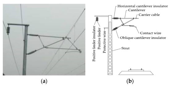
Figure 1. Insulators of the electrified railway catenary: (a) insulator in the working state; (b) catenary structure chart.
This study assumes that the particle shape is spherical. For horizontally installed insulators, the surface of the insulator sheds was regarded as an infinitely large plate placed vertically when establishing a collision deposition model. For the same reason, the inclination angle for an insulator installed obliquely was assumed to be φ, and the insulator was regarded as an infinitely large flat plate with an inclination angle of 90°−φ. Figure 2 illustrates the collision model between the particles and insulator surface.
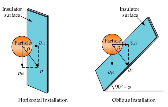
Figure 2. Collision model between the particles and insulator surface.
The assumption was that the particles collide with the insulator surface at the horizontal and vertical velocities of vx1 and vy1, respectively, and assumed that the particles were round spheres, and adopted a hard ball model (i.e., particles do not deform when they collide). This study took a horizontally installed insulator as an example to analyze the collision deposition process between the particles and insulator surface.
The collision deposition process of the particles and insulator surface can be divided into four stages: injection, collision, recovery deformation, and ejection. When the cantilever insulator is installed horizontally, the insulator can be assumed as an infinitely large flat plate with the particle size relative to the insulator surface. Figure 3 shows the schematic of the collision deposition of the particles and insulator surface.
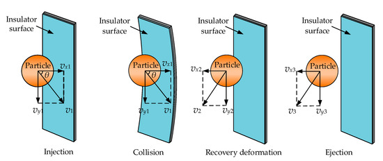
Figure 3. Schematic of the particle collision deposition.
Injection stage: The particles are injected on the insulator surface at a horizontal velocity vx1, vertical velocity vy1, and collision angle of θ.
Collision stage: The particles collide with the insulator surface in an inelastic manner. The horizontal velocity of the particles gradually decreases. When the elastic deformation on the insulator surface is the maximum, the normal velocity of the particles is 0.
Recovery deformation stage: When the horizontal velocity is 0, the particle receives the largest elastic force on the insulator surface. At this time, the particle moves in a horizontal direction. When the insulator wall is restored to deformation, the elastic force becomes 0, and the horizontal and vertical velocities of the particles are vx2 and vy2, respectively.
Ejection stage: The particles are ejected outward at a velocity v2 and are bound by adhesion. If the particles can overcome the adhesion of the insulator surface, then they will bounce back in the air. However, if the particles cannot overcome the adhesion of the insulator surface, then they will be deposited on the insulator surface.
After the particles are injected on the insulator surface at the horizontal and vertical velocities of vx1 and vy1, respectively, then the particles are subjected to gravity, friction, and gas drag in the vertical direction, and the adhesion and elastic force of the insulator surface in the horizontal direction.
Some of the particles will adhere to the surface of the insulator when it comes into contact with the insulator surface. The adhesion force mainly includes the Van der Waals, electrostatic, and capillary forces. The Van der Waals force action begins to appear only when the distance between the particle and insulator surface is below 100 nm and increases as the distance decreases. This action is the main component of adhesion. The electrostatic force is due to the potential difference between the particles and plate, and other factors dominate after adhesion occurs. For the capillary force, the particles and insulator surface will form a liquid bridge after the relative humidity is above 50%, and the main influencing factor is related to air humidity. Figure 4 shows the schematic of the adhesion of particles to the surface of objects.
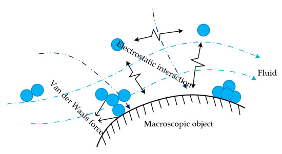
Figure 4. Schematic of the surface adhesion.
References
- China Railway Corporation. The Technology of High-speed Railway Catenary; China Railway Press: Beijing, China, 2014; pp. 1–6.
- Zhao, S.; Zhang, C.; Zhang, Y.; Wang, S.; Influence of partial arc on electric field distribution of insulator strings for electrified railway catenary. Energies 2019, 12, 3295.
- Skopec, A.; Wankowicz, J.G.; Sikorski, B.; Electric field calculation for an axially-symmetric insulator with surface contamination. IEEE Trans. Dielectr. Electr. Insul. 1994, 1, 332–339.
- Bo, L.; Gorur, R.S.; Modeling flashover of AC outdoor insulators under contaminated conditions with dry band formation and arcing. IEEE Trans. Dielectr. Electr. Insul. 2012, 19, 1037–1043.
- Zhang, Z.; You, J.; Wei, D.; Jiang, X.; Zhang, D.; Investigations on AC pollution flashover performance of insulator string under different non-uniform pollution conditions. IET. Gener. Transm. Distrib. 2016, 10, 437–443.
- Xu, J.; Yin, F.; Li, L.; Wen, Q.; Wang, H.; Liu, S.; Jia, Z.; Farzaneh, M.; Wet snow flashover characteristics of 500-kV AC insulator strings with different arrangements. Appl. Sci. 2019, 9, 930.
- Jiang, X.; Wang, Q.; Zhang, Z.; Hu, J.; Hu, Q.; Zhu, C.; Ion migration in the process of water freezing under alternating electric field and its impact on insulator flashover. Energies 2017, 10, 61.
- Dong, H.; Zhang, Y.; Dou, J.; Dong, H.; Su, K.; Numerical analysis of contamination characteristics of new type insulator for catenary cantilever. High Volt. Eng. 2019, 45, 2267–2275.
- Sun, J.; Gao, G.; Zhou, L.; Wu, G.; Pollution accumulation on rail insulator in high-speed aerosol. IEEE Trans. Dielectr. Electr. Insul. 2013, 20, 731–738.
- Jiang, Z.; Jiang, X.; Guo, Y.; Hu, Y.; Meng, Z.; Pollution accumulation characteristics of insulators under natural rainfall. IET. Gener. Transm. Distrib. 2017, 14, 1479–1485.
- Li, H.; Lai, J.; Lei, Q.; Deng, S.; Liu, G.; Li, L.; Collision and adsorption of pollution particles on the surface of electrical insulator. High Volt. Eng. 2012, 38, 2596–2603.
- Horenstein, M.N.; Melcher, J.R.; Particle contamination of high voltage DC insulators below corona threshold. IEEE Trans. Electr. Insul. 1979, 6, 297–305.
- Hernandez-Corona, R.; Ramirez-Vazquez, I.; Montoya-Tena, G. Evaluation of 23 kV insulator profiles with different pollution levels. In Proceedings of the 2004 IEEE International Symposium on Electrical Insulation, Indianapolis, IN, USA, 19–22 September 2004; pp. 304–307.
- Jiang, Z.; Jiang, X.; Jiang, Y.; Li, Y.; Natural contamination characteristics of suspension insulator in Hunan Province. J. Cent. South Univ. (Sci. Tec.) 2018, 49, 1683–1690.
- Lv, Y.; Li, J.; Zhao, W.; Model optimization of pollution deposition criterion of insulators based on energy. IEEE Trans. Dielectr. Electr. Insul. 2017, 24, 2920–2929.
- Zhang, M.; Wang, R.; Li, L.; Jiang, Y.; Size distribution of contamination particulate on porcelain insulators. Coatings 2018, 8, 339.
- Slama, E.A.; Beroual, A.; Hadi, H.; Influence of pollution constituents on DC flashover of high voltage insulators. IEEE Trans. Dielectr. Electr. Insul. 2013, 20, 401–408.
- Lv, Y.; Zhao, W.; Yan, W.; Liu, Y.; Optimization of the contamination particle deposition model based on humidity and surface energy. Appl. Therm. Eng. 2019, 157, 113734–113741.