Polymer electrolyte membrane fuel cells (PEMFCs) have been considered as electric power sources for cars, as well as stationary and portable power sources, due to their high energy efficiency, ease of operation, and environmental friendliness. Furthermore, as a promising power source, integrating PEMFCs into microgrids, which are a common structure in the smart grid framework, has been gaining traction around the world, encouraging the usage of hydrogen energy.
- fuel cells
- PEM
- degradation
- durability
- test protocol
- hydrogen
1. Introduction
Different methods for assessing the durability of PEMFCs have been developed in the United States, the European Union, Japan, and China. These methods are designed to collect enough data about the cell/stack in order to understand its efficiency and durability before it fails. They also have a method for determining the cell/age, and stacks related to changes in cell/stack performance over time [9][1]. According to the US Department of Energy, a metric is used until the cell/stack either accumulates a certain number of cycles or fails to meet a performance criterion, such as a cumulative 20% decline in power or a 10% loss of average cell voltage from initial voltage under cycling conditions [7,9,10][2][1][3].
An effective durability test can provide PEMFC lifetime data, which can be used to evaluate and analyze PEMFC lifetime degradation using lifetime degradation models based on the data. Durability tests can also serve as a solid foundation for testing the degradation behaviors of various components in PEMFCs. The numerous durability tests available vary greatly. Long-term durability tests are time-consuming and expensive, and they often produce lifetime results that are too late to monitor the advancement of fuel cell technology [4].
Methods to evaluate the durability of PEMFC cell/stacks for automotive applications have been suggested by institutions and organizations in India, South Korea, and Russia, and more remarkable in the United States, the European Union, Japan, and China [11][5]. In particular, the Dynamic Stress Test (DST) of the U.S. Department of Energy (DOE, USA) and the Fuel Cell and Hydrogen Energy Association (FCHEA), the Fuel Cell Technical Team (FCTT) of the U.S. Driving Research and Innovation for Vehicle Efficiency and Energy Sustainability (USDRIVE, USA) Fuel Cell Technical Team, the New European Driving Cycle (NEDC) of the United Nations Economic Commission for Europe (UNECE, EU), the Fuel Cell Testing and Standardization Network (FCTESTNEST) of the International Electrotechnical Commission (IEC, EU) and Fuel Cell Testing and Standardization Network (FC TestNet), the Giantleap of the Fuel Cell and Hydrogen Joint Undertaking, and the JC08 of the Japanese New Energy and Industrial Technology Development Organization (NEDO, Japan), as well as other protocols of Chinese universities, such as those at Tongji University, Tsinghua University, Wuhan University of Technology, and Dalian Institute of Chemical Physics, have been developed.
From multi-megawatt systems for large-scale power generation to small units (e.g., 1 kW) for backup power or micro-combined heat and power (CHP) systems, stationary fuel cells can be used in a wide variety of commercial, manufacturing, and residential applications [7][2]. Since the basic construction and materials of the PEMFC stack for stationary applications are similar to those used in vehicles, durability issues are similar [12][6]. PEMFCs in stationary applications, on the other hand, have much longer lifetimes than those in automobiles. Although the operating conditions of PEMFCs in static applications are normally milder than in vehicles, the 40,000 h lifetime goal cannot be easily tested in actual operation [6,12,13][7][6][8]. Testing protocols for stationary applications have received less development attention than testing protocols for vehicle applications.
2. Main Parameters Influencing Long-Term Durability of Polymer Electrolyte Membrane Fuel Cells (PEMFCs)
Dissolution of Pt is accelerated by voltage cycling, which gives rise to a varying load on the fuel cell; in essence, stop-and-go driving experiences of a fuel cell vehicle can typically generate high voltage load [22][9]. Wang et al. [23][10] reported that dissolved Pt concentration increased when potentials rose from 0.65 to 1.1 V and then decreased at potentials above 1.1 V. In another publication, Pt dissolution took place as potentials that exceeded 0.9 V because electrochemical oxidation of Pt occurred, and Pt oxide instantly formed on the Pt surface [24][11].
Carbon oxidation can occur by heterogeneous water-gas reaction [21,22][12][9]: C + H 2O → CO + 2H + + 2e − , E o = 0.518 V RHE at 25 °C (2) where RHE denotes the reversible hydrogen electrode.
In summary, Table 1 details the primary failure modes for PEM fuel cell components such as the membrane, catalyst/catalyst substrate, GDL, bipolar plate, and sealing material [19,84][13][14].
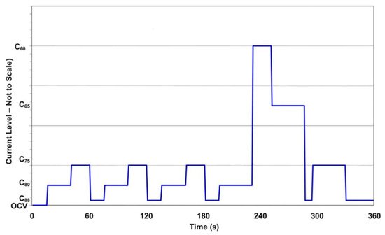
depicts the stack load period used for fuel cell testing based on the initial stack polarization curve and Table 2 shows the current density/time profile. The cycle includes open circuit voltage (OCV), low current, medium current, and high current (16 steps in total). The first stage (15 s) of each 360-s loop is OCV, as shown in Figure 1 Fuel and oxidant compositions, as well as flow rates, will be calibrated at each current level to represent realistic system conditions over a driving cycle. Except for periodic diagnostic testing, the periods would be continuous. Cell resistance and hydrogen crossover, shorting resistance, and a constant-stoichiometry polarization curve would be among the diagnostics.
| Sources | Potential Impurities | |
|---|---|---|
| Hydrogen fuel impurities | Crude oil | CO, NH3, H2S, HCN, hydrocarbons |
| Natural gas | CO, NH3, H2S, HCN, hydrocarbons | |
| Methanol | CO, odorants, alcohols | |
| Biomass | Cations, aldehydes, alcohols, formic acid, NH3, H2S, HCN | |
| Water electrolysis | Anions, cations | |
| Air impurities | Fuel combustion pollution | SOx, NOx, hydrocarbons, soot, and particulates |
| Ambient air, farming | NH3 | |
| Natural sources | Ocean salts, dust | |
| Others | Deicers | NaCl, CaCl2 |
| Fuel cell corrosion products | Cations, anions |
| Component | Failure Modes | Causes |
|---|---|---|
| Membrane | Mechanical degradation | Mechanical stress due to non-uniform pressing and swelling Penetration of the catalyst and seal material traces and foreign particles |
| Chemical degradation | Radical attack Contaminations |
|
| Conductivity loss | Ionic contaminations | |
| Catalyst/catalyst layer CLs | Activation losses | Sintering or de-alloying of electrocatalyst |
| Conductivity loss | Corrosion of catalyst support | |
| Loss of reformate tolerance | Dissolution of alloying elements and contamination | |
| Decrease in mass transport rate of reactants | Mechanical stress | |
| Decrease in water management ability | Changing in hydrophobicity of materials | |
| GDL | Decrease in mass transport | Mechanical stress, compression Degradation of backing material |
| Decrease in water management ability | Mechanical stress Change in hydrophobicity of materials |
|
| Thinning | Corrosion | |
| Bipolar plate | Conductivity loss | Corrosion, oxidation |
| Fracture/deformation | Mechanical stress | |
| Sealing gasket | Mechanical failure and brittleness | Deformation, compression, and chemical reaction |
3. Cell/Stack Durability Test Protocols
The durability testing protocols developed or used for single cells or stacks will be summarized in this section for both vehicle and stationary applications.
Fuel cells for transportation applications, especially for automotive propulsion, may have to operate under different operating and cyclical conditions, including temperatures from sub-zero to above the boiling point of water, relative humidity from ambient to saturation, half-cell voltages from 0 to >1.5 volts. Additionally, the operation conditions during the transient and cyclic modes can change relatively quickly, ranging from high to low voltages, temperatures, humidity, and currents to meet the rapid changes in power demand, some of them severe special materials and the stability of the whole fuel cell system [7,8,118][2][15][16]. Institutions and organizations in India, South Korea, and Russia, and especially in the U.S, EU, Japan, and China, have made significant efforts to propose methods to quantify the durability of the PEMFC cell/stack for automobile applications [11][5].
The DST protocol was developed by the DOE and FCHEA for testing the long-term durability of PEMFC cell/stacks for vehicular applications and comparing cell and stack performance with that specified by the U.S. DOE [2,9,10][17][1][3]. This protocol involves stepping through a series of different current draws typical of vehicle loads based on real power demand from a car during city driving in a typical American urban area [4]. When average voltages are 0.88, 0.80, 0.75, 0.65, and 0.60 V, an initial polarization curve is used to determine current densities, according to the protocol’s guidelines. These current densities are designated C88, C80, C75, C65, and C60, respectively [10][3]. Figure 1
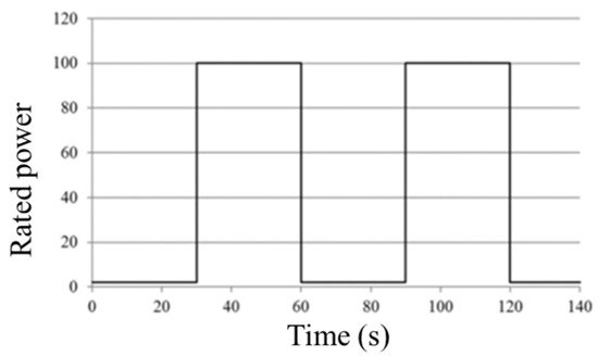
The FCTT proposes two similar-structured cycles for wet and dry conditions [8,9,120][15][1][18]. The quantities of humidification used and the highest current density applied vary. In comparison to the dry cycle, which uses 25% relative humidity and 0.1 A/cm 2 maximum current density, the wet cycle uses 92% relative humidity and a higher maximum current density, 1.2 A/cm 2. The membrane hydration in the dry protocol is dependent on the PEMFC’s self-humidification due to the lower relative humidity. FCTT’s duty cycle profile is depicted in Figure 2 . The PEMFC stack, as shown in Figure 2 , works on a 60 s cycle, alternating between 30 s of idling and 30 s of full power. In the wet process, two load steps of 0.02 A/cm 2 and 1.2 A/cm 2 are fixed, while gas dew point temperatures are set at 83 °C. The load is set at 0.02 A/cm 2 and 0.1 A/cm 2 in the dry cycle, and the gas dew point temperatures are set at 53 °C. The stack temperature in these two procedures is 80 °C, and the gas stoichiometry remains constant throughout.
4. Conclusions
One of the most significant barriers to fuel cell commercialization is durability, as discussed in this review article. We present some of the most important factors influencing the long-term durability of PEMFCs in this study. Degradation of PEMFC materials, operating conditions, water control, and thermal management are among these factors. We discuss PEMFC durability test protocols for transportation applications developed by leading organizations, institutes, and universities around the world, such as the DOE, FCHEA, USDRIVE, UNECE, FC TestNet, IEC, and Japanese NEDO and Chinese universities including Tongji University, Tsinghua University, Wuhan University of Technology, and the Dalian Institute of Chemical Physics. These protocols were created to mimic real-world driving situations. However, they are not meant to be comprehensive for all driving situations encountered in the real world, such as long periods of idling due to traffic jams, etc. Researchers must make adjustments to adapt current operating conditions to test objectives. In addition, the protocols for reliability testing PEMFC stationary applications are briefly discussed. We hope that the results of this research will help to speed up the commercialization of PEMFCs.
References
- Bloom, I.; Basco, J.K.; Walker, L.K.; Malkow, T.; DeMarco, G.; Saturnio, A.; Tsotridis, G. Fuel Cell Testing Protocols: An International Perspective, Joint ANL-JRC Scientific and Technical Report; Argonne National Laboratory: Argonne, IL, USA, 2013.
- Fuel Cells Section. In Multi-Year Research, Development, and Demonstartion Plan; U.S. Department of Energy: Washington, DC, USA, 2015; pp. 1–58.
- U.S. Department of Transportation. Fuel Cells for Transportation Applications; Report No. FTA-TRI-IL-26-7006-2009.1; U.S. Department of Transportation: Washington, DC, USA, 2009.
- Chen, H.; Song, Z.; Zhao, X.; Zhang, T.; Pei, P.; Liang, C. A review of durability test protocols of the proton exchange membrane fuel cells for vehicle. Appl. Energy 2018, 224, 289–299.
- Wargo, E.A.; Dennison, C.R.; Kumbur, E.C. Durability of Polymer Electrolyte Fuel Cells: Status and Targets; Elsevier Inc.: Amsterdam, The Netherlands, 2012; ISBN 9780123869364.
- Büchi, F.N.; Inaba, M.; Schmidt, T.J. Polymer Electrolyte Fuel Cell Durability; Springer: Berlin/Heidelberg, Germany, 2009; ISBN 9780128114599.
- Stationary PEM Fuel Cells with Lifetimes beyond Five Years. Available online: https://cordis.europa.eu/project/id/256721 (accessed on 1 February 2021).
- Fuel Cells and Hydrogen Joint Undertaking Programme Review Report; FCH-JU Programme Office: Brussels, Belgium, 2018; ISBN 9789292461362.
- Sasaki, K.; Shao, M.; Adzic, R. Dissolution and stabilization of platinum in oxygen cathodes. Polym. Electrolyte Fuel Cell Durab. 2009, 7–27.
- Wang, X.; Kumar, R.; Myers, D.J. Effect of voltage on platinum dissolution relevance to polymer electrolyte fuel cells. Electrochem. Solid-State Lett. 2006, 9, 225–227.
- Ota, K.; Koizumi, Y. Platinum dissolution models and voltage cycling effects: Platinum dissolution in polymer electrolyte fuel cell (PEFC) and low-temperature fuel cells. Handb. Fuel Cells 2010, 1–7.
- Dhanushkodi, S.R.; Tam, M.; Kundu, S.; Fowler, M.W.; Pritzker, M.D. Carbon corrosion fingerprint development and de-convolution of performance loss according to degradation mechanism in PEM fuel cells. J. Power Sources 2013, 240, 114–121.
- Wu, J.; Yuan, X.Z.; Martin, J.J.; Wang, H.; Zhang, J.; Shen, J.; Wu, S.; Merida, W. A review of PEM fuel cell durability: Degradation mechanisms and mitigation strategies. J. Power Sources 2008, 184, 104–119.
- Tsotridis, G.; Pilenga, A.; De Marco, G.; Malkow, T. EU Harmonised Test Protocols for PEMFC MEA Testing in Single Cell Configuration for Automotive Applications; JRC Science for Policy Report; Join Research Centre: Petten, The Netherlands, 2015; ISBN 978-92-79-54132-2.
- Fuel Cell Technical Team Roadmap. Available online: https://www.energy.gov/sites/prod/files/2017/11/f46/FCTT_Roadmap_Nov_2017_FINAL.pdf (accessed on 1 February 2021).
- Jafri, N.H.; Gupta, S. An overview of Fuel Cells application in transportation. In Proceedings of the 2016 IEEE Transporation Electrification Conference and Expo, Asia-Pacific (ITEC), Busan, Korea, 1–4 June 2016; pp. 129–133.
- Borup, R.; Meyers, J.; Pivovar, B.; Kim, Y.S.; Mukundan, R.; Garland, N.; Myers, D.; Wilson, M.; Garzon, F.; Wood, D.; et al. Scientific aspects of polymer electrolyte fuel cell durability and degradation. Chem. Rev. 2007, 107, 3904–3951.
- Fabrice MICOUD, S.R. (CEA) STACKTEST: WP5: International Standard Status Report; Fuel Cells and Hydrogen Joint Undertaking (FCH JU): Zentrum für Sonnenenergie- und Wasserstoff-Forschung Baden-Württemberg (ZSW): Ulm, Germany, 2013.
- Bloom, I.; Walker, L.K.; Basco, J.K.; Malkow, T.; Saturnio, A.; De Marco, G.; Tsotridis, G. A comparison of Fuel Cell Testing protocols—A case study: Protocols used by the U.S. Department of Energy, European Union, International Electrotechnical Commission/Fuel Cell Testing and Standardization Network, and Fuel Cell Technical Team. J. Power Sources 2013, 243, 451–457.