Your browser does not fully support modern features. Please upgrade for a smoother experience.
Please note this is a comparison between Version 2 by Conner Chen and Version 1 by Edgar Franco.
Clay-based polymer nanocomposites are often referred to as polymer layered silicates, nanostructured polymers, or simply polymer nanocomposites. These polymers are reinforced with inorganic particles containing at least one dimension in the nanometric scale (<100 nm). Compared to traditional composites (macro- or microscale), polymer nanocomposites offer the opportunity to explore new behaviors and functionalities beyond conventional polymers. Nanoparticles often strongly influence the mechanical properties of polymers in very low volume fractions due to the relatively short distance between nanoparticles, molecular compatibility, and interfacial interaction between the particles and the polymer chains.
- polymer-layered silicates
- oMMT
- clay minerals
- mechanical properties
1. Clay-Based Polymer Nanocomposites
Clay minerals are known as phyllosilicates, or lamellar silicates, which are the inorganic particles most commonly used to prepare clay-based polymer nanocomposites [2,3,4]. It is necessary to highlight that the clay particles are not by themselves nanometric scale particles, but instead that they are formed by the stacking of several layers that leads to the development of irregular aggregates, as schematized in Figure 1. Each layer has a high aspect ratio between 100 and 800 nm in length and approximately 1 nm in thickness. Its uniform dispersion within the polymer matrix favors developing a very high interfacial area per unit volume, which is the primary reinforcement mechanism of clay-based polymer nanocomposites. However, the layer dispersion mechanism is complex since different aspects must be considered, and that is why the specialized literature focuses on evaluating processing conditions to achieve the maximum level of dispersion [2,5,6,7,8].
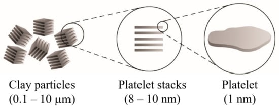
Figure 1.
Schematic representation of the arrangement of the platelet stacks that conform to the clay particles.
Clay layers have a molecular structure based on the stacking sequence. Interesting and complete information is available on the web page of Professor Dorronsoro Fernández from the University of Granada, Spain (Department of Soil Science and Agricultural Chemistry, https://www.edafologia.net/, last visited 12 May 2021).
The basic compositional unit is the silicon–oxygen (Si-O) tetrahedron, as outlined in Figure 2a. It consists of one silicon cation (Si−4) surrounded by four oxygen anions (O−2). Chemically, the Si-O tetrahedron has a net electrical charge of −4, (SiO4)−4, so it is balanced by adding other cations to neutralize their charges (Figure 3a). For this, each vertex of the basal plane belongs to two tetrahedra, since each oxygen is in coordination with two silicones, forming tetrahedral layers distributed under the configuration of hexagons, as can be seen in detail in Figure 4. Sheet silicates (also called layered silicates or phyllosilicates) are obtained when three oxygens on each tetrahedron link to other tetrahedra to form tetrahedral planes.
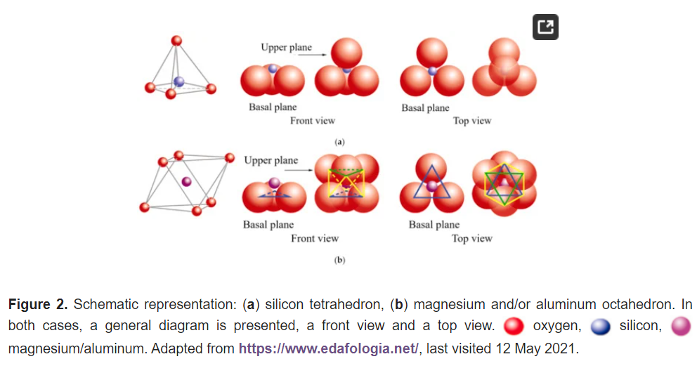
Figure 2. Schematic representation: (a) silicon tetrahedron, (b) magnesium and/or aluminum octahedron. In both cases, a general diagram is presented, a front view and a top view.  oxygen,
  silicon,
  magnesium/aluminum. Adapted from https://www.edafologia.net/, last visited 12 May 2021.
oxygen, silicon, magnesium/aluminum. Adapted from https://www.edafologia.net/, last visited 12 May 2021.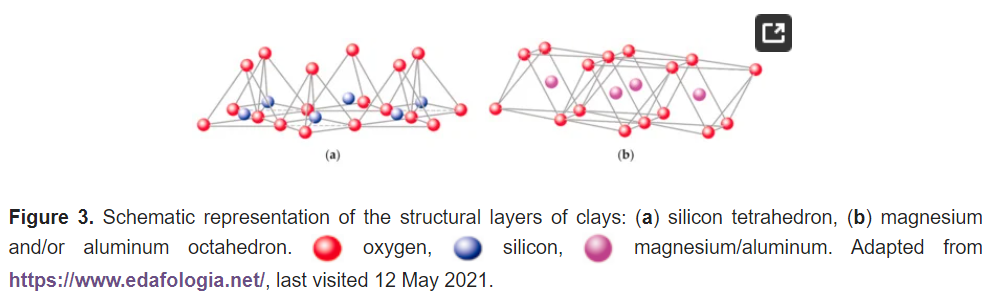
Figure 3. Schematic representation of the structural layers of clays: (a) silicon tetrahedron, (b) magnesium and/or aluminum octahedron. oxygen, silicon, magnesium/aluminum. Adapted from https://www.edafologia.net/, last visited 12 May 2021.
oxygen, silicon, magnesium/aluminum. Adapted from https://www.edafologia.net/, last visited 12 May 2021.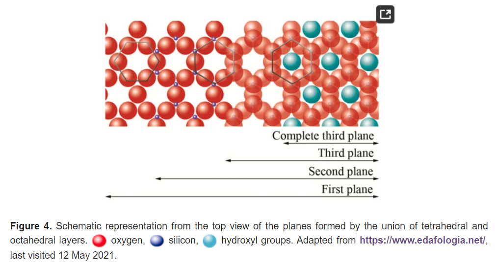
Figure 4. Schematic representation from the top view of the planes formed by the union of tetrahedral and octahedral layers. oxygen, silicon,  hydroxyl groups. Adapted from https://www.edafologia.net/, last visited 12 May 2021.
oxygen, silicon, hydroxyl groups. Adapted from https://www.edafologia.net/, last visited 12 May 2021.Sheet silicates are planar structures containing different kinds of layer that can accommodate cations of all sizes. Tetrahedral layers (labeled T in this work) consist primarily of SiO4 tetrahedra. Octahedral layers (labeled O in this work) contain divalent and trivalent cations (Mg2+ or Al3+) in 6-fold coordination, where each octahedron is supported on one of its faces, which represents the octahedral basal plane, as schematized in Figure 2b. Octahedral sheets are composed of individual octahedrons that share edges composed of oxygen and hydroxyl anion groups, with Mg or Al typically serving as the coordinating cation, as presented in Figure 3b. In two dimensions, anions can fit together in symmetrical patterns to form hexagonal patterns (Figure 4).
In three dimensions, tetrahedral (T) and octahedral (O) layers may stack in various ways. The arrangement of both layers can be better understood if they are represented through atomic planes, as outlined in Figure 5.
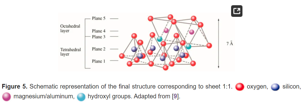
Figure 5. Schematic representation of the final structure corresponding to sheet 1:1. oxygen, silicon, magnesium/aluminum, hydroxyl groups. Adapted from [9].
oxygen, silicon, magnesium/aluminum, hydroxyl groups. Adapted from [9].The first plane corresponds to the basal plane of the tetrahedral layer. Silicon atoms are placed in the second plane, occupying part of the space in the basal plane of each tetrahedron (Figure 4). In a third plane, the unshared oxygens (also called apical oxygen) are located just above the silicon, ending up occupying the remaining space, as depicted in Figure 4. In this way, the arrangement of these three planes constitutes the fundamental unit of the tetrahedral layers (Figure 5).
The union between tetrahedral and octahedral sheets occurs with the apical oxygen, linked to Mg2+ or octahedral Al3+. However, not all the vertices of the octahedral basal plane, formed in part by the apical oxygen, would be shared with the silicon atoms contained in the tetrahedra, so the charge balance occurs when they bind to a hydrogen atom (H), forming hydroxyl groups (OH), as shown in Figure 4 and Figure 5. Thus, the basal plane of the octahedron forms part of the superior plane of the tetrahedra and completes the third plane. It should be noted that all planes represent a hexagonal lattice, while the third plane forms a centered hexagonal lattice, as shown in Figure 4.
The fourth plane consists of the arrangement of octahedral Mg2+ or Al3+ atoms. These atoms are located in the small free spaces left by every two apical oxygens and one OH group, as shown in Figure 6.
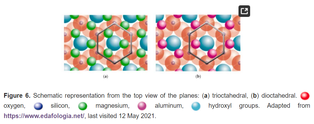
Figure 6. Schematic representation from the top view of the planes: (a) trioctahedral, (b) dioctahedral. oxygen, silicon,  magnesium, aluminum, hydroxyl groups. Adapted from https://www.edafologia.net/, last visited 12 May 2021.
oxygen, silicon, magnesium, aluminum, hydroxyl groups. Adapted from https://www.edafologia.net/, last visited 12 May 2021.The octahedral Mg2+ covers all positions in the trioctahedral plane (Figure 6a). However, the octahedral Al3+ covers just two positions of three vacancies, and it is called the dioctahedral plane (Figure 6b). Nonetheless, this plane is within hexagonal networks.
The fifth plane corresponds to the superior plane of the octahedra (showed in Figure 5). If the structure ends in this plane, the clay has a T:O sequence (also known as 1:1 structure). However, if another tetrahedral layer is added, a sandwich-type T:O:T sequence is formed. The 1:1 sheet silicate is 7 Å thick, while the 2:1 sheet silicate is about 9 Å thick (Figure 7). Thus, the sheet silicates originate from the stacking of parallel planes with hexagonal symmetries, alternating the planes of ions (O and OH) and cations (Si4+, Al3+, and Mg2+).
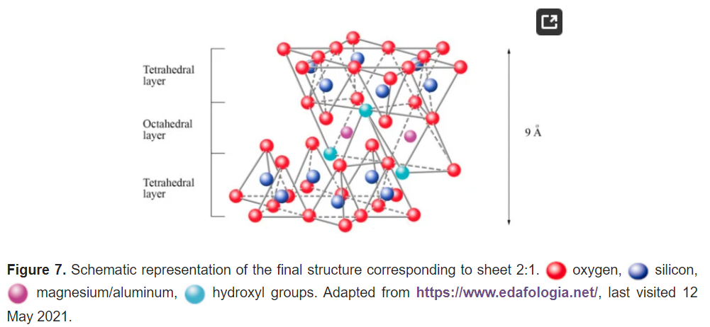
Figure 7. Schematic representation of the final structure corresponding to sheet 2:1. oxygen, silicon, magnesium/aluminum, hydroxyl groups. Adapted from https://www.edafologia.net/, last visited 12 May 2021.
oxygen, silicon, magnesium/aluminum, hydroxyl groups. Adapted from https://www.edafologia.net/, last visited 12 May 2021.Most sheet silicates are monoclinic or triclinic, and have several different polymorphs related to how T:O:T and T:O sheets stack to each other. Figure 8 shows a representative diagram of the 1:1 and 2:1 sheet silicates to better visualize the structural arrangement described. Table 1 shows the classification of clay minerals according to their structural configuration.
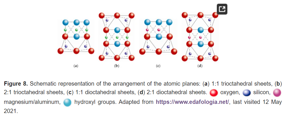
Figure 8. Schematic representation of the arrangement of the atomic planes: (a) 1:1 trioctahedral sheets, (b) 2:1 trioctahedral sheets, (c) 1:1 dioctahedral sheets, (d) 2:1 dioctahedral sheets. oxygen, silicon, magnesium/aluminum, hydroxyl groups. Adapted from https://www.edafologia.net/, last visited 12 May 2021.
oxygen, silicon, magnesium/aluminum, hydroxyl groups. Adapted from https://www.edafologia.net/, last visited 12 May 2021.Table 1.
Classification of clay minerals.
| Structure | Dioctahedral | Trioctahedral |
|---|
| T:O | Kaolinite group [10,11,12,13,14,15,16,17,18,19,20,21,22,23,24,25,26] | Serpentine group [27,28,29] |
| Pyrophyllite | Talc | |
| T:O:T | Smectite group [30,31,32,33,34,35,36,37,38,39,40,41,42,43,44] | |
| Montmorillonite [45,46,47,48,49,50,51,52,53,54,55,56,57,58,59,60,61,62,63,64,65,66,67,68,69,70,71,72,73,74,75,76,77] | Saponite | |
| Beidellite | Hectorite | |
| Nontronite | Stevensite | |
| Vermiculite group [14,78,79,80,81,82] | ||
| Illite | ||
| Mica group [81,83,84,85,86,87,88,89,90,91,92,93,94,95,96,97,98,99,100,101,102,103,104,105,106,107,108,109,110,111,112,113,114,115,116,117,118,119,120,121,122,123,124,125,126] | ||
| Muscovite | Biotite | |
| Paragonite | Phlogopite | |
| Lepidolite | ||
| T:O:T:o | Chlorite group [127,128,129,130,131,132,133,134,135] | |
| Paligorskite | Sepiolite | |
Montmorillonite (discovered by Damour and Salvetat in Montmorillon, France) is currently the most widely used mineral clay to prepare polymer nanocomposites. It is a smectite-type clay belonging to the 2:1 sheet silicates and is composed of aluminosilicates (Al3+). Montmorillonite clay has a high reaction capacity, exceptional resistance, and a large aspect ratio.
1.1. Cation Exchange Capacity
The ability to absorb a certain amount of cations and retain them in an exchangeable state is known as the cation exchange capacity (CEC), expressed in terms of milliequivalents per 100 g (meq/100 g) {Formatting Citation}. The charge of the layer is not locally constant as it varies from layer to layer and must instead be considered an average value over the whole crystal. The importance of knowing the CEC is that the sheets are not electrically neutral due to isomorphic substitutions, where others replace cations such as Si4+ with a lower charge (Al3+), promoting an excess of negative charge. In this case, the load balance is maintained by the presence of individual cations (as in the micas group) or hydrated cations (as in the case of vermiculites and smectites) in the interlaminar space, which is the existing space between two consecutive sheets, also known as “galleries” (Figure 9a). When the hydrated cations are ion-exchanged with organic cations such as more bulky alkylammonium, it usually results in a larger interlayer spacing.
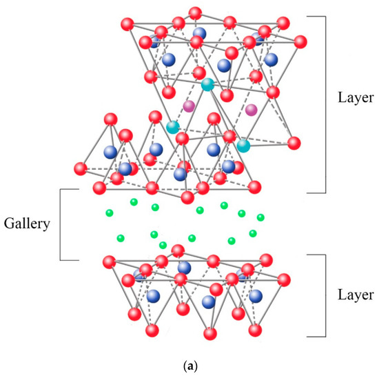
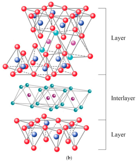
Figure 9. Schematic representation of the clay structure whose charge balance is maintained by: (a) interchange cations, (b) interlaminar octahedral layer. oxygen, silicon, magnesium/aluminum, hydroxyl groups. Schematic sketch based on Beyer [136] with permission from Elsevier.
oxygen, silicon, magnesium/aluminum, hydroxyl groups. Schematic sketch based on Beyer [136] with permission from Elsevier.Among the most frequent interlaminar cations are alkalines (Na+ and K+) and alkaline earth (Mg2+). The hydrated cations such as water and different polar liquids increase the interlaminar space by swelling effect. If the interlaminar cations coordinate with OH groups, an octahedral layer would be formed within the interlaminar space (as chlorites, Table 1), developing structures T:O:T:o or 2:1:1, as represented in Figure 9b. In this case, the number 2 represents the two tetrahedral layers, while 1:1 indicates that the layers of the octahedra differ from each other since the interlaminar octahedra do not share vertices with the tetrahedra.
The bonding forces that join the sheets with the interlayer are weaker than those existing between the ions of the same sheet, so the phyllosilicates have a clear parallel direction of exfoliation.
1.2. Coupling Agents
In the first instance, clay minerals can only be miscible with hydrophilic polymers. Therefore, the use of coupling agents is necessary to make both phases compatible. These agents are fundamental molecules constituted by a hydrophilic functionality (related to clays) and by an organophilic functionality (related to the polymer), which favors the molecular compatibility between the sheets of the clay and the polymer chains.
The first coupled agents used to obtain nanocomposites were amino acids [137]. However, the most popular are alkylammonium ions, since they can easily be exchanged with the cations in the galleries. The alkylammonium ions are primary alkylamines [138,139]. Its basic formula is:
where n represents the chain length, which ranges from 1 to 18 carbons. Lan et al. [140] highlighted that the exfoliation of the sheets is favored when ions with a chain length greater than eight carbon atoms are used, while with shorter chains, it led to the formation of agglomerated structures.
CH3−(CH2)n−NH3+
(1)
Ideally, the alkylammonium ions can be accommodated in various ways within the galleries, depending on the charge density of the clay minerals. Thus, the ions adopt monolayer, bilayer, or paraffin-like monolayers [141], as outlined in Figure 10.
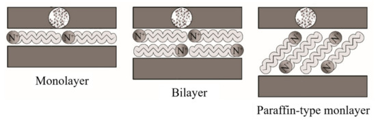
Figure 10. Schematic representation of the configuration of alkylammonium ions within the galleries of clays. Schematic figure based on Lagaly [142] with permission from Elsevier.
1.3. Nanocomposite Structures
Depending on the nature of the composite constituents (layered silicate, organic cation, and polymer matrix) and the method of preparation, three main types of composite may be obtained. Thus, polymer nanocomposites can be classified according to their morphology into agglomerates, intercalated, and exfoliated structures, as represented in Figure 11.
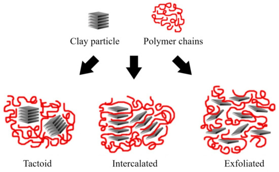
Figure 11. Schematic representation of the nanocomposite structures. Schematic figure based on Beyer [136] with permission from Elsevier.
Agglomerated composites are formed when the polymer is unable to intercalate between the sheets of clay. In this way, two separate and well-defined phases are obtained, where the sheets remain joined and aligned parallel to each other. It is common to classify the properties of these materials within the microcomposites. Some authors refer to the agglomerated composites as tactoids [2,141] or low-packing nanocomposites since there are no variations in the interlaminar space [2,6].
In the case of intercalated composites (also classified as flocculated [3]), the polymer chains are intercalated between the sheets of the clay, increasing the interlaminar space, obtaining a morphology of multiple highly ordered sheets.
Exfoliated nanocomposites contain sheets entirely separated and dispersed within the polymer matrix. This type of exfoliated structure presents relevant mechanical properties due to the high aspect ratio of single sheets. However, this structure is difficult to obtain, and three main processing strategies are commonly used.
1.4. Polymer Intercalation in Solution
The clay mineral is suspended in a polar organic solvent such as water, toluene, ethanol, etc., forming a gel-like structure. Subsequently, the polymer is dissolved and dispersed in the same type of solution, and the reaction is initiated by mixing the solutions, where polymer chains start to fill spaces in the galleries. Then, the solvent is removed by evaporation, obtaining the nanocomposite with a multilayered structure, as outlined in Figure 12.
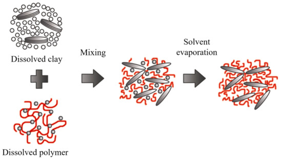
The nanocomposites obtained through this method are highly selective since the polymer and clay minerals possess different physical and chemical properties. The solvent is also essential because it is expensive and not environmentally friendly for large-scale production.
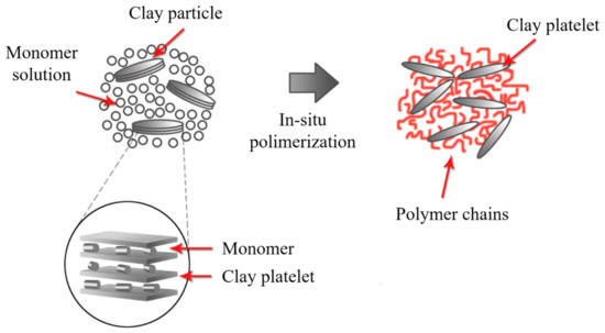
1.5. In Situ Polymerization
In this method, the galleries are expanded using a liquid monomer or a monomer in solution. The polymerization starts by the diffusion of an organic initiator or by catalysis through exchangeable cations (Figure 13) [145]. After polymerization termination, the solvent is evaporated, and the nanocomposite is ready for further modification. The in situ polymerization should be the best method to obtain high intermolecular distance between the clay layers. However, this method contains similar drawbacks to the solution-based method due to large-scale difficulties and environmental considerations.
1.6. Melt Blending Process
This method consists of mixing both phases (polymer and clay minerals) under the action of a high-temperature shear force. Melt intercalation is used for synthesizing thermoplastic polymer nanocomposites at a large scale. This procedure is compatible with industrial processes such as extrusion, making it more economical, convenient, and environmentally friendly because solvents are not required. However, the high temperatures during the extrusion process (up to 220 °C) can degrade the coupling agents (clay minerals modified with alkylammonium).
In a broad definition, the extrusion process refers to any transformation operation in which molten material is forced through a die to produce an article of constant cross-section and, in principle, indefinite length. In addition to plastics, many other materials are processed by extrusion, such as metals, ceramics, or food, obtaining very varied products such as aluminum or PVC window frames, pipes, pasta, etc. From a plastics point of view, extrusion is one of the essential transformation processes. The polymer is generally fed in solid form (commonly dust or pellet) in the hopper section and exits the extruder in the molten state. On some occasions, the polymer can be fed in molten form from a reactor where the extruder acts as a pump, providing the necessary pressure to pass the polymer through the nozzle. The extrusion process is frequently used to mix distinct materials, additives, and fillers to add better performance, reduce costs, and obtain multiple functionalities. These new formulations are further processed to create components or preforms using injection molding, blow molding, or thermoforming techniques.
Although there are various types of extruders, the most widely used are single-screw and twin-screw extruders. Specifically, a single-screw extruder can perform six main functions: transporting the solid material towards the melting zone, melting the polymer, pumping the melt, mixing, degassing, and forming. However, not all of the above functions necessarily take place during the operation of the extruder. According to the purpose, the extrusion process starts with the material feeding system, a melting-plasticizing system, the pumping, and a pressurization system, generating a mixing effect.
It is common to find in the literature that single-screw extruders have poor material mixing due to their design. However, it is essential to consider many other factors that affect the end product, such as the wear of extruder working parts, rotational speed, pressure, nozzle type, and many more. In addition, the extruders are not just used for mixing but also for producing various materials, e.g., direct molding at the nozzle, injection into the die, etc. Ekielski et al. [146] evaluated the wear status of the single-screw extruder working elements based on die pressure and screw load values changes. The changes to these parameters were analyzed as a frequency spectrum using wavelet analysis tools. Due to the dynamic characteristics of the process in determining natural frequencies, the authors used the Morlet wavelet transform, observing that it is possible to accurately evaluate the degree of wear of the friction elements in a single-screw extruder.
Extrusion technology is also used in the food processing industry, known as extrusion-cooking, to produce so-called engineered foods and special feed. Leszek Moscicki and Dick J. van Zuilichem detailed an interesting work related to extrusion-cooking using single-screw extrusion technology [147]. The authors mentioned that the shear exerted by the rotating screw and the additional heating of the barrel promote a rheological modification. The physical aspects such as heat transfer, mass transfer, impulse transfer, residence time, and residence time distribution have a substantial impact on the properties of food and feed during extrusion-cooking and can drastically influence the quality of the final product.
Twin-screw extruders provide a much higher degree of shear than single-screw extruders, and the screw rotation can be co-rotating or counter-rotating. Therefore, this process can be too aggressive for some applications; even so, the high shear promotes twin-screw extrusion to prepare clay-based polymer nanocomposites (Figure 14). However, the single-screw extrusion should be considered for producing starch-based bionanocomposites or other natural composites.
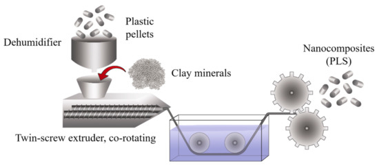
Figure 14. Schematic representation of the production process using twin-screw extrusion.
The literature is consistent in stating that the extrusion process leads to the development of intercalated structures. However, exfoliated structures can develop if there is high molecular compatibility between the phases, and in many instances, the use of additives is required (Figure 15).
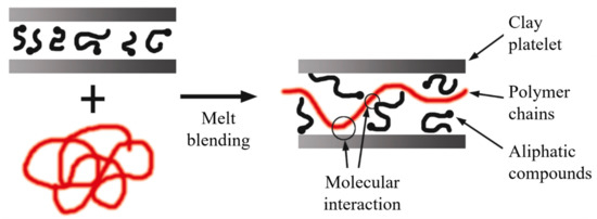
Figure 15. Schematic representation of intercalated structures for melt blending. Schematic figure based on Vaia [148] with permission from American Chemical Society, Copyright 1997.
Some authors [149,150,151] evaluated the influence of the extrusion process on the morphology of polymer nanocomposites. In this way, Dennis et al. [150] observed that a single screw extruder did not provide sufficient shear to separate or fracture the clay layers and did not offer an adequate residence time for layer dispersion. On the other hand, intercalated structures and some agglomerations are present when using a twin-screw extruder under the co-rotating configuration. By using the counter-rotating configuration, a high level of exfoliation was achieved.
Fornes et al. [151] found that the design of the extrusion screws also conditioned the morphology of the nanocomposites. The low- and medium-cut spindles developed interleaved structures, while a high-shear design obtained a high level of exfoliation.
Based on the previous studies, it is possible to consider that using a counter-rotating twin-screw extruder with high- or medium-shear screws should favor the exfoliation of the clay sheets. Nonetheless, it is important to consider that factors such as molecular compatibility and good processing conditions (dosage rate, temperature, and residence time, among others) are necessary for optimal exfoliation [152].
During the twin-screw extrusion process, the exfoliation mechanism begins with the fracture of the particles and the sliding of the sheets until they become stacked sheets of smaller size, as schematized in Figure 16a. This first phase requires a high shear intensity. Subsequently, the polymer is sandwiched between the sheets, taking advantage of their flexibility to increase the distance between them. This second phase requires both high shear and good molecular compatibility (Figure 16b). Finally, the exfoliated sheets are randomly dispersed within the matrix (Figure 16c), requiring adequate residence time [8,153].
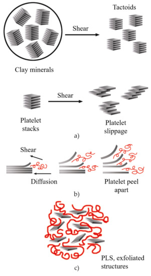
Figure 16. Schematic representation of the exfoliation mechanism of the clay platelets during the twin-screw extrusion process: (a) fracture and sliding of the sheets, (b) intercalation, (c) exfoliation. Schematic figure based on Fornes [154] with permission from Elsevier.
It is important to note that an intense shear does not guarantee a more significant number of exfoliated sheets. Similarly, a longer residence time does not provide better dispersion. For this reason, a large number of studies have focused on developing processing conditions that allow for increasing the level of exfoliation by using the melt intercalation process [1,5,8,151,153,155].
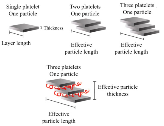
It is possible to consider the average dimensions of each particle: length (ℓp), thickness (tp), and aspect ratio (ℓp/tp). Some authors [8] detailed that the increase in ℓp can be related to the sliding of the sheets that occurred during the twin-screw extrusion process, which can be defined as effective particle length, as shown in Figure 17.
The clay-based polymer nanocomposites have gained the attention of academics and industry in recent decades. Integrating small percentages of clay minerals into the polymer matrix improves the mechanical properties compared to neat polymers. Properly dispersed and aligned clay platelets have proven to be very effective for increasing stiffness without altering the polymer density. There is extensive literature regarding the mechanical properties of polymers enhanced by low clay content, as summarized in Table 2.