Your browser does not fully support modern features. Please upgrade for a smoother experience.
Please note this is a comparison between Version 2 by Lily Guo and Version 1 by Valery Vodovozov.
The adoption of electric vehicles promises numerous benefits for modern society. At the same time, there remain significant hurdles to their wide distribution, primarily related to battery-based energy sources. This review concerns the systematization of knowledge in one of the areas of the electric vehicle control, namely, the energy management issues when using braking controllers. The braking process optimization is summarized from two aspects. First, the advantageous solutions are presented that were identified in the field of gradual and urgent braking. Second, several findings discovered in adjacent fields of automation are debated as prospects for their possible application in braking control.
- electric vehicles
- energy efficiency
2. Braking Tools and Modes
2.1. Braking Controllers
1. Braking Controllers
A braking controller is the core part of the braking system shown in Figure 2. It implements the required braking scenario and activates the EB, FB, or both in order to decelerate a vehicle and absorb its energy. Different classifications of controllers are discussed in reviews devoted to the applied braking techniques that compete in the market.
In [26][1], a classification of controllers suitable for gradual smooth deceleration was proposed. In [27][2], the urgent (called also heavy or emergency) braking mode was studied and appropriate equipment was classified. In [28][3], the same controllers were divided into model-based and rule-based, depending on the algorithms they translate. The former controllers are typically related to physics models with vehicle parameters and tire characteristics. The latter ones are currently predominantly used in vehicles. They process easily accessible data regarding the speeds of the wheels to generate the torque reference signals.
Nevertheless, neither of the above classifications suits this review, which mainly focuses on energy recovery abilities for gradual and urgent vehicle braking. Therefore, a literature analysis related to energy management at braking was carried out according to the following categories [29][4]:
-
By braking modes—for gradual braking and urgent braking;
-
By estimation of the road surface—with no estimation and with surface estimation tools;
-
BY braking torque sharing—with fixed torque distribution and with its smart allocation;
-
By the toolboxes used for simulation—MATLAB/Simulink® (MathWorks, Natick, Massachusetts, USA), AMESim® (Siemens PLM Software, Plano, Texas, USA), CARSim® (Mechanical Simulation Corporation, Ann Arbor, Michigan, USA), and co-simulation, including digital twins;
-
By the tools used for model validation—without verification, with physical imitators, and with real vehicles.
To differentiate between controllers, it would be useful to start with the basics. Given that an initial goal of the braking controller is to initiate vehicle stopping at a required pace, the simplest approach is to use the traditional closed-loop circuit shown in Figure 31a. Here, a controller C compares the reference speed to the real speed of the EV and generates the torque reference to the brake, which produces the reference braking torque. However, the EV cannot process very high braking torque due to its inertia, wheel locking and slip, nonlinearity, and many road obstacles. Therefore, an additional observer OBS has to periodically interrupt or decrease the reference of the conventional controller CC as shown in Figure 31b. Moreover, since energy recovery is in the review focus, the BBS places additional current and SOC restrictions coursed by the EB. For this reason, a TA module fed by an intelligent controller IC can be utilized, as shown in Figure 31c.
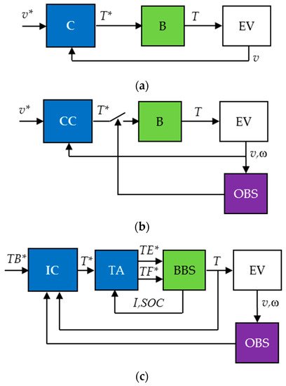
Figure 31. Braking system models: simple (a), conventional (b), and intelligent (c). C, CC, IC—simple, conventional, and intelligent controller; B, BBS—brake and blended braking system; TA—torque allocator; EV—electric vehicle; OBS—observer; v, v*, ω—reference, vehicle linear, and wheel angular speed, TB*, T*, TE*, TF*, T—desired, total, electrical, and friction reference torque and real torque; I, SOC—current of the EM and SOC of the HES.
As a result, all controllers in this research are divided into those that are able to save energy and those that do not have this ability. The former ones are additionally subdivided into conventional (road-independent) and intelligent (road-dependent).
Conventional braking controllers manage either gradual or urgent braking. In their designs, the road surface under the tire is not identified and, therefore, instability of the driving environment is ignored. Depending on the braking scenario, at least three types of the conventional controllers are exploited in transportation, namely, proportional–integral–differential controllers (PIDC) and their varieties, such as PI and PD, threshold controllers (TC), and sliding-mode controllers (SMC).
Intelligent braking controllers take precedence over conventional ones in management of vehicle deceleration on volatile road surfaces, slopes, and aerodynamic conditions. Unlike the previous class, in which the controller is designed for either gradual or urgent braking, intelligent converters can carry out both gradual and urgent braking in a BBS for the sake of boosting energy efficiency. This class involves fuzzy logic controllers (FLC), neural networks (NN) embodied in appropriate neural network controllers (NNC), and model reference controllers (MRC), as well as their multiple options, such as fuzzy PIDC, neuro-fuzzy controllers, and neuro-MRC.
This classification is shown in Figure 42.
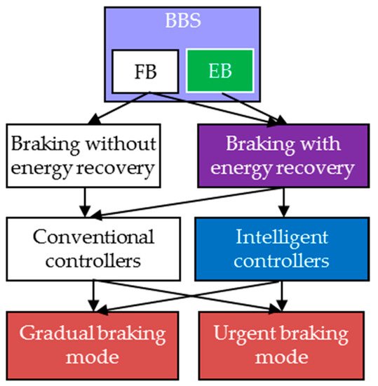
Figure 42. Classification of braking controllers by energy recovery abilities: BBS—blended braking system, FB—friction brake, EB—electrical brake.
Figure 42 can be used to specify the issues addressed in this paper, which focuses on urgent and gradual braking with energy recovery thanks to the maximal involvement of EB under the guidance of intelligent controllers.
To compare different solutions, it was important to validate the results published by different authors. Therefore, both the simulation tools and the model verification tools are carefully analyzed in the review. Taking into account the importance of experimental studies, special attention was paid to hardware-in-the-loop (HIL) [30,31,32,33][5][6][7][8] and real vehicle testing techniques used for verification of the developed systems with respect to most control aspects.
2.2. Gradual and Urgent Braking Modes
2. Gradual and Urgent Braking Modes
Gradual braking control aims to respond to the driver’s accelerator pedal request as accurately as possible. Gradual braking is used to decelerate the car in front of a traffic light, ahead of a pedestrian crossing, in a parking lot, or when driving downhill. This is rather static compared to dynamic mode, suitable for energy optimization with minimal FB involvement. In terms of energy recovery during car deceleration, regenerative EB has many preferences. That is why EV designers, such as [18[9][10],34], applied the EB for vehicle gradual slowing and downhill movement. Several studies were conducted in this direction to minimize the energy lost during the gradual braking [35,36][11][12].
The main difficulty during gradual braking control takes place because the braking system of the road vehicle includes a time-variant and nonlinear plant with significant dead time. Thus, variations in weight, tire–road friction, driveway inclination, wind speed, and other properties significantly affect the braking performance [37][13]. Deviations of many parameters and steering conditions from known values course driving deterioration, resulting in larger overshoot, longer settling times, and sometimes unstable EV behavior. In order to govern vehicle deceleration properly, specific braking controllers were designed that could make decisions on the basis of online solutions of nonlinear equations to accurately activate the brakes.
As opposed to gradual braking, the main target of urgent braking control is to minimize the braking time and distance. The system has to respond as quickly as possible when the driver sharply presses the brake pedal. During urgent braking, the driver’s braking energy request often exceeds the ability of the HES. Despite the fact that EMs are capable of developing great torque rapidly, this is not enough to produce the total braking force needed to ensure rapid stopping of the steerable EV due to the HES overheating and its SOC threshold saturation. As the regenerative power cannot meet the intensive braking requirement, the use of a traditional FB is assumed instead of EB or together with EB to slow the car in the frame of the BBS, which combines FB with EB. In the BBS, the urgent braking and the gradual braking parts are usually separated because of their different targets. Regrettably, the use of FB leads to braking energy wasting and a reduction in the EV lifetime, along with pollution of the environment with tire particles.
Little attention is paid to BBSs that might integrate both the intensive and the gradual braking abilities within a common BBS module. FB and EB have been successfully operated together in only a few cases [38[14][15][16],39,40], in which the BBS was so versatile that it successfully implemented both braking modes. In [41][17], a BBS incorporating a set of electro-hydraulic systems was designed for EVs. As another example, several braking systems of electric buses can be considered [39][15]. Unfortunately, their permanently working FBs badly adjust the braking force and easily lock driving axles.
2.3. Antilock Braking Systems
3. Antilock Braking Systems
The challenge with urgent braking is that the vehicle may skid and its wheels may lock. Thus, a difference can appear between the expected and real distance traveled by a vehicle due to tire slip, which occurs when the wheel rotates slower than the vehicle would normally demand [10][18]. The reason lies in the complex physical processes mediating the tire and road surface contact, which results in wheel sliding or even locking. Due to the tire’s elasticity, it deforms to a greater or lesser extent depending on the road pavement, weather, and wind.
To mitigate slip, antilock braking systems (ABS) are used in road vehicles. Once the brake pedal is pressed suddenly, the braking observer monitors data acquired from the speed sensors located in each wheel hub to determine when a wheel has an improper speed. If wheels slow or stop spinning, the ABS alternately increases and decreases the braking torque in accordance with a particular antilock law. The rapid squeeze and release forces the vehicle to slow down and stop without the wheels ever truly stopping, allowing the driver to maintain steering control [42,43,44][19][20][21].
It is worth noting that execution of the classic ABS is accompanied by at least two issues from the standpoint of energy saving.
First, since the ABS is initially configured for high-speed driving on a straight dry road, it might take a longer time to stop in volatile and unknown road conditions. As soon as snow, rain, or loose gravel appears, the ABS may lengthen the braking time and distance instead of shortening.
Second, to ensure proper management organization, the ABS is often separated in the vehicle braking system, being focused on fast and reliable deceleration. Most ABSs are FB-oriented modules that are not engaged in solving any energy recovery problems.
References
- Kumar, V.; Nakra, B.C.; Mittal, A.P. A review on classical and fuzzy PID controllers. Int. J. Intell. Control Syst. 2011, 16, 170–181.
- Algadah, K.M.; Alaboodi, A.S. Anti-lock braking system components modelling. Int. J. Innov. Technol. Exploring Eng. 2019, 9, 3969–3975.
- Challa, A.; Ramakrushnan, K.; Subramanian, S.C.; Vivekanandan, G.; Sivaram, S. Analysis of thresholds in rule-based antilock braking control algorithms. IFAC-PapersOnLine 2020, 53, 404–409.
- Vodovozov, V.; Raud, Z.; Aksjonov, A.; Petlenkov, E. Fuzzy logic control of electric vehicles in changing braking conditions. In Proceedings of the XI International Conference on Electrical Power Drive Systems (ICEPDS), Saint-Petersburg, Russia, 4–7 October 2020; pp. 1–6.
- Liu, Q.; Sun, Z. Study on electro-hydraulic parallel brake system using HILS. In Proceedings of the IEEE Vehicle Power and Propulsion Conference (VPPC), Harbin, China, 3–5 September 2008; pp. 1–4.
- Varga, B.O.; Moldovanu, D.; Mariaşiu, F.; Iclodean, C.D. Simulation in the loop of electric vehicles. In Modeling and Simulation for Electric Vehicle Applications; Intech Open Access: London, UK, 2016; pp. 1–22.
- Lin, M.; Wang, L.; Cao, W.; Ma, B.; Cai, P. A simulation study of the design and development of vehicles regenerative braking system. Int. J. Simul. Syst. Sci. Technol. 2016, 17, 26.1–26.6.
- Ahmad, F.; Hudha, K.; Mazlan, S.A.; Jamaluddin, H.; Aparow, V.R.; Yunos, M.R.M. Simulation and experimental investigation of vehicle braking system employing a fixed caliper based electronic wedge brake. Simulation 2018, 94, 327–340.
- Chen, Z.; Lv, T.; Guo, N.; Xiao, R.; Shen, J. Study of braking energy recovery of electric vehicles equipped with super capacitor. In Proceedings of the Chinese Automation Congress (CAC), Jinan, China, 20–22 October 2017; pp. 7231–7236.
- Xie, Y.-B.; Wang, S.-C. Research on regenerative braking control strategy and Simulink simulation for 4WD electric vehicle. In Proceedings of the 2nd International Conference on Manufacturing Technologies (ICMT), Lakeland, FL, USA, 15–17 January 2018; pp. 1–6.
- Raud, Z.; Vodovozov, V.; Lillo, N.; Rassõlkin, A. Reserves for regenerative braking of battery electric vehicles. In Proceedings of the Electric Power Quality and Supply Reliability Conference (PQ), Rakvere, Estonia, 11–13 June 2014; pp. 1–6.
- Vodovozov, V.; Lehtla, T. Design considerations for propulsion drives of electric vehicles. In Proceedings of the 14th International Symposium “Topical Problems in the Field of Electrical and Power Engineering”, Pärnu, Estonia, 13–18 January 2014; pp. 35–39.
- Raesian, N.; Khajehpour, N.; Yaghoobi, M. A new approach in anti-lock braking system (ABS) based on adaptive neuro-fuzzy self-tuning PID controller. In Proceedings of the 2nd International Conference on Control, Instrumentation and Automation (ICCIA), Shiraz, Iran, 27–29 December 2011; pp. 530–535.
- Guo, L.; Hui, W. The optimum cooperative controller of the steering/anti-lock braking system of the vehicle using the coordination model. In Proceedings of the International Conference on Mechatronic Science, Electric Engineering and Computer, Jilin, China, 19–22 August 2011; pp. 2031–2034.
- Wang, J.; Qiao, J.; Qi, Z. Research on control strategy of regenerative braking and anti-lock braking system for electric vehicle. In Proceedings of the 27th International Battery, Hybrid and Fuel Cell Electric Vehicle Symposium (EVS), Barcelona, Spain, 17–20 November 2013; pp. 1–7.
- Vodovozov, V.; Aksjonov, A.; Petlenkov, E.; Raud, Z. Neural network-based model reference control of braking electric vehicles. Energies 2021, 14, 2373.
- Yang, Y.; Luo, C.; Li, P. Regenerative braking control strategy of electric-hydraulic hybrid (EHH) vehicle. Energies 2017, 10, 1038.
- Konrad, R. (Ed.) Brakes, Brake Control and Driver Assistance Systems: Function, Regulation and Components; Springer: Friedrichshafen, Germany, 2014; p. 275.
- Bhandari, R.; Patil, S.; Singh, R.K. Surface prediction and control algorithms for anti-lock brake system. Transp. Res. Part C Emerg. Technol. 2012, 21, 181–195.
- Taixiong, Z.; Yage, Z. Development of hardware-in-the-loop and virtual reality co-simulation platform for automotive anti-lock braking system. In Proceedings of the IET International Conference on Information Science and Control Engineering (ICISCE), Shenzhen, China, 7–9 December 2012; pp. 1–6.
- Zhang, X.; Lin, H. UAV anti-skid braking system simulation. In Proceedings of the 37th Chinese Control Conference, Wuhan, China, 25–27 July 2018; pp. 8453–8458.
More