The cusped field thruster is a novel concept of electric propulsion devicewith the advantages of an extremely large thrust throttle ability (more than three orders of magnitude), low complexity, strong robustness and a long lifetime (more than 18,750 h). A cusped field magnetic field is formed in the channel by arranging quasi-periodic permanent magnets around the discharge channel.
- electric propulsion
- cusped field thruster
- HEMPT
- microthruster
- drag-free control
1. Introduction
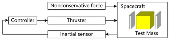
The space-borne gravitational wave detection mission requires several satellites which form several interferometer arms in space. The satellites are linked by bidirectional laser interferometers to measure the micro-position variations between the test masses (TMs) in the satellites [1]. In order to meet the required measurement resolution, the non-conservative forces from the space environment must be shielded to realize the free-flying of the TMs; therefore, the drag-free control system is required [2]. The drag-free control system compensates for the non-conservative disturbance with the micro propulsion system, to make the satellite track the TM in real time and minimize the relative displacement between them [3]. As shown in Figure 1, inertial sensors are applied to measure the real-time relative displacement between the satellite and the TM, and feedback the parameter signal to the controller [4]. The controller then calculates the required thrust and sends control demands to the micro propulsion system. The microthruster generates fast and accurate thrust to compensate the non-conservative force and eliminate the relative displacement. Since the microthruster is the actuator of the drag-free control system, the performance of the control system is limited by the ability of the thruster [5]. In that case, the microthruster is a key technology of the drag-free control system [6].
The gravitational wave detection satellites are affected by 2–30 μN level disturbing influence [7] like fluctuating solar radiation pressure, solar wind and photon pressure. During the mission, the variation would be as small as 0.1 μN with the change of the satellites’ motion and attitude. In addition, the requirements of the laser instruments demand a thruster noise of no more than 0.1 μN. The low-frequency gravitational wave detection mission demands long timescale (1–10,000 s) measurements, which leads to a strong requirement on the thruster lifetime [8]. For example, the LISA (Laser Interferometer Space Antenna) mission [9], put forward by European Space Agency, requires the microthruster to provide 5–30 μN thrust with resolution better than 0.1 μN, a thrust noise below 0.1 μN /Hz 1/2 and a lifetime more than 35,000 h [10].
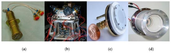
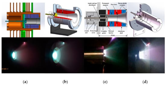
The microthruster development began in the 1960s [11], when research was mostly about the colloid thruster (also called the electrospray thruster) [12] and the pulsed plasma thruster (PPT) [13]. Several microthruster types were successfully applied on small satellites, which majorly operated the attitude control system. In 1964, the drag-free control system concept was raised, which made it possible to conduct high-precision science measurements on orbit [14]. The requirements of high accuracy, low noise, fast response, and wide range thrust were also raised on the microthrusters. With the LISA started in 1993 [15], and the TianQin mission [16] and Taiji mission [17] started in 2014 and 2016, respectively, selections of different microthruster types were ongoing. After the cold gas thruster [18] and the colloid thruster [19] operated successfully on the LISA Pathfinder in 2017 [20][21][20,21], LISA issued four candidate microthruster types, which could possibly be used in the gravitational wave detection mission. These were the cold gas thruster, the colloid thruster [22], the radio frequency ion thruster [23] and the cusped field thruster (HEMPT, High Efficiency Multistage Plasma Thruster) [24], as shown in Figure 2 and Table 1 [25].
| Thruster Type | Technology Readiness Levels |
|---|---|
| Cold gas thruster | 9 |
| Colloid thruster | 7 (head), 5 (feed system) |
| Radio frequency ion thruster | 4 |
| Cusped field thruster | 3 |
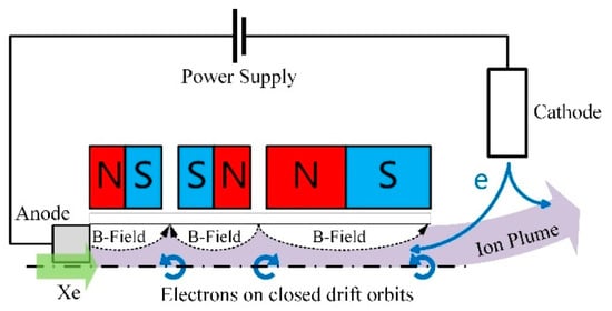
The cusped field thruster is a novel concept of electric propulsion device [26] with the advantages of an extremely large thrust throttle ability (more than three orders of magnitude), low complexity, strong robustness and a long lifetime (more than 18,750 h) [27]. A cusped field magnetic field is formed in the channel by arranging quasi-periodic permanent magnets around the discharge channel, as shown in Figure 3 . The original electrons from the cathode are captured by the magnetic field, and most of them are confined between the magnetic cusps due to the magnetic mirror effect. Collision ionization is thus induced in the channel. Due to the magnetic field lines parallel to the axis, as well as the magnetic mirror effects near the cusps, the plasma is restrained from the channel wall [28].
2. Brief Development of Cusped Field Thruster
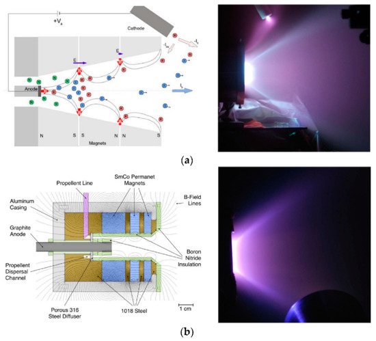
The HEMPT prototype was selected as a priority electric propulsion technology by ESA for its prominent advantages [29][35], and it garnered much attention from international research institutions. As shown in Figure 45 , MIT started their research on this thruster in 2007 and named it the divergent cusped field thruster (DCFT) [30][36]. With the divergent magnet arrangement, DCFT performed the highest anode efficiency of 44.5%, which was comparable to HEMPT 3050 [31][37]. The thruster has also been developed in Stanford since 2012, named the cylindrical cusped field thruster (CCFT) [32][38]. A cylindrical channel was employed in CCFT with a chamfered edge at the exit plane, which aims to ensure that electrons traveling along field lines from the cathode have a path to enter the channel with minimal collisions [33][39]. CCFT achieved an anode efficiency of 21.9% with Kr propellant (while cusped field thruster usually uses Xe propellant for relatively low ionization energy). Research about DCFT and CCFT were majorly investigating the discharge characteristics and physical mechanisms, such as potential distribution, acceleration process, mode transition phenomenon, and oscillation characteristics [34][35][40,41].
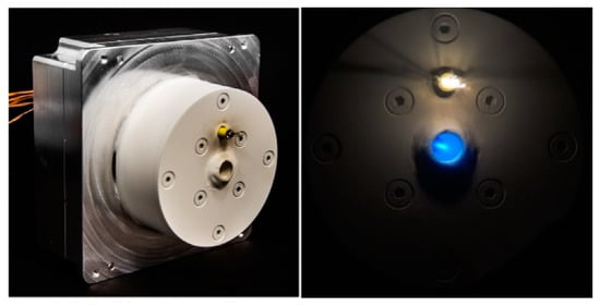
The Harbin Institute of Technology (HIT) started research on the cusped field thruster around 2012, including prototype development, experimental investigations and simulation studies. In order to fulfill the requirements of different space missions, HIT developed cusped field thrusters of 20–110 mN level, 10–60 mN level, 1–20 mN level and 0.5–7 mN level, as shown in Figure 56 and Table 23 . In particular, the 1–20 mN cusped field thruster was designed for the drag-free flight of the earth’s gravity field mission [36][42]. It achieved a continuously variable thrust from 1 to 20 mN with a resolution of better than 19.5 μN and thrust stability of ±5%. These test results showed that large throttling ability is a common advantage of the cusped field thruster, since thrusters of different levels are able to work stably within a wide range of thrust. This advantage is very competitive for drag-free control flights [37][38][43,44].
| Year | Prototype | Anode Voltage (V) | Mass Flow Rate (sccm) | Thrust (mN) | Specific Impulse (s) | Total Efficiency (%) |
|---|---|---|---|---|---|---|
| 2012 | CFT [45] | 100~500 | 20–50 | 20–110 | 500~2300 | 10–35 |
| 2014 | CFT | 100–500 | 10–30 | 10–50 | 500–2200 | 6–35 |
| 2015 | CFT [46] | 300~1000 | 3–11 | 1–20 | 120~1800 | 5–30 |
| 2016 | CFT | 600~1200 | 1–3 | 0.5–7 | 400–2500 | 7–22 |
In recent years, new generation space science experiments, as well as high precision space telescopes [39][47] and space observation missions [40][48], have greatly raised the requirements on microthrusters. Aiming to fulfill the requirements of LISA, Andreas Keller et al. started the downscaling study on the cusped field thruster in 2011 [41][49]. A series of experimental investigations were carried out to analyze the feasibility of cusped field thruster miniaturization. At the same time, simulation works and thruster measurement facilities were also developed. In 2016, Franz Hey from Airbus presented a 29–86 μN micro cusped field thruster with coated discharge channel to enable a minimal wall thickness [42][50], as shown in Figure 67 . The total efficiency is about 7%.
The downscaling research in Europe indicates that in spite of the prominent plasma-confine ability, the cusped field thruster is faced with performance degradation resulting from the scale effects [43][51]. Therefore, the downscaling work on the cusped field thruster is still to be done. Therefore, there is a significant necessity for studies on the different component effects and physical mechanisms in the cusped field thruster.
3. Low Power Cusped Field Thruster Development at HIT
In recent years, research on the cusped field thruster have been majorly focused on the low power types since the demand on low power electric thrusters increased with the development of small satellites. The major research interests include configuration and physical mechanism studies, cusped field thruster downscaling and the recent microwave discharge cusped field thruster concept.
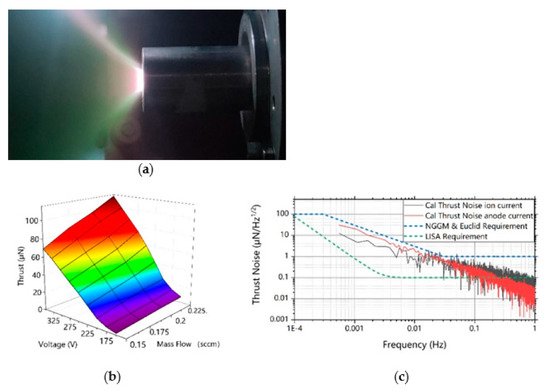
Under the guidance of the previous studies on component geometry, channel materials and variable cross-section configurations, a 4 mm exit diameter cusped field thruster was presented in 2018. The test results show that the thruster performs 1.8 μN to 112.7 μN thrust with mass flow rate from 0.15 sccm to 0.25 sccm and anode voltage from 150 V to 350 V. The power spectral density (PSD) of the thrust calculated by anode current and total ion current is obtained from the time variation of these parameters, as shown in Figure 18 c. However, the μN-level cusped field thruster does not meet the target thrust noise and resolution requirement of typical gravitational wave detection missions. The size effect is still unavoidable for cusped field thruster downscaling, as it leads to problems such as wall loss, electron conduction difficulty and ionization inefficiency.
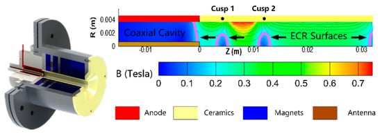
ECR ion source is an effective low-pressure microwave plasma generator with exceptional stability and repeatability [44][75]. The first-generation microwave discharge cusped field thruster was designed with a cylindrical antenna located in the near-anode region. Through this antenna, microwave radiation at 2.45 GHz is transmitted into the 6 mm-diameter thruster channel in TEM coaxial mode. Electrons are heated to a high temperature and inelastic collisions are induced. In a cusped field thruster, several ECR surfaces are formed near the magnetic cusps, as shown in Figure 19 .
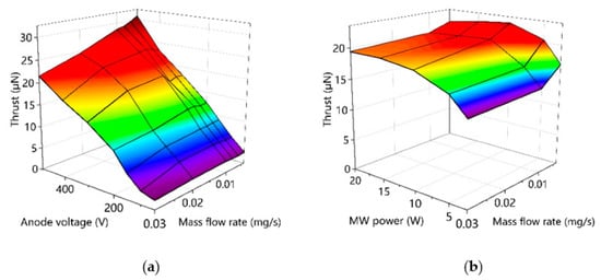
This configuration makes the microwave discharge cusped field thruster achieve a continuously adjustable thrust that ranges from 1.9 to 30.8 μN, with a specific impulse from 70.5 to 804.7 s ( Figure 204 ). Compared with the low power cusped field thruster explored in previous work (27–868 μN thrust and 22–1208 s specific impulse), the minimum thrust is significantly lowered with a higher specific impulse at lower thrust conditions. Another remarkable result is that the thruster is able to work steadily with an extremely low mass flow rate of 0.04 sccm, which is unprecedentedly low for a cusped field thruster. However, this prototype does not perform with high total efficiency, while the thermionic emission cathode is a preliminary model as well [45][78]. Since the extremely low mass flow rate discharge is achieved, which is also found to operate with microwave power as low as 1 W, there could be room to make improvements. Optimization efforts on microwave feeding structure, magnetic topology, components materials and other configurations are still to be done in the future, hopefully to meet the gravitational wave detection mission requirements.
4. Conclusions
The cusped field thruster is a candidate microthruster for the gravitational wave detection mission with advantages of low complexity, potential long life and large throttling ability on thrust. Besides the GW mission, the cusped field thruster also shows competitiveness for small satellite missions and space science missions demanding a drag-free system. This paper presents a brief review of the research on cusped field thrusters at Harbin Institute of Technology since 2012, including efforts on low power prototype iterations, structure configuration optimization, physical mechanism study, thruster downscaling and preliminary investigation of the microwave discharge cusped field thruster.
Prototypes on thrust level from 100 mN to 7 mN are experimentally investigated, and the general large throttling ability is verified. A series of experiments and simulations are carried out to study the operation mechanism, the component effects and the optimization methods of the cusped field thruster. Results show that: A higher downstream magnet ratio leads to flatter exit magnetic separatrix and extension of the ionization region, and, as a result, more focused plume and better performance. A higher magnetic field intensity gives rise to more effective confinement of electrons, and a reduction of propellent utilization due to ionization region narrowness. The main potential drop locates near the channel exit in a cusped field thruster, which makes the exit magnetic separatrix a determinant factor of plume divergence. Thus, plume divergence reduction is achieved through optimization on it. The variable cross-section is applied to change the mass flow flux distribution in the channel, and a spacer with appropriate location contributes to better total performance by enhancing the ionization in the dominant region. Two electron conduction routes are found in the cusped field thruster. The competition between the two electron routes, as well as the two ionization regions, is the intrinsic reason for the mode transition phenomenon.
Cusped field thruster downscaling works are carried out, including investigations on thruster geometry, expanding cross-section configuration and channel wall materials. Results show that: Size effects are significant in cusped field thrusters, but diameter reduction is still necessary for downscaling because of the significant mass flow flux difference. An equilibrium on energy efficiency and propellant utilization should be considered to find out the optimal channel length for a cusped field thruster. The equilibrium on electron temperature and electron loss should also be considered to find out the wall material with an appropriate SEE coefficient. Expanding cross-section configuration contributes to a wider operation range and better mode stability. The DC discharge cusped field thruster is unlikely to meet the ultimate requirements of GW detection mission.
A novel concept of the microwave discharge cusped field thruster is carried out and experimentally investigated. ECR is successfully induced in a low power cusped field thruster, and the ionization enhancement is verified on low mass flow rate conditions. Using a coaxial transmission line resonator (CTLR), the second-generation microwave discharge cusped field thruster performs a 1.9 to 30.8 μN thrust with an extremely low mass flow rate of 0.04 sccm. Further studies and efforts for optimization of the thruster is to be done in future works.