The hydraulic free-piston engine (HFPE) is a kind of hybrid-powered machine which combines the reciprocating piston-type internal combustion engine and the plunger pump as a whole. In recent years, the HFPE has been investigated by a number of research groups worldwide due to its potential advantages of high efficiency, energy savings, reduced emissions and multi-fuel operation.
- hydraulic free-piston engine
- operating characteristics
- research progress
- systematic review
- meta-analysis
1. Introduction
Energy scarcity is an eternal theme for human beings; obtaining energy more efficiently, cleanly and sustainably is a primary concern. The free-piston engine has been attractive to the energy industry because of several advantages, such as a simple structure, a shorter transmission chain and an adjustable compression ratio for different kinds of fuel. However, this engine, as a new concept, has a lot of problems, such as cycle-by-cycle variations, bad stable combustion and flammability.
The free-piston engine is a new kind of engine combining load and internal combustion engines; there are not any crankshafts or connecting rods for a generator or hydraulic pump, so it has less components. Due to no crank-link mechanism, the engine’s speed can stay lower than that of a conventional engine by using the variable pulse width method or another advanced control method.(3)Thermodynamics: The heat release discipline of this engine is more like premixed combustion; the fuel could finish the combustion process during a short time. Hence, this engine has higher thermal efficiency.(4)Discharging: Due to its variable compressor ratio, the discharging characteristics can be optimized by making a control strategy for the corresponding load. On the other hand, if there is no strong coupling relationship between one cycle and the next cycle, then the difference between low speed and high speed is not obvious anymore, so the engine’s discharging can be improved by optimizing one certain speed.(5)Stability: There are a lot of factors affecting this type of engine’s stability, such as fluctuations of the fuel system and fluctuations of the scavenging system—those influences are strong.
2. Overview of HFPEs
At the same time, other national researchers, represented by the German Junkers, also performed research on this engine. The papers related to free-piston machinery and patents sprang up from then on. He began this research in 1922. From then on, Pescara devoted himself to the free-piston machine and applied for a patent of the multistage free-piston air compressor in 1941 [1,2,3][1][2][3].
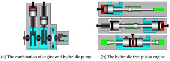
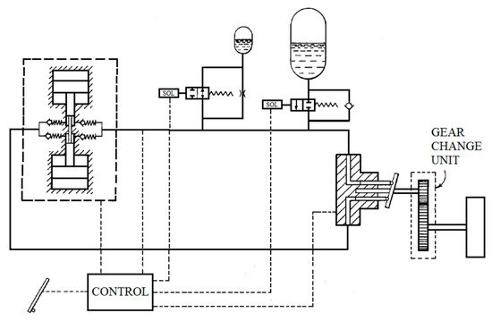
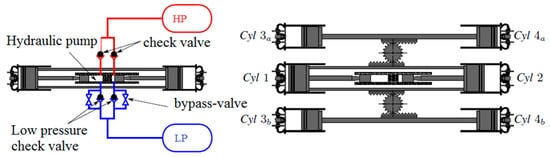
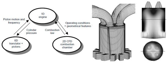
By connecting the pistons with a hydraulic plunger, this engine can translate reciprocating motion into hydraulic energy and output power in a non-rigid pattern. An HFPE does not have any crank-link mechanism or oblique plate mechanism; these two kinds of mechanisms are very common in conventional engines and plunger pumps [4,5][4][5]; the differences between an HFPE and a traditional engine–pump combination are shown in Figure 1. : its load is hydraulic oil with a certain pressure; a hydraulic accumulator is applied as the energy storage component [7][6].Figure 32 shows a propulsion system, and its power source is an HFPE [8][7]; this system uses hydraulic oil produced by a hydraulic free-piston engine to drive one hydraulic motor directly; then the energy from the internal engine becomes kinetic energy for driving the system softly. In the end, they proposed several design schemes [9,10,11][8][9][10].(2)Development stage (1990–2000)In the 90s, the rapid development of electronic control technology made control of the hydraulic free-piston engine’s hydraulic valve high-frequency response possible.
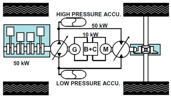
In the 21st century, with all the advances in engine and hydraulic systems for electronic control technology, the HFPE’s technical difficulties were resolved, giving HFPE research into new vitality. In the first few years of the 21st century, as shown in Figure 63, Volumtran proposed, based on a traditional engine power source for the electro–hydraulic hybrid system, a design reaching high speeds with low torque using 10 kW. The motor drives the load and uses a 50 kW hydraulic drive to drive the load at low speed and high torque. The system used the operation strategy of low-speed constant torque and high-speed constant power, which ensured the dynamic, comprehensive performance of the vehicle, thereby expanding the application prospects for HFPE.
There are some special working characteristics of HFPEs because of the differences between conventional engines and these engines. Among these characteristics, some make HFPEs better than conventional engines.
The HFPE contains three systems: an internal combustion system, a load system and a reset system. The internal combustion system usually applies to two-stroke engines because of no crank-link mechanism and a flywheel; the piston moves up and down in a cylinder and outputs hydraulic energy by driving the hydraulic load system [22][12]. The reset action can use an independent reset system or thermal energy produced by another cylinder. This engine can use multiple fuels because of its variable compressor, fuel injection and valve timing technology.
For HFPEs, the power piston movement law completely relies on the force loaded on the power piston. Therefore, it is necessary to finish the design and calculation processes in advance to make sure the piston movement rule is right. This is necessary for any prototype label. The biggest challenge is how to measure the piston position and control the piston movement rule precisely, because the piston position, as the real-time signal for the controller, could decide whether the controller works properly or not.
For a dual-piston, hydraulic free-piston engine, the working frequency is the piston’s harmonic frequency, so the range of working frequencies is relatively tight. The variable frequency output could be realized by changing the load and fuel-injection quantities. For single-piston and opposed-piston free-piston engines, more precise control could be realized because of the independent reset system; the working frequency could be controlled easily by adjusting when to release the compressed energy, and the range of output power is wider than for normal engines. Dutch Achten proposed the pulse pause modulation control method, and this method has been applied widely.
HFPEs once could not finish starting, depending on the motor, because of the absence of a crank-link mechanism and flywheel. In the middle of the 20th century, this engine could finish starting by compressed air—compressed air entered the spring back chamber by a channel. In this method the first cycle’s ignition could be realized easily, because it could provide a higher compression ratio; however, the heart of the matter was how to control the high-pressure air located in spring back chamber in order to provide enough time for exchanging gases. The free-piston generator could finish starting by changing its mode to a motor, whereas a hydraulic free-piston engine could use the hydraulic energy stored in a hydraulic cylinder to finish starting.
HFPEs are sensitive to in-cylinder operating parameters such as scavenging processes and mixed gas formation during operation [23][13]. In fact, the combustion process of HFPE is directly related to the formation of the mixture, which is directly affected by the scavenging process and the fuel injection process [24][14]. Further studies have found that the scavenging process and the fuel injection process are related to the kinetic parameters of the cycle of a given HFPE. Once a cycle of combustion fluctuates, it will seriously affect the next cycle’s scavenging and fuel injection process.
An HFPE’s balance has a certain impact on its operation, although the opposing-piston HFPE can be self-balancing, but other forms of HFPE have had vibration problems. Generally, improving the balance is a fast, reasonable way to achieve system balance [25][15]. In addition, HFPEs are mainly challenged by the lifetimes of piston components. Flynn and others pointed out that, due to the HFPE’s instantaneous heat release, the cylinder pressure rises quickly and the piston acceleration is immense, so piston component failure is mainly via hydraulic piston wear and the destruction of the power piston ring [26][11].
3. The Research Status of HFPEs
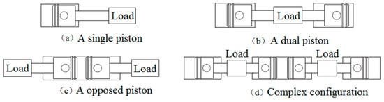
There are four types of free-piston engine according to piston arrangement form [12,24][16][14]: single piston, dual pistons, opposed pistons and four cylinders complex configuration as shown in Figure 104.
There are three components in this engine: the internal combustion system, the load system and the reset system. The load system and reset system can use one or two hydraulic cylinders. The biggest benefit of the single-piston, free-piston engine is its simple structure and controllability compared with other free-piston engines. The reset system can control resetting energy precisely, so the compression ratio and piston stroke are steerable, as is working frequency, which is controlled by adjusting the moment of release for reset energy.
The structure includes the internal combustion engine part, the hydraulic pump part and the compression part. The intermediate hydraulic piston is used to pump the high-pressure oil, in the hydraulic pump part; the internal combustion engine part is the two-stroke, reflow scavenging, hydraulic, auxiliary HEUI injection system diesel engine. Researchers who study CHIRON argue that there is a cyclical fluctuation in the combustion process of the internal combustion engine, and that some disturbances due to combustion boundary conditions will cause some cycles to fire; and there are problems in the operation of the free-piston engine—e.g., in a working cycle, the energy cannot be successfully pushed to the end of the piston. Since the hydraulic system uses a hydraulic system, the process has little effect on engine performance.
The single-piston HFPE is worse self-balanced than the dual-piston free-piston engine. The opposed-piston engine is the best self-balanced, so many researchers from the University of Minnesota made a complex-configuration, hydraulic free-piston engine by combining opposed pistons with dual pistons. This engine connects the air inlet piston and the outlet piston by a linkage; its hydraulic load settings are the same as those of the traditional opposed hydraulic free-piston engine, as shown in Figure 135. The issue about synchronism for the opposed free-piston engine could be solved by the dual pistons which neutralize the hydraulic force produced by the external rod piston [31][18].
from the University of Minnesota have studied control methods of opposed HFPEs and the practicability of this new type of combustion. In order to solve this problem, scholars proposed two projects: linear feedback control and nonlinear feedback control. The experimental results show the error could be controlled in a better range while using the nonlinear feedback controller which is deduced by physical model; the error is then about ±1mm. On the basis of this, researchers tried to apply HCCI to their HFPE, aiming at different piston displacement tracks.
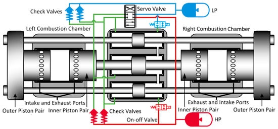
There is a kind of dual-piston HFPE which is shown in Figure 15[38]6[19]. This engine has two independent combustion chambers; the load systems are electromagnetic [39,40,41,42][20][21][22][23] and it uses hydraulic energy [43][24]. The output energies are electric and hydraulic energy. The difference between having dual pistons and a single piston is that there is no reset system for a dual-piston engine; the energy for the compression stroke on one side comes from the expansion stroke on the other side, and because of this, this engine is more compact and has higher power density.
However, there are still some problems puzzling engineers, such as how to control the stroke and compression ratio precisely, and what the movement discipline of the piston is [44][17]. Actually, these problems are affected by this engine’s special structure: even a tiny difference during combustion process could impact the compression process in another cylinder. Besides, this engine is very sensitive to load and cyclical fluctuations; a tiny difference in load and cyclical fluctuations may lead to misfiring. In order to solve these problems, some researchers used gear engagement and the multi-cylinder parallelism method, and they made some progress [45][25].
Dual-piston HFPEs are also the current focus of much free-piston engine research; some research institutions have put forward a different dual-piston design, and some prototypes have emerged. The development of a free-piston engine with dual-piston construction was performed by the Tampere TU in Finland [46][26]. The researchers who analyzed the test results found that the cylinder pressure cycle fluctuations (between 7.7 and 8.8 MPa), caused by the cycling of fuel consumption fluctuations, result in blow-by gas loss. Cylinder pressure fluctuation is the main factor that causes the piston stroke to change.
The power system can be used underwater and in space, and the original internal combustion engine was different. This engine, according to load requirements to adjust the dynamic output, removed the idle link. The power plant outputs power of 1–3 kW, and its work by-products are only water and oxygen. Hydrogen peroxide, as the catalyst, is decomposed into a high-temperature gas used to promote the piston component’s movement and direct output hydraulic energy.
This engine owns two independent pistons but just one combustion chamber—two pistons in one cylinder. The main feature is force balance. However, this engine’s pistons demand higher synchronism, so a synchronizing mechanism is usually applied in this engine [49][27], yet this makes it more complex. Research about opposed-piston, free-piston engines appealed to many people when the theory was just born (1925–1960), and this engine works via free-piston air compressor and free-piston generator [50,51,52][28][29][30].
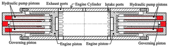
Professor Hibi of Toyohashi Polytechnic University in Japan began to study single-piston HFPEs in 1984 and took the lead in testing the performance. However, eventually Professor Hibi did not continue to study the single-piston HFPEs because of the control problem, but instead began to study the piston-type HFPEs [49][27]. Figure 197 shows the HFPE prototype model developed by Professor Hibi et al., which uses two sets of the same dynamic piston and hydraulic piston assembly. The hydraulic piston of each piston assembly is divided into three. Professor Hibi’s research team achieved operation of the piston-free-piston engine, and analysis of the cylinder pressure and piston displacement took place.
This engine has six cylinders without sparking plugs; each cylinder has four strokes; the fuel can be injected into each cylinder directly; the efficiency of this engine could be 39% while it is working under continuous and stable conditions; the literature has described this engine and offered test results. However, the engine has bad stability, and in order to improve its stability, Kevin Zaseck et al. applied pinion and rack to drive this engine [53][31]. This method would lead to an unbalanced situation even if the moment of crank inertia is very small. Researchers applied an adaptive algorithm to make sure the kinetic of crank could be changed along the set-points; actually, almost all disturbances were eliminated successfully when the rotational speed was 1000 RPM; in addition, this algorithm could handle the situation in which each cylinder had its own load [45,54][25][32].
The traditional electromechanical hybrid system can be replaced by these systems because of higher energy densities. These researchers developed a compact, portable and high efficiency free-piston compressor; they also established mathematical models and prototype test platforms at the same time. Based on the test platforms and math models, researchers could assess engine characteristics impacted by dynamic behavior of the hydraulic pistons [55,56][33][34]. The combustion chamber and compressor chamber are connected by two rigid pieces of diaphragm; the expand diaphragm in the combustion chamber works as a free-piston because of the flexible characteristic of the incompressible fluid.
In China, there are many universities and institutes that have studied HFPE; they include Tianjin University, Zhejiang University, Jilin University and the Beijing Institute of Technology. Zhejiang University and the Beijing Institute of Technology developed a dual-piston HFPE, and an opposed-piston HFPE and a single-piston HFPE, respectively.
The key laboratory of fluid transmission and control in Zhejiang University developed a first-generation dual-piston HFPE. Its engine is a two-stroke gas engine installed in an NF125FDI motorcycle; they have made some achievements in some areas, such as the starting process, energy distribution, dynamic characteristics research and prototype development. There are two strokes in one working cycle; each cylinder finishes a compressor stroke, expands the stroke, exhausts the stroke and inputs a stroke after two working cycles. This engine has low emissions and low fuel consumption [60][35].
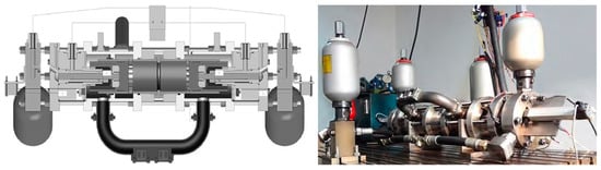
The Internal Combustion Engine Institute of Tianjin University proposed a project about opposed-pistons, two-stroke HFPEs, as shown in Figure 248. There are two pistons in one cylinder; these two pistons are driven by a hydraulic system and combustion gas in-cylinder without any mechanical joint. A gas exchange system applies the combination of uniflow scavenging and crank case scavenging. Besides, experts confirmed the relationships between piston movement characteristics and the coefficient of scavenging, strokes of the engine and the maximum allowed compressor; and they proposed a control method to command synchronization symmetry piston motion: combining the PI feedback control and feedforward control used to predict piston movement [61][36].
Due to this, researchers analyzed prototype stability by describing the buffer measures and position controlling measures [62][37]. There is one thing deserving of attention for saving the computing cost of control system. By lowering the computing cost of the control system, he unwittingly expanded the method to the application of the implicit system; the online computation speed of control system improved apparently after meeting constraints. In the future, this control strategy will have more reference values for evaluating model predictive control and the effect of the iterative reference governor algorithm [63,64][38][39].
Both of them applied diesel injection, uniflow scavenging and a cone valve. It could also be affected by diesel combustion and the response of the cone valve. The system has other disadvantages, such as the huge fluctuation of piston movement, being easy to stall, low power density and low efficiency of the cone valve [65,66,67][40][41][42]. After making sure this engine could operate steadily, the researchers discussed the characteristics of the starting process, circulative fluctuation and circulatory stability, and they have performed lots of experiments [68][43].
4. The Core Question and Research Progress
The free-piston engine has existed for over 100 years, but the research about the working process lags behind. Until recent years, the working process could not be established; modern methods such as modern analysis tools, simulation software and CFD enabled this change.
In order to achieve higher thermal efficiency and lower emissions, A.P. Kleemann et al. established the uniflow, scavenging, free-piston 3D calculation model in order to achieve higher thermal efficiency and lower emissions, as shown in Figure 279. The assumption of the researchers was that the discipline of heat release is related to gas exchange systems and fuel injection systems. In order to achieve better designs for inlet and outlet ports, they choose thermal efficiency and emission performance as optimizing indexes. The simulation showed that over 50% heat release, low soot and low NOx could be achieved via a higher compressor ratio, a higher EGR ratio and HCCI combustion mode.
R. Mikalsen reckoned that 0D could study the basic dynamic characteristics, but it is useless for in-cylinder flow movement and emission characteristics; besides, whether a thermodynamic model that applies to conventional engines is suitable for free-piston engines is unknown. He finally got the relationship between piston dynamics and in-cylinder flow. He used this model to explore the traits of piston movement, compression energy, ignition timing and ignition duration, and all of these affect the thermal efficiency. On the basis of previous research, R. Mikalsen tested emission characteristics, predicted piston control and finally made a comparison between a free-piston engine and a conventional engine [69,70,71,72][44][45][46][47].
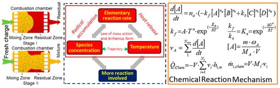
Besides, they thought that the air components in-cylinder and temperature affected the chemical reaction rate directly: the higher speed of reaction, the more atomic groups. The relationships among these factors are one positive feedback system, and this positive feedback system could be strengthened when in-cylinder temperature and atomic groups are specific, and this would increase the in-cylinder temperature eventually, as shown in Figure 2810. Some dynamic parameters such as volume and volume change rate, supported by piston trajectory, are the boundary conditions for chemical kinetics. When the temperature and pressure from chemical kinetics are input into the dynamic model again, these parameters can be applied via heat transfer model as the temperature and pressure condition at the same time [32][48].
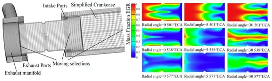
Wang yang et al. used Amesim to establish a 1D simulation model about an opposing-piston , two-stroke HFPE to research the coupling relationship between the gas exchange process and piston dynamics. They had established a CFD simulation model, as shown in Figure 2911. The research results showed that controlling exhaust flow could improve exchanging performance, and that optimizing the exhaust pulse could improve the volumetric efficiency.
The HFPE is a new type of engine, so researchers should start from an external dynamic model to explore the relationships between external dynamics and in-cylinder working processes. There are still many problems with those relationships and the control strategy.
The free-piston engine has an instinctive problem: stability. Finding out the factor which affects the stability is very important. Almost all relevant researchers use simulations and experiments to analyze external dynamic characteristics which affect the free-piston engine [73,74,75,76,77,78][49][50][51][52][53][54]. However, some studies reckon that piston velocity is better for better engine characteristics [79,80][55][56].
Since the control scheme relies on a given piston motion path and the given path is determined by the engine’s real-time load and compression ratio, it is difficult to give a more accurate tracking path in practice.(3)By modern control theory, the establishment of the relevant predictive control model [81,82][57][58] by controlling the input parameter variables for the piston components at the bottom of the positions to adjust, indirectly improves cycle stability. They focused on basic FPE analysis, clear actuators, control targets, operating parameters and other aspects of control. Then the researchers elaborated on the control problem, and pointed out that for the single-cylinder structure of the FPE, the control of fuel injection is the best way to accurately control the piston TDC; the piston BDC position can be controlled by the air cylinder. In this paper, simple PID control was used to realize the ideal tracking position of piston motion.
References
- Xia, B.Z.; Su, G.; Xie, H.B.; Yang, H.Y. Study on the Starting Process Driven by Accumulator of a Hydraulic Free Piston Engine. Appl. Mech. Mater. 2011, 121–126, 3092–3096.
- Heintz, R.P. Free Piston Engine-Pump Propulsion System. U.S. Patent 4,891,941, 9 January 1990.
- Ren, H.; Xie, H.; Yang, H.; Guo, J.F. Asymmetric vibration characteristics of two-cylinder four-stroke single-piston hydraulic free piston engine. J. Cent. South Univ. 2014, 21, 3762–3768.
- Peter, A.J.; Johan, P.J.; Potma, J.; Vael, G.E.M. Horsepower with Brains: The Design of the Chiron Free-Piston Engine; SAE Technical Paper 2000-01-2545; SAE International: Warrendale, PA, USA, 2000.
- Xia, B.Z.; Su, G.; Xie, H.B.; Yang, H.Y. Analysis on Energy Flow of a Bipropellant Powered Hydraulic Free Piston Engine. Appl. Mech. Mater. 2011, 121–126, 3102–3106.
- Bouthors, P.; Breting, O. Hydraulic Generator with Free-Piston Engine. U.S. Patent 4,415,313, 15 November 1983.
- Heintz, R.P. Free Piston Engine-Pump Propulsion System. U.S. Patent 4,891,941, 9 January 1990.
- Li, L.J.; Beachley, N.H. Design Feasibility of a Free Piston Internal Combustion Engine/Hydraulic Pump; SAE Technical Paper 880657; SAE International: Warrendale, PA, USA, 1998.
- Baruah, P.C. A Free-Piston Engine Hydraulic Pump for an Automotive Propulsion System; SAE Technical Paper 880658; SAE International: Warrendale, PA, USA, 1988.
- Beachley, N.H.; Fronczak, F.J. Design of a Free-Piston Engine-Pump; SAE Technical Paper 921740; SAE International: Warrendale, PA, USA, 1992.
- Yuan, S.H.; Wu, W. Simulation study of a two-stroke single piston hydraulic free-piston engine. In Proceedings of the 2008 Asia Simulation Conference-7th International Conference on System Simulation and Scientific Computing, Beijing, China, 10–12 October 2008; pp. 1244–1249.
- Uludogan, A.; Foster, D.E.; Reitz, R.D. Modeling the Effect of Engine Speed on the Combustion Process and Emissions in a DI Diesel Engine; SAE Technical Paper 962056; SAE International: Warrendale, PA, USA, 1996.
- Peter, A.J.; Johan, P.J.; Potma, J.; Vael, G.E.M. Horsepower with Brains: The Design of the Chiron Free-Piston Engine; SAE Technical Paper 2000-01-2545; SAE International: Warrendale, PA, USA, 2000.
- Braun, A.T.; Schweitzer, P.H. The Braun Linear Engine; SAE Technical Paper 730185; SAE International: Warrendale, PA, USA, 1973.
- Flynn, G., Jr. Observations on 25000h of free-piston-engine operation. SAE Trans. 1957, 65, 508–515.
- Tikkanen, S.; Lammila, M.; Herranen, M.; Vilenius, M. First Cycles of the Dual Hydraulic Free Piston Engine; SAE Technical Paper 2000-01-2546; SAE International: Warrendale, PA, USA, 2000.
- Li, K.; Zhang, C.; Sun, Z. Precise piston trajectory control for a free piston engine. Control. Eng. Pract. 2015, 34, 30–38.
- Zaseck, K.; Babajimopoulos, A.; Brusstar, M.; Filipi, Z.; Assanis, D.N. Design and modeling of a novel internal combustion engine with direct hydraulic power take-off. SAE Int. J. Altern. Powertrains 2013, 2, 204–216.
- Carter, D.; Wechner, E. The Free-Piston Power Pack: Sustainable Power for Hybrid Electric Vehicles; SAE Technical Paper 2003-01-3277; SAE International: Warrendale, PA, USA, 2003.
- Kim, Y.W.; Lim, J.; Jung, H.K. Starting mode analysis of flat-type linear generator for free-piston engine. Trans. Korean Inst. Electr. Eng. 2008, 57, 966–971.
- Christopher, M.; Sorin, P.; Nigel, N. Numerical Simulation of a Two-Stroke Linear Engine-Alternator Combination; SAE Technical Paper 1999-01-0921; SAE International: Warrendale, PA, USA, 1999.
- Jia, B.; Tian, G.; Feng, H.; Zuo, Z.; Roskilly, A.P. An experimental investigation into the starting process of free-piston engine generator. Appl. Energy 2015, 157, 798–804.
- Tikkanen, S.; Vilenius, M. Control of dual hydraulic free-piston engine. Int. J. Veh. Auton. Syst. 2006, 4, 3–23.
- Zaseck, K.; Kolmanovsky, I.; Brusstar, M. Adaptive control approach for cylinder balancing in a hydraulic linear engine. In Proceedings of the 2013 American Control Conference, Washington, DC, USA, 17–19 June 2013; pp. 2171–2176.
- Zaseck, K.M. Modeling and Control of Hydraulic Linear and Free-Piston Engines; US Environmental Protection Agency: Washington, DC, USA, 2013.
- Tikkanen, R.S.; Vilenius, P.M. Hydraulic free piston engine-the power unit of the future. In Proceedings of the JFPS International Symposium on Fluid Power, Tokyo, Japan, 22 October 1999; pp. 297–302.
- Hibi, A.; Ito, T. Fundamental test results of a hydraulic free-piston internal combustion engine. Proc. Inst. Mech. Eng. 2004, 218, 1149–1157.
- Fleming, J.D.; Bayer, R.J. Diesel Combustion Phenomena as Studied in Free Piston Gasifiers; SAE Technical Paper 630449; SAE International: Warrendale, PA, USA, 1963.
- Klotsch, P. Ford free-piston engine development. SAE Trans. 1959, 67, 373–378.
- London, A.L. Free-Piston and Turbine Compound Engine-Status of the Development. SAE Trans. 1954, 62, 426–436.
- Zaseck, K.; Kolmanovsky, I.; Brusstar, M. Extremum Seeking Algorithm to Optimize Fuel Injection in a Hydraulic Linear Engine. IFAC Proc. Vol. 2013, 46, 477–482.
- Zaseck, K.; Brusstar, M.; Kolmanovsky, I. Constraint enforcement of piston motion in a free-piston engine. In Proceedings of the 2014 American Control Conference, Portland, OR, USA, 4–6 June 2014; pp. 1487–1492.
- Willhite, J.A.; Yong, C.; Barth, E.J. The High Inertance Free Piston Engine Compressor-Part I: Dynamic Modeling. J. Dyn. Syst. Meas. Control. 2013, 135, 041003.
- Yong, C.; Barth E, J. The High Inertance Free Piston Engine Compressor-Part II: Design and Experimental Evaluation. J. Dyn. Syst. Meas. Control. 2013, 135, 041002-1.
- Xie, H.; Ren, H.; Yang, H.; Guo, J.F. Influence of Pressure Build-Up Time of Compression Chamber on Improving the Operation Frequency of a Single-Piston Hydraulic Free-Piston Engine. Adv. Mech. Eng. 2013, 5, 406807.
- Zhu, Y.; Wang, Y.; Zhen, X.; Guan, S.; Wang, J.; Wu, Y.; Chen, Y.; Yin, S. The control of an opposed hydraulic free piston engine. Appl. Energy 2014, 126, 213–220.
- Li, S.Y.; Yuan, Z.C.; Ma, J.Y. Study on the Motion Characteristics of a Hydraulic Free-Piston Engine. Adv. Mater. Res. 2014, 889, 390–393.
- Gong, X.; Zaseck, K.; Kolmanovsky, I.; Chen, H. Modeling and predictive control of free piston engine generator. In Proceedings of the 2015 American Control Conference (ACC), Chicago, IL, USA, 1–3 July 2015; pp. 4735–4740.
- Gong, X.; Zaseck, K.; Kolmanovsky, I.; Chen, H. Dual-loop Control of Free Piston Engine Generator. IFAC-Papers Online 2015, 48, 174–180.
- Zhao, Z.; Zhang, F.; Huang, Y.; Zhao, C.; Guo, F. An experimental study of the hydraulic free piston engine. Appl. Energy 2012, 99, 226–233.
- Wang, L.; Zhao, Z.; Yu, C.; Zhang, F.; Zhao, C. Energy and exergy analysis of hydraulic free-piston engines. Proc. Inst. Mech. Eng. Part. D J. Automob. Eng. 2019, 233, 524–530.
- Zhang, S.; Zhao, Z.; Zhao, C.; Zhang, F.; Wang, S. Cold starting characteristics analysis of hydraulic free piston engine. Energy 2017, 119, 6234–6242.
- Wu, W.; Hu, J.; Yuan, S. Semi-analytical modelling of a hydraulic free-piston engine. Appl. Energy 2014, 120, 75–84.
- Kleemann, A.P.; Dabadie, J.C.; Henriot, S. Computational Design Studies for a High-Efficiency and Low-Emissions Free Piston Engine Prototype; SAE Technical Paper; SAE International: Warrendale, PA, USA, 2004.
- Mikalsen, R.; Roskilly, A.P. A computational study of free-piston diesel engine combustion. Appl. Energy 2009, 86, 1136–1143.
- Mikalsen, R.; Roskilly, A.P. The control of a free-piston engine generator. Part 1: Fundamental analyses. Appl. Energy 2010, 87, 1273–1280.
- Mikalsen, R.; Roskilly, A.P. The control of a free-piston engine generator. Part 2: Engine dynamics and piston motion control. Appl. Energy 2010, 87, 1281–1287.
- Zhang, C.; Li, K.; Sun, Z. Modeling of piston trajectory-based HCCI combustion enabled by a free piston engine. Appl. Energy 2015, 139, 313–326.
- Hung, N.B.; Lim, O.T. A study of a two-stroke free piston linear engine using numerical analysis. J. Mech. Sci. Technol. 2014, 28, 1545–1557.
- Woo, Y.; Lee, Y.J. Free piston engine generator: Technology review and an experimental evaluation with hydrogen fuel. Int. J. Automot. Technol. 2014, 15, 229–235.
- Haoling, R.; Tianliang, L.; Hai-Bo, X.; Hua-Yong, Y. Stability research of the compression process of two-cylinder four-stroke single-piston hydraulic free piston engine. Proc. Inst. Mech. Eng. 2017, 231, 2902–2911.
- Wang, Q.; Dai, L.; Wu, K.; Bai, J.; He, Z. Study on the combustion process and work capacity of a micro free-piston engine. J. Mech. Sci. Technol. 2015, 29, 4993–5000.
- Yin, N.; Chang, S.; Xu, Z.; Lin, J. Exergy Analysis of Ideal Thermodynamic Cycle for the Four Stroke Free Piston Engine (FPE). Int. Energy J. 2014, 14, 199–208.
- Qin, Z.; Yuan, C.; Yuan, Y.; Huang, Y. Tribological characteristics of piston rings in a single-piston hydraulic free-piston engine. Ind. Lubr. Tribol. 2017, 69, 765–785.
- Kim, J.; Bae, C.; Kim, G. The operation characteristics of a liquefied petroleum gas (LPG) spark-ignition free piston engine. Fuel 2016, 183, 304–313.
- Chen, Q.; Ren, H.; Lin, T.; Miao, C.; Fu, S. Design and optimisation of cushioning structure of hydraulic free-piston engine. J. Eng. 2019, 2019, 129–135.
- Jia, B.; Zuo, Z.; Feng, H.; Tian, G.; Smallbone, A.; Roskilly, A. Effect of closed-loop controlled resonance based mechanism to start free piston engine generator: Simulation and test results. Appl. Energy 2016, 164, 532–539.
- Jia, B.; Smallbone, A.; Feng, H.; Tian, G.; Zuo, Z.; Roskilly, A. A fast response free-piston engine generator numerical model for control applications. Appl. Energy 2016, 162, 321–329.