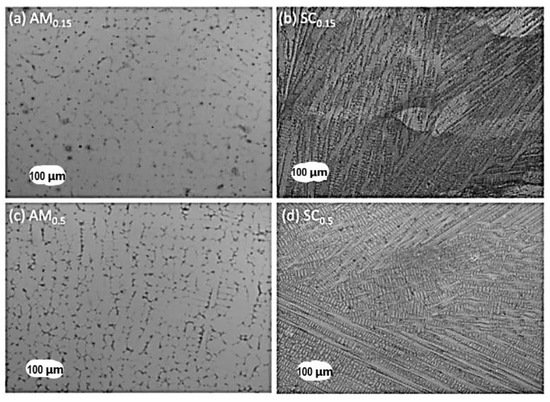
Microstructural phase evolution during melting and casting depends on the rate of cooling, the collective mobility of constituent elements, and binary constituent pairs. Parameters used in mechanical alloying and spark plasma sintering, the initial structure of binary alloy pairs, are some of the factors that influence phase evolution in powder-metallurgy-produced HEAs. Factors such as powder flowability, laser power, powder thickness and shape, scan spacing, and volumetric energy density (VED) all play important roles in determining the resulting microstructure in additive manufacturing technology. Large lattice distortion could hinder dislocation motion in HEAs, and this could influence the microstructure, especially at high temperatures, leading to improved mechanical properties in some HEAs. Mechanical properties of some HEAs can be influenced through solid solution hardening, precipitation hardening, grain boundary strengthening, and dislocation hardening. Despite the HEA system showing reliable potential engineering properties if commercialized, there is a need to examine the effects that processing routes have on the microstructure in relation to mechanical properties.
- high-entropy alloy
- powder metallurgy
- melting and casting
- microstructural evolution
- additive manufacturing
- solid solution strengthening
1. Introduction
The discovery and application of alloying and composite technology have made possible the achievement of various categories of materials that exhibit a wide range of properties. An example is a novel alloy system known as high-entropy alloys (HEAs). [1] defined HEAs, by composition, as alloys having at least five principal elements, wherein each has a concentration between 5 and 35 at.%. [2] also categorized HEAs based on elemental composition and configurational entropy.
Some categories of the HEAs studied are lanthanide HEAs [3[3][4],4], refractory HEAs (RHEAs) [6][5], and lightweight HEAs (LWHEAs) [7][6]. RHEAs are primarily developed for exceptionally high-temperature applications (up to 1400 °C), but with a disadvantage of high density. PGM-HEAs consist of precious elements (Au, Ag, Pt, Ir, Os, and Re), while LWHEAs are composed of low-density elements such as Li, Mg, Be, and Al.
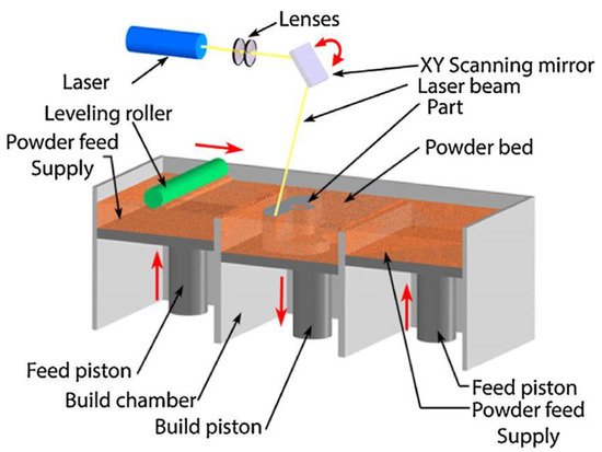
Over the past decade, material scientists have used several techniques in synthesizing HEAs, such as the melting and casting route, the powder metallurgy (PM) route, and additive manufacturing (AM) processing techniques. The PM process involving mechanical alloying (MA) and consolidation by spark plasma sintering (SPS) is usually used in attempts of achieving homogeneous microstructures in HEAs. In contrast, the AM fabrication route in recent years has received more attention in circumventing the flaws of other synthesis processes. The AM process is a flexible manufacturing technique with the capability of producing parts with complex geometries, finer microstructures, mass customization, and efficient material usage [11][7].
They are the high-entropy effect, sluggish diffusion effect, lattice distortion effect, and cocktail effect. Moreover, a fine precipitate and a controlled grain structure are usually formed as a result of the sluggish diffusion effect. The effect suggests that the pair distribution function directly relates to the distribution of the interatomic spacing on a local atomic level [15][8]. The properties of HEAs are known to be a result of the overall contributions of the constituent phases influenced by phase shape, phase distribution, and boundaries, as well as the properties of each phase [20][9].
There is no doubt that the basis of HEA design revolves around these so-called core effects. Hence, most HEAs studied have been derived from these basic principles [21,22,23][10][11][12]. Nevertheless, the validity of these core effects has been doubted by some researchers recently.
This makes the prediction of processing–structure relationships quite a challenge. The design approach adopted by most researchers does not follow a specific logic; rather, a number of these alloys are a result of a trial-and-error approach. Although attempts have been made to categorize these alloys according to the intended application, there still exists a multitude of alloys exhibiting a wide range of properties. This paper will also try to establish a structure–property relationship and link it to the processing route used.
2. Microstructural Evolution of HEAs Synthesized through the Melting and Casting Route
| HEA Composition | Processing Method | Observed Phase(s) | Microstructures and Comments | Reference |
|---|---|---|---|---|
| AlCoCrFeNi | Arc-melting | BCC | A dendritic structure is included. | [26,28][16][18] |
| AlTiVCr | Arc-melting | Single phase consisting of a B2 phase and a disordered BCC phase | The B2 phase is more stable than the disordered BCC phase. | [33][23] |
| AlCoFeNiTi | Arc-melting | BCC | A dendritic structure is included. | [34][24] |
| TiVZrNbHf | Arc-melting | Single-phase BCC | [35][25] | |
| AlCrFeNiMo0.2 | Vacuum Induction | BCC and B2 structure | The BCC phase is FeCrMo-rich, while the B2 phase is a NiAl-rich intermetallic compound. | [36][26] |
| NbCrMoTiAl0.5 | Arc-melting | Simple BCC | Mo segregates to the dendritic region. | [37][27] |
| NbCrMoTiVAl0.5Si0.3 | Cr, Ti, Al, and Si segregate to the interdendritic regions. | |||
| AlxCoFeNiSi (x > 0.3) | Arc-melting | BCC | [38][28] | |
| MoNbTaVW | Arc-melting | Single BCC | Dendritic and interdendritic regions are present due to constitutional segregation during solidification. | [39,40][29][30] |
| AlxCrFeMnNi0.5 | Arc-melting | BCC | [41][31] | |
| (x = 0.8–1.2) | ||||
| Nb25Mo25Ta25W25 | Arc-melting | BCC phase | There is no dendritic segregation. | [15][8] |
| Fe36Mn21Cr18Ni15Al10 | Arc-melting | Dual-phase 2 BCCs/B2 | The matrix phase (BCC) is rich in Fe and Cr. | [42][32] |
| The B2 phase is rich in Ni and Al. | ||||
| CoCrCuFeNi | Arc-melting | FCC | The interface morphology would grow in planar, cellular, and dendrite if the solidification rate is increased. | [18,43][33][34] |
| CoCrFeNiV0.5Cx | Arc-melting | FCC | A large number of M7C3-type interstitial carbides are formed at an annealing temperature of 700 °C and above. | [44][35] |
| (x = 0.01, 0.02, 0.03, and 0.04) | ||||
| Fe40Mn40Co10 |
3. Microstructural Evolution of HEAs Fabricated by Additive Manufacturing (AM)
| HEA Composition | Processing Method | Observed Phase(s) | Microstructures and Comments | Reference | |||||
|---|---|---|---|---|---|---|---|---|---|
| CoCrFeMnNi | Laser 3D printing | FCC (major) + BCC | An equiaxed-to-columnar transition structure was discovered in the melt pool. | [137][101] | |||||
| CoCrFeMnNi | Laser powder bed fusion (LPBF) | FCC + σ phase | Nanotwins were present in the printed sample. | [146][102] | |||||
| Mn segregates at the boundary of the weld pool due to its volatility. | |||||||||
| CoCrFeMnNi | Laser directed energy deposition | FCC solid solution | No phase transformation occurred | [147][103] | |||||
| Lattice strain and grain refinement occurred. | |||||||||
| AlCrFeCoNi | Selective electron beam melting (SEBM) | FCC + BCC | Phase evolution occurred during the preheating process | [134,135][97][98] | |||||
| AlCrFeCoMnNi | LPBF | BCC (B2, A2) | B2 (Ni-Al rich) and A2 (Fe-Cr rich) | [136][104] | |||||
| Due to liquid-phase spinodal decomposition and cubic nature of the HEA | |||||||||
| Al0.3CoCrFeNi | LPBF | Supersaturated FCC phase | Fine columnar grains were present due to rapid solidification and anisotropic heat removal. | [139][105] | |||||
| AlCoCrFeNiTi0.5 | Laser-engineered net shaping (LENS) | 2 BCC (B2, A2) | A fully equiaxed grain microstructure was exhibited rather than a columnar microstructure associated with alloys fabricated with AM. | [140][106] | |||||
| AlCrCuFeNi | LPBF | 2 BCC (B2, A2) | Unique columnar grains were present containing multiple ultrafine sub-grain structures. | [145][107] | |||||
| AlCrFeNiV | LPBF | FCC | Rapid cooling rate and solidification resulted in the formation of sub-grains in every columnar grain and L12 nano-phase. | [148][108] | |||||
| AlCrFe2Ni2 | LPBF | BCC | Columnar BCC of spinodal decomposed B2 and A2 structures was exhibited. | [149][109] | |||||
| Cr | |||||||||
| Cracks were present at the intergranular site. | |||||||||
| FeCoCrNi | LPBF | FCC | After annealing at 1373 K, columnar grains and equiaxial grains were found to co-exist. | [150][110] | |||||
| AlCoCrFeNi | Direct laser fabrication (DLF) | BCC (B2) | Intergranular needle-like and plate-like FCC phase precipitates and wall-shaped FCC phase precipitates were present along grain boundaries after aging at 800, 1000, and 1200 °C. | [151][111] | |||||
| MoNbTaW | Direct energy deposition (DED) | BCC | [152][112] | 10 | Vacuum induction | FCC | [ | ||
| Al0.5Cr1.0Mo1.0Nb | 45 | ] | [ | 36] | |||||
| 1.0Ta0.5 | SEBM | BCC | Two phases were present: TaMoNbCr and (TaMoNbCr)Al solid solutions. | [153][113] | CrMnFeCoNi | Arc-melting, Vacuum Induction | FCC | Precipitates of M23C6 and the σ phase exist following prolonged exposure at 700 °C. | [11, |
| CoCrCuFeNiAl | 46 | ] | [ | 7][ | LENS | 37] | |||
| BCC (B2, A2) | Dendritic grains were present. | [ | 154 | ,155][114][115] | AlxCoCrFeNi | Arc-melting | FCC | The FCC phase is transformed to the BCC phase with the presence of a transition duplex FCC/BCC region as Al increases. | [47][38] |
| An ordered interface transition region was present between the two phases. | (x = 0–0.65) | ||||||||
| AlCoCrFeNi2.1 | LENS | Ordered FCC (L12) + BCC | Co, Cr, and Fe stabilize L12. | [156][116] | CoCrFeNiTi0.3 | Arc-melting | FCC | A crystalline structure is present consisting of a mixture of a (Ni, Ti)-rich R phase and a (Cr, Fe)-rich σ phase within the FCC matrix. | [48][39] |
| L12 and BCC are rich in nickel. | Al0.5CoCrCu0.5FeNi | Arc-melting | FCC | The BCC phase will evolve from the FCC phase with an increase in the Al content. | |||||
| Fe38.5Mn20Co20Cr15Si | [ | 49 | ] | [40] | |||||
| FCC + BCC duplex phases will evolve at Al (0.5–1.5). | |||||||||
| 5Cu1.5 | LPBF | FCC | Deformation-induced phase transformation of γ (FCC) to ε (HCP) occurred in the vicinity of microcracks. | [157][117] | |||||
| CoCrFeNi | 3D extrusion printing | FCC | There was complex structural evolution, from loosely packed oxide particles in the green body to fully-annealed, metallic CoCrFeNi. | CoCrFeNiNb0.25 | Arc-melting | FCC | Lath-shaped FCC precipitates + nano-basket-weave microstructures are randomly distributed in the proeutectic FCC phase. | [50][41] | |
| AlxCoCrFeNiTiy | Arc-melting | FCC | The Al and Ti content strongly affects the phase and microstructure. | [51][42] | |||||
| [ | 158 | ] | [ | 118] | |||||
| AlCrFeMoVx (x = 0 to 1) | LENS | BCC | The high solubility of V offers a broad range of solid solution strengthening of a compositionally complex but structurally simple BC matrix. | [158][118] | |||||
| ZrTiVCrFeNi | LENS | C14 Laves phase (major) + α-Ti solid solution | The C14 Laves phase becomes stable on exposure to annealing and hydrogen influence. | [159][119] | Co1.5CrFeNi1.5Ti0.5Mox | Arc-melting | FCC | An interdendritic phase, (Ni, Ti)-rich phase and dendritic (Fe, Cr)-rich phase are present when x = 0, 0.1. | [52][43] |
| 6FeNiCoSiCrAlTi | Laser cladding | BCC | Equiaxed polygonal grains, discontinuous interdendritic segregation, and nano-precipitates are present. | [160][120] | (x = 0, 0.1) | ||||
| MoFeCrTiW | Laser cladding | BCC | Cellular crystals are formed on which dispersion precipitates exist. | [161][121] | Mn22.3Fe22.2Ni22.2Ge16.65Si16.65 | Arc-melting | FCC | Magneto-structural first-order phase transition is exhibited. | [53][44] |
| TiZrNbMoV | LENS | FCC (δTiHx-type) + BCC (NbH∼0.4–type) | αZr-rich precipitates are present, in addition to the phases formed. | [162][122] | AlCrFeMnNi | Arc-melting | BCC (B2) + FCC | The BCC phase is interdendritic and rich in Al + Ni. | |
| Al0.5FeCu0.7 | [ | 54 | ] | [45] | |||||
| NiCoCr | Laser cladding | FCC + BCC + Al phases | A laser rapid cooling rate facilitates the formation of a simple structure and prohibits the formation of undesired intermetallic compounds. | [163][123] | Ni30Co30Cr10Fe10Al18W2 | Arc-melting | FCC + BCC | Fine, regular, lamellar eutectic + coarse irregular eutectic hierarchical microstructures are present. | [ |
| TiZrNbHfTa | Laser metal deposition (LMD) | 55 | ] | BCC[46 | An equiaxed grain shape is present.] | ||||
| [ | 164 | ] | [ | 124] | Al0.5CrFeMnNi0.5 | Arc-melting | FCC + BCC | A dendritic region (higher Al and Cr) and an interdendritic region are present. | [56][47] |
| Al0.5CrMoNbTa0.5 | Electron beam melting (EBM) | BCC | Intermetallic phases C14, C36, C15, and 6H are present. | [165][125] | Precipitates (AlNi B2 compound) are present. | ||||
| Ni6Cr4WFe9Ti | LPBF | FCC | Tiny precipitates of an unknown phase are present. | [166][126] | AlxCoCrFeNi | Arc-melting | FCC + BCC | An AlNi-rich precipitate is formed. | |
| FeCoCrNiC0.05 | LPBF | FCC | Nano-scale Cr23C6-type carbides can precipitate under annealing conditions. | [57][48] | |||||
| [ | 167 | ] | [ | 127 | (x = 0.45–0.85) | ||||
| ] | Cr2Cu2FeNi2Mn2 | Arc-melting | FCC + BCC | A dendritic and interdendritic phase is present. | [58,59][49][50] | ||||
| Cr2Cu2NiMn2 | |||||||||
| CrCu2Fe2NiMn | Cu, Mn, Cr, and Fe are segregated in dendritic/interdendritic regions, while Ni is homogeneously distributed in the alloy. | ||||||||
| Cr2CuFe2NiMn | |||||||||
| Alx(CoCrFeMnNi)100−x | Arc-melting | FCC + BCC | An increase in Al turns the dendritic structure to a lamella-like structure, hence the transit from the FCC to the BCC phase. | [60][51] | |||||
| CoCrFeMnNiZrx (x = 0–0.3) | Arc-melting | FCC + BCC | Dendritic and interdendritic regions are present. | [61][52] | |||||
| The interdendritic region increases with an increase in the Zr content. | |||||||||
| AlCoCrCuxNiTi | Arc-melting | FCC + BCC | Dendritic (contains compound impurities) and chrysanthemum-shape dendrites are present. | [62][53] | |||||
| (x = 0.5–0.8) | Cu segregates in the interdendritic region. | ||||||||
| CoCuyFeNiTix | Arc-melting | 2 FCCs + BCC | FCC 1 is Cu rich, and FCC 2 is Co rich (x = 1/3, 3/7, and 3/5). | [63][54] | |||||
| The BCC phase is β Ti rich (x = 3/5). | |||||||||
| CoCrFeNiCuAl | Arc-melting | FCC + BCC | A cast-dendritic morphology is present. | [64,65][55][56] | |||||
| The BCC phase is an ordered one. | |||||||||
| of 2 FCC phases are present. | |||||||||
| Fe50-XMn30Co10Cr10BX | Arc-melting | FCC + BCC | The addition of boron promotes the formation of M2B-type borides (M = Cr, Fe). | [66][57] | |||||
| (x = 0, 0.3, 0.6, 1.7 wt%) | |||||||||
| AlCrCuFeMnNi | Vacuum Induction | 2 BCCs (B2 + A2) + FCC | The 2BCC phase is formed by spinodal decomposition, i.e., B2 (NiAl dendrite matrix) and A2 (Cr-Fe rich) embedded precipitate. | [67][58] | |||||
| Al0.5CoCrFeNi | Arc-melting, Vacuum Induction | FCC + BCC crystalline structures | The presence of the Al-Ni-rich phase decreases as the aging temperature increases and, hence, leads to an increase in the amount of Al-(Ni, Co, Cr, Fe). | [68,69][59][60] | |||||
| NbMoTaTi–(W, V) | Arc-melting | BCC + HCP—with W inclusion | The HEA with “V” shows a dendritic/cellular microstructure rich in Ti and V. | [70][61] | |||||
| BCC—with V inclusion | The HEA with “W” forms a Ti-rich HCP phase. | ||||||||
| Al0.5CrCuNiV | Arc-melting | FCC + 2 BCCs + B2 | A dendrite rich in Cr and V is present. | [71][62] | |||||
| The incorporation of Cu into the 2-BBC phase differentiates it from the B2 phase. | |||||||||
| AlCoCrFeNi2.1 | Vacuum Induction | Dual-phase FCC + BCC (B2) | - | [72][63] | |||||
| AlCrCuFeNi | Arc-melting | FCC + BCC | The content of Ni has a significant effect on the HEA microstructure. | [73,[6474]][65] |
4. Recommendations for Future Studies
Large differences in the melting temperatures of the constituent elements due to compositional complexity result in elemental segregation, dendritic structure, and residual stress in HEAs fabricated using the melting and casting route. To address these discrepancies, the rate of cooling, differences in the local atomic arrangement, and the varying elemental diffusivity must be taken into consideration in future studies. Faster cooling routes such as suction casting, injection casting, melt spinning, or splat cooling suppress the precipitation of the secondary phase and thereby form a predominantly stable single-phase structure. Hence, induction remelting can reduce microsegregation, reduce the inhomogeneity challenge, and refine the grain size.
Most of the studies on HEAs fabricated by MA are focused on varying the milling duration in achieving a homogeneous solid solution of the elements. However, since the parameters of the MA process are not independent of each other, it is imperative to know that other parameters such as milling speed, the BPR, grinding media, and the milling environment are given some attention in future studies. These other parameters also significantly influence the heat generated during milling and the diffusion of elements in the solid solution process. A lower sintering temperature (depends on the melting temperatures of constituent elements) should also be considered.
There is no adequate information to better understand how, where, and why voids and porosity were formed in most AM-fabricated materials. More attention is needed in this area as controlling their distribution or avoiding them is crucial and requires a better understanding; hence, these defects are undesirable in certain engineering applications. Therefore, there is a need for the development and standardization of economically viable and printable materials for engineering applications in the AM fabrication technique spectrum to complement its processing advantages. Urgent attention is needed in developing computer-aided design tools and predictive models of both the printing process and the post-printing material properties in future studies.
[200][128], and more researchers have used the combinatorial approach in processing multicomponent alloys, more attention is still needed on this method owing to the possibility of exploring composition space. Thus, observations suggest that proper selection of the chemical composition and an appropriate processing route combined with appropriate thermomechanical treatment may offer an opportunity to manipulate the strengthening mechanism to enhance HEAs’ mechanical properties. An optimal composition with required properties could be more efficient. Therefore, more research with modeling and simulations is required, in addition to computational tools and integrated computational material engineering available.
References
- Yeh, J.-W.; Chen, S.-K.; Lin, S.-J.; Gan, J.-Y.; Chin, T.-S.; Shun, T.-T.; Tsau, C.-H.; Chang, S.-Y. Nanostructured High-Entropy Alloys with Multiple Principal Elements: Novel Alloy Design Concepts and Outcomes. Adv. Eng. Mater. 2004, 6, 299–303.
- Miracle, D.B.; Senkov, O.N. A critical review of high entropy alloys and related concepts. Acta Mater. 2017, 122, 448–511.
- Li, Z.; Zhao, S.; Ritchie, R.O.; Meyers, M.A. Mechanical properties of high-entropy alloys with emphasis on face-centered cubic alloys. Prog. Mater. Sci. 2019, 102, 296–345.
- Murty, B.S.; Yeh, J.W.; Ranganathan, S.; Bhattacharjee, P.P. 1-A brief history of alloys and the birth of high-entropy alloys. In High-Entropy Alloys, 2nd ed.; Murty, B.S., Yeh, J.W., Ranganathan, S., Bhattacharjee, P.P., Eds.; Elsevier: Amsterdam, The Netherlands, 2019; pp. 1–12.
- Wu, D.; Kusada, K.; Yamamoto, T.; Toriyama, T.; Matsumura, S.; Kawaguchi, S.; Kubota, Y.; Kitagawa, H. Platinum-Group-Metal High-Entropy-Alloy Nanoparticles. J. Am. Chem. Soc. 2020, 142, 13833–13838.
- Feng, R.; Gao, M.C.; Zhang, C.; Guo, W.; Poplawsky, J.D.; Zhang, F.; Hawk, J.A.; Neuefeind, J.C.; Ren, Y.; Liaw, P.K. Phase stability and transformation in a light-weight high-entropy alloy. Acta Mater. 2018, 146, 280–293.
- Pickering, E.J.; Muñoz-Moreno, R.; Stone, H.J.; Jones, N.G. Precipitation in the equiatomic high-entropy alloy CrMnFeCoNi. Scr. Mater. 2016, 113, 106–109.
- Zou, Y.; Maiti, S.; Steurer, W.; Spolenak, R. Size-dependent plasticity in an Nb25Mo25Ta25W25 refractory high-entropy alloy. Acta Mater. 2014, 65, 85–97.
- Yeh, J.-W. Alloy Design Strategies and Future Trends in High-Entropy Alloys. JOM 2013, 65.
- Ye, Y.; Wang, Q.; Lu, J.; Liu, C.; Yang, Y. High-entropy alloy: Challenges and prospects. Mater. Today 2016, 19, 349–362.
- Kottke, J.; Laurent-Brocq, M.; Fareed, A.; Gaertner, D.; Perrière, L.; Rogal, Ł.; Divinski, S.V.; Wilde, G. Tracer diffusion in the Ni–CoCrFeMn system: Transition from a dilute solid solution to a high entropy alloy. Scr. Mater. 2019, 159, 94–98.
- Sathiyamoorthi, P.; Basu, J.; Kashyap, S.; Pradeep, K.; Kottada, R.S. Thermal stability and grain boundary strengthening in ultrafine-grained CoCrFeNi high entropy alloy composite. Mater. Des. 2017, 134, 426–433.
- Santodonato, L.J.; Zhang, Y.; Feygenson, M.; Parish, C.M.; Gao, M.C.; Weber, R.J.; Neuefeind, J.C.; Tang, Z.; Liaw, P.K. Deviation from high-entropy configurations in the atomic distributions of a multi-principal-element alloy. Nat. Commun. 2015, 6, 5964.
- Khan, I.; Mostafa, A.; Aljarrah, M.; Essadiqi, E.; Medraj, M. Influence of cooling rate on microsegregation behavior of magnesium alloys. J. Mater. 2014, 2014, 657647.
- Ghiaasiaan, R.; Zeng, X.; Shankar, S. Controlled Diffusion Solidification (CDS) of Al-Zn-Mg-Cu (7050): Microstructure, heat treatment and mechanical properties. Mater. Sci. Eng. A 2014, 594, 260–277.
- Manzoni, A.; Daoud, H.; Völkl, R.; Glatzel, U.; Wanderka, N. Phase separation in equiatomic AlCoCrFeNi high-entropy alloy. Ultramicroscopy 2013, 132, 212–215.
- Wang, F.J.; Zhang, Y. Effect of Co addition on crystal structure and mechanical properties of Ti0.5CrFeNiAlCo high entropy alloy. Mater. Sci. Eng. A 2008, 496, 214–216.
- Tian, Q.; Zhang, G.; Yin, K.; Wang, W.; Cheng, W.; Wang, Y. The strengthening effects of relatively lightweight AlCoCrFeNi high entropy alloy. Mater. Charact. 2019, 151, 302–309.
- Lv, Y.; Hu, R.; Yao, Z.; Chen, J.; Xu, D.; Liu, Y.; Fan, X. Cooling rate effect on microstructure and mechanical properties of AlxCoCrFeNi high entropy alloys. Mater. Des. 2017, 132, 392–399.
- Verma, A.; Kumar, S.; Grant, P.; O’Reilly, K. Influence of cooling rate on the Fe intermetallic formation in an AA6063 Al alloy. J. Alloy. Compd. 2013, 555, 274–282.
- Wang, F.; Zhang, Y.; Chen, G.; Davies, H. Cooling rate and size effect on the microstructure and mechanical properties of AlCoCrFeNi high entropy alloy. J. Eng. Mater. Technol. 2009, 131, 034501.
- Kozieł, T. Estimation of cooling rates in suction casting and copper-mould casting processes. Arch. Metall. Mater. 2015, 60, 767–771.
- Qiu, Y.; Hu, Y.; Taylor, A.; Styles, M.; Marceau, R.; Ceguerra, A.; Gibson, M.; Liu, Z.; Fraser, H.; Birbilis, N. A lightweight single-phase AlTiVCr compositionally complex alloy. Acta Mater. 2017, 123, 115–124.
- Wang, X.; Xie, H.; Jia, L.; Lu, Z.L. Effect of Ti, Al and Cu Addition on Structural Evolution and Phase Constitution of FeCoNi System Equimolar Alloys. Mater. Sci. Forum 2012, 724, 335–338.
- Sobol’, O.; Andreev, A.; Gorban’, V.; Krapivka, N.; Stolbovoi, V.; Serdyuk, I.; Fil’chikov, V. Reproducibility of the single-phase structural state of the multielement high-entropy Ti-V-Zr-Nb-Hf system and related superhard nitrides formed by the vacuum-arc method. Tech. Phys. Lett. 2012, 38, 616–619.
- Dong, Y.; Jiang, L.; Jiang, H.; Lu, Y.; Wang, T.; Li, T. Effects of annealing treatment on microstructure and hardness of bulk AlCrFeNiMo0.2 eutectic high-entropy alloy. Mater. Des. 2015, 82, 91–97.
- Liu, C.M.; Wang, H.M.; Zhang, S.Q.; Tang, H.B.; Zhang, A.L. Microstructure and oxidation behavior of new refractory high entropy alloys. J. Alloy. Compd. 2014, 583, 162–169.
- Zhang, Y.; Zuo, T.; Cheng, Y.; Liaw, P.K. High-entropy Alloys with High Saturation Magnetization, Electrical Resistivity and Malleability. Sci. Rep. 2013, 3, 1455.
- Senkov, O.N.; Wilks, G.B.; Miracle, D.B.; Chuang, C.P.; Liaw, P.K. Refractory high-entropy alloys. Intermetallics 2010, 18, 1758–1765.
- Senkov, O.N.; Wilks, G.; Scott, J.; Miracle, D.B. Mechanical properties of Nb25Mo25Ta25W25 and V20Nb20Mo20Ta20W20 refractory high entropy alloys. Intermetallics 2011, 19, 698–706.
- Tsai, M.-H.; Tsai, K.-Y.; Tsai, C.-W.; Lee, C.; Juan, C.-C.; Yeh, J.-W. Criterion for sigma phase formation in Cr-and V-containing high-entropy alloys. Mater. Res. Lett. 2013, 1, 207–212.
- Shaysultanov, D.G.; Salishchev, G.A.; Ivanisenko, Y.V.; Zherebtsov, S.V.; Tikhonovsky, M.A.; Stepanov, N.D. Novel Fe36Mn21Cr18Ni15Al10 high entropy alloy with bcc/B2 dual-phase structure. J. Alloys Compd. 2017, 705, 756–763.
- Li, C.; Li, J.; Zhao, M.; Jiang, Q. Effect of alloying elements on microstructure and properties of multiprincipal elements high-entropy alloys. J. Alloys Compd. 2009, 475, 752–757.
- Cui, H.B.; Zheng, L.F.; Wang, J.Y. Microstructure Evolution and Corrosion Behavior of Directionally Solidified FeCoNiCrCu High Entropy Alloy. Appl. Mech. Mater. 2011, 66–68, 146–149.
- Ma, Y.; Liu, X.; Dong, W.; Li, R.; Zhang, Y.; Lu, Y.; Yu, P.; Li, G. Interstitial carbide synergistically strengthening high-entropy alloy CoCrFeNiV0.5Cx. Mater. Sci. Eng. A 2020, 792, 139802.
- Deng, Y.; Tasan, C.C.; Pradeep, K.G.; Springer, H.; Kostka, A.; Raabe, D. Design of a twinning-induced plasticity high entropy alloy. Acta Mater. 2015, 94, 124–133.
- Yao, M.J.; Pradeep, K.G.; Tasan, C.C.; Raabe, D. A novel, single phase, non-equiatomic FeMnNiCoCr high-entropy alloy with exceptional phase stability and tensile ductility. Scr. Mater. 2014, 72–73, 5–8.
- Tian, F.; Delczeg, L.; Chen, N.; Varga, L.K.; Shen, J.; Vitos, L. Structural stability of NiCoFeCrAl$ high-entropy alloy from ab initio theory. Phys. Rev. B 2013, 88, 085128.
- Shun, T.-T.; Chang, L.-Y.; Shiu, M.-H. Microstructures and mechanical properties of multiprincipal component CoCrFeNiTix alloys. Mater. Sci. Eng. A 2012, 556, 170–174.
- Li, B.-y.; Peng, K.; Hu, A.-p.; Zhou, L.-p.; Zhu, J.-j.; Li, D.-y. Structure and properties of FeCoNiCrCu0.5Alx high-entropy alloy. Trans. Nonferrous Met. Soc. China 2013, 23, 735–741.
- He, F.; Wang, Z.; Niu, S.; Wu, Q.; Li, J.; Wang, J.; Liu, C.T.; Dang, Y. Strengthening the CoCrFeNiNb0.25 high entropy alloy by FCC precipitate. J. Alloys Compd. 2016, 667, 53–57.
- Chuang, M.-H.; Tsai, M.-H.; Wang, W.-R.; Lin, S.-J.; Yeh, J.-W. Microstructure and wear behavior of AlxCo1.5CrFeNi1.5Tiy high-entropy alloys. Acta Mater. 2011, 59, 6308–6317.
- Chou, Y.L.; Yeh, J.W.; Shih, H.C. The effect of molybdenum on the corrosion behaviour of the high-entropy alloys Co1.5CrFeNi1.5Ti0.5Mox in aqueous environments. Corros. Sci. 2010, 52, 2571–2581.
- Law, J.Y.; Moreno-Ramírez, L.M.; Díaz-García, Á.; Martín-Cid, A.; Kobayashi, S.; Kawaguchi, S.; Nakamura, T.; Franco, V. MnFeNiGeSi high-entropy alloy with large magnetocaloric effect. J. Alloys Compd. 2021, 855, 157424.
- Masemola, K.; Popoola, P.; Malatji, N. The effect of annealing temperature on the microstructure, mechanical and electrochemical properties of arc-melted AlCrFeMnNi equi-atomic High entropy alloy. J. Mater. Res. Technol. 2020, 9, 5241–5251.
- Wu, Q.; Wang, Z.; Zheng, T.; Chen, D.; Yang, Z.; Li, J.; Kai, J.-j.; Wang, J. A casting eutectic high entropy alloy with superior strength-ductility combination. Mater. Lett. 2019, 253, 268–271.
- Chen, S.-T.; Tang, W.-Y.; Kuo, Y.-F.; Chen, S.-Y.; Tsau, C.-H.; Shun, T.-T.; Yeh, J.-W. Microstructure and properties of age-hardenable AlxCrFe1.5MnNi0.5 alloys. Mater. Sci. Eng. A 2010, 527, 5818–5825.
- Kao, Y.-F.; Chen, S.-K.; Chen, T.-J.; Chu, P.-C.; Yeh, J.-W.; Lin, S.-J. Electrical, magnetic, and Hall properties of AlxCoCrFeNi high-entropy alloys. J. Alloy. Compd. 2011, 509, 1607–1614.
- Ren, B.; Liu, Z.; Li, D.; Shi, L.; Cai, B.; Wang, M. Effect of elemental interaction on microstructure of CuCrFeNiMn high entropy alloy system. J. Alloy. Compd. 2010, 493, 148–153.
- Ren, B.; Liu, Z.; Cai, B.; Wang, M.; Shi, L. Aging behavior of a CuCr2Fe2NiMn high-entropy alloy. Mater. Des. 2012, 33, 121–126.
- He, J.Y.; Liu, W.H.; Wang, H.; Wu, Y.; Liu, X.J.; Nieh, T.G.; Lu, Z.P. Effects of Al addition on structural evolution and tensile properties of the FeCoNiCrMn high-entropy alloy system. Acta Mater. 2014, 62, 105–113.
- Pauzi, S.S.M.; Darham, W.; Ramli, R.; Harun, M.; Talari, M.K. Effect of Zr Addition on Microstructure and Properties of FeCrNiMnCoZr x and Al 0.5 FeCrNiMnCoZr x High Entropy Alloys. Trans. Indian Inst. Met. 2013, 66, 305–308.
- Wang, C.W.; Mo, Z.Q.; Tang, J.J. The Study about Microstructure Characterization of AlCoCrTiNiCu_x High Entropy Alloy System with Multi-principal element. Adv. Mater. Res. 2012, 399, 3–7.
- Mishra, A.K.; Samal, S.; Biswas, K. Solidification behaviour of Ti–Cu–Fe–Co–Ni high entropy alloys. Trans. Indian Inst. Met. 2012, 65, 725–730.
- Zhang, K.B.; Fu, Z.Y.; Zhang, J.Y.; Shi, J.; Wang, W.M.; Wang, H.; Wang, Y.C.; Zhang, Q.J. Annealing on the structure and properties evolution of the CoCrFeNiCuAl high-entropy alloy. J. Alloys Compd. 2010, 502, 295–299.
- Wen, L.H.; Kou, H.C.; Li, J.S.; Chang, H.; Xue, X.Y.; Zhou, L. Effect of aging temperature on microstructure and properties of AlCoCrCuFeNi high-entropy alloy. Intermetallics 2009, 17, 266–269.
- Aguilar-Hurtado, J.Y.; Vargas-Uscategui, A.; Zambrano-Mera, D.; Palma-Hillerns, R. The effect of boron content on the microstructure and mechanical properties of Fe50-XMn30Co10Cr10BX (x = 0, 0.3, 0.6 and 1.7 wt%) multi-component alloys prepared by arc-melting. Mater. Sci. Eng. A 2019, 748, 244–252.
- Soare, V.; Mitrica, D.; Constantin, I.; Popescu, G.; Csaki, I.; Tarcolea, M.; Carcea, I. The mechanical and corrosion behaviors of as-cast and re-melted AlCrCuFeMnNi multi-component high-entropy alloy. Metall. Mater. Trans. A 2015, 46, 1468–1473.
- Guo, T.; Li, J.; Wang, J.; Wang, W.Y.; Liu, Y.; Luo, X.; Kou, H.; Beaugnon, E. Microstructure and properties of bulk Al0.5CoCrFeNi high-entropy alloy by cold rolling and subsequent annealing. Mater. Sci. Eng. A 2018, 729, 141–148.
- Lin, C.-M.; Tsai, H.-L. Evolution of microstructure, hardness, and corrosion properties of high-entropy Al0.5CoCrFeNi alloy. Intermetallics 2011, 19, 288–294.
- McAlpine, S.W.; Logan, J.V.; Short, M.P. Predicting single phase stability and segregation in the NbMoTaTi–(W,V) high entropy alloy system with the vacancy exchange potential. Scr. Mater. 2021, 191, 29–33.
- Yi, J.; Tang, S.; Xu, M.; Yang, L.; Wang, L.; Zeng, L. A novel Al0.5CrCuNiV 3d transition metal high-entropy alloy: Phase analysis, microstructure and compressive properties. J. Alloys Compd. 2020, 846, 156466.
- Gao, X.; Lu, Y.; Zhang, B.; Liang, N.; Wu, G.; Sha, G.; Liu, J.; Zhao, Y. Microstructural origins of high strength and high ductility in an AlCoCrFeNi2.1 eutectic high-entropy alloy. Acta Mater. 2017, 141, 59–66.
- Jinhong, P.; Ye, P.; Hui, Z.; Lu, Z. Microstructure and properties of AlCrFeCuNix (0.6≤ x≤ 1.4) high-entropy alloys. Mater. Sci. Eng. A 2012, 534, 228–233.
- Anmin, L.; Zhang, X. Thermodynamic analysis of the simple microstructure of AlCrFeNiCu high-entropy alloy with multi-principal elements. Acta Metall. Sin. 2009, 22, 219–224.
- Qi, J.; Cheung, A.M.; Poon, S.J. High Entropy Alloys Mined From Binary Phase Diagrams. Sci. Rep. 2019, 9, 15501.
- Tsao, T.-K.; Yeh, A.-C. The Thermal Stability and Strength of Highly Alloyed Ni3Al. Mater. Trans. 2015, 56, 1905–1910.
- Matusiak, K.; Berent, K.; Marciszko, M.; Cieslak, J. The experimental and theoretical study on influence of Al and Cu contents on phase abundance changes in AlxCuyFeCrNiCo HEA system. J. Alloys Compd. 2019, 790, 837–846.
- Aizenshtein, M.; Strumza, E.; Brosh, E.; Hayun, S. Precipitation kinetics, microstructure, and equilibrium state of A2 and B2 phases in multicomponent Al2.75CoCrFeNi alloy. J. Mater. Sci. 2020, 55, 7016–7028.
- Leong, Z.; Wróbel, J.S.; Dudarev, S.L.; Goodall, R.; Todd, I.; Nguyen-Manh, D. The Effect of Electronic Structure on the Phases Present in High Entropy Alloys. Sci. Rep. 2017, 7, 39803.
- Wang, J.; Shang, S.-L.; Wang, Y.; Mei, Z.-G.; Liang, Y.-F.; Du, Y.; Liu, Z.-K. First-principles calculations of binary Al compounds: Enthalpies of formation and elastic properties. Calphad 2011, 35, 562–573.
- Vaidya, M.; Prasad, A.; Parakh, A.; Murty, B. Influence of sequence of elemental addition on phase evolution in nanocrystalline AlCoCrFeNi: Novel approach to alloy synthesis using mechanical alloying. Mater. Des. 2017, 126, 37–46.
- Das, S.K.; Horbach, J.; Voigtmann, T. Structural relaxation in a binary metallic melt: Molecular dynamics computer simulation of undercooled Al 80 Ni 20. Phys. Rev. B 2008, 78, 064208.
- Dong, Y.; Jiang, L.; Tang, Z.; Lu, Y.; Li, T. Effect of electromagnetic field on microstructure and properties of bulk AlCrFeNiMo 0.2 high-entropy alloy. J. Mater. Eng. Perform. 2015, 24, 4475–4481.
- Zheng, H.; Chen, R.; Qin, G.; Li, X.; Su, Y.; Ding, H.; Guo, J.; Fu, H. Phase separation of AlCoCrFeNi2. 1 eutectic high-entropy alloy during directional solidification and their effect on tensile properties. Intermetallics 2019, 113, 106569.
- Shun, T.-T.; Hung, W.-J. Effects of Cr Content on Microstructure and Mechanical Properties of AlCoCr x FeNi High-Entropy Alloy. Adv. Mater. Sci. Eng. 2018, 2018, 5826467.
- Chaudhary, V.; Gwalani, B.; Soni, V.; Ramanujan, R.V.; Banerjee, R. Influence of Cr Substitution and Temperature on Hierarchical Phase Decomposition in the AlCoFeNi High Entropy Alloy. Sci. Rep. 2018, 8, 15578.
- Tang, Z.; Gao, M.C.; Diao, H.; Yang, T.; Liu, J.; Zuo, T.; Zhang, Y.; Lu, Z.; Cheng, Y.; Zhang, Y.; et al. Aluminum Alloying Effects on Lattice Types, Microstructures, and Mechanical Behavior of High-Entropy Alloys Systems. JOM 2013, 65, 1848–1858.
- Mohanty, A.; Sampreeth, J.K.; Bembalge, O.; Hascoet, J.Y.; Marya, S.; Immanuel, R.J.; Panigrahi, S.K. High temperature oxidation study of direct laser deposited AlXCoCrFeNi (X=0.3,0.7) high entropy alloys. Surf. Coat. Technol. 2019, 380, 125028.
- Butler, T.M.; Weaver, M.L. Oxidation behavior of arc melted AlCoCrFeNi multi-component high-entropy alloys. J. Alloy. Compd. 2016, 674, 229–244.
- Ferrari, V.; Wolf, W.; Zepon, G.; Coury, F.; Kaufman, M.; Bolfarini, C.; Kiminami, C.; Botta, W. Effect of boron addition on the solidification sequence and microstructure of AlCoCrFeNi alloys. J. Alloys Compd. 2019, 775, 1235–1243.
- Guo, L.; Xiao, D.; Wu, W.; Ni, S.; Song, M. Effect of Fe on microstructure, phase evolution and mechanical properties of (AlCoCrFeNi) 100-xFex high entropy alloys processed by spark plasma sintering. Intermetallics 2018, 103, 1–11.
- Wang, W.-R.; Wang, W.-L.; Yeh, J.-W. Phases, microstructure and mechanical properties of AlxCoCrFeNi high-entropy alloys at elevated temperatures. J. Alloys Compd. 2014, 589, 143–152.
- Rogström, L.; Ullbrand, J.; Almer, J.; Hultman, L.; Jansson, B.; Odén, M. Strain evolution during spinodal decomposition of TiAlN thin films. Thin Solid Film. 2012, 520, 5542–5549.
- Kucza, W.; Dąbrowa, J.; Cieślak, G.; Berent, K.; Kulik, T.; Danielewski, M. Studies of “sluggish diffusion” effect in Co-Cr-Fe-Mn-Ni, Co-Cr-Fe-Ni and Co-Fe-Mn-Ni high entropy alloys; determination of tracer diffusivities by combinatorial approach. J. Alloy. Compd. 2018, 731, 920–928.
- Tsai, K.Y.; Tsai, M.H.; Yeh, J.W. Sluggish diffusion in Co–Cr–Fe–Mn–Ni high-entropy alloys. Acta Mater. 2013, 61, 4887–4897.
- Anand, G.; Goodall, R.; Freeman, C.L. Role of configurational entropy in body-centred cubic or face-centred cubic phase formation in high entropy alloys. Scr. Mater. 2016, 124, 90–94.
- Mo, Y.; Tian, Z.; Liu, R.; Hou, Z.; Wang, C. Structural evolution during crystallization of rapidly super-cooled copper melt. J. Non-Cryst. Solids 2015, 421, 14–19.
- Zhang, L.; Fan, J.; Liu, D.; Zhang, M.; Yu, P.; Jing, Q.; Ma, M.; Liaw, P.; Li, G.; Liu, R. The microstructural evolution and hardness of the equiatomic CoCrCuFeNi high-entropy alloy in the semi-solid state. J. Alloys Compd. 2018, 745, 75–83.
- Qin, G.; Wang, S.; Chen, R.; Gong, X.; Wang, L.; Su, Y.; Guo, J.; Fu, H. Microstructures and mechanical properties of Nb-alloyed CoCrCuFeNi high-entropy alloys. J. Mater. Sci. Technol. 2018, 34, 365–369.
- Hsu, C.-Y.; Yeh, J.-W.; Chen, S.-K.; Shun, T.-T. Wear resistance and high-temperature compression strength of Fcc CuCoNiCrAl 0.5 Fe alloy with boron addition. MMTA 2004, 35, 1465–1469.
- Gwalani, B.; Choudhuri, D.; Soni, V.; Ren, Y.; Styles, M.; Hwang, J.; Nam, S.; Ryu, H.; Hong, S.H.; Banerjee, R. Cu assisted stabilization and nucleation of L12 precipitates in Al0. 3CuFeCrNi2 fcc-based high entropy alloy. Acta Mater. 2017, 129, 170–182.
- Gwalani, B.; Gorsse, S.; Soni, V.; Carl, M.; Ley, N.; Smith, J.; Ayyagari, A.V.; Zheng, Y.; Young, M.; Mishra, R.S. Role of copper on L12 precipitation strengthened fcc based high entropy alloy. Materialia 2019, 6, 100282.
- Zhou, W.; Fu, L.; Liu, P.; Xu, X.; Chen, B.; Zhu, G.; Wang, X.; Shan, A.; Chen, M. Deformation stimulated precipitation of a single-phase CoCrFeMnNi high entropy alloy. Intermetallics 2017, 85, 90–97.
- Zhang, D.; Qiu, D.; Gibson, M.A.; Zheng, Y.; Fraser, H.L.; StJohn, D.H.; Easton, M.A. Additive manufacturing of ultrafine-grained high-strength titanium alloys. Nature 2019, 576, 91–95.
- Chen, Q.; Guillemot, G.; Gandin, C.-A.; Bellet, M. Three-dimensional finite element thermomechanical modeling of additive manufacturing by selective laser melting for ceramic materials. Addit. Manuf. 2017, 16, 124–137.
- Kuwabara, K.; Shiratori, H.; Fujieda, T.; Yamanaka, K.; Koizumi, Y.; Chiba, A. Mechanical and corrosion properties of AlCoCrFeNi high-entropy alloy fabricated with selective electron beam melting. Addit. Manuf. 2018, 23, 264–271.
- Fujieda, T.; Shiratori, H.; Kuwabara, K.; Kato, T.; Yamanaka, K.; Koizumi, Y.; Chiba, A. First demonstration of promising selective electron beam melting method for utilizing high-entropy alloys as engineering materials. Mater. Lett. 2015, 159, 12–15.
- Zhang, K.; Wang, H. Effects of Annealing Treatment on Phase Composition and Microstructure of CoCrFeNiTiAlx High-Entropy Alloys. Intermetallics 2012, 22, 24–32.
- Ji, W.; Fu, Z.; Wang, W.; Wang, H.; Zhang, J.; Wang, Y.; Zhang, F. Mechanical alloying synthesis and spark plasma sintering consolidation of CoCrFeNiAl high-entropy alloy. J. Alloy. Compd. 2014, 589, 61–66.
- Gao, X.; Lu, Y. Laser 3D printing of CoCrFeMnNi high-entropy alloy. Mater. Lett. 2019, 236, 77–80.
- Li, R.; Niu, P.; Yuan, T.; Cao, P.; Chen, C.; Zhou, K. Selective laser melting of an equiatomic CoCrFeMnNi high-entropy alloy: Processability, non-equilibrium microstructure and mechanical property. J. Alloys Compd. 2018, 746, 125–134.
- Tong, Z.; Liu, H.; Jiao, J.; Zhou, W.; Yang, Y.; Ren, X. Improving the strength and ductility of laser directed energy deposited CrMnFeCoNi high-entropy alloy by laser shock peening. Addit. Manuf. 2020, 35, 101417.
- Jung, H.Y.; Peter, N.J.; Gärtner, E.; Dehm, G.; Uhlenwinkel, V.; Jägle, E.A. Bulk nanostructured AlCoCrFeMnNi chemically complex alloy synthesized by laser-powder bed fusion. Addit. Manuf. 2020, 35, 101337.
- Peyrouzet, F.; Hachet, D.; Soulas, R.; Navone, C.; Godet, S.; Gorsse, S. Selective Laser Melting of Al0.3CoCrFeNi High-Entropy Alloy: Printability, Microstructure, and Mechanical Properties. JOM 2019, 71, 3443–3451.
- Guan, S.; Solberg, K.; Wan, D.; Berto, F.; Welo, T.; Yue, T.M.; Chan, K.C. Formation of fully equiaxed grain microstructure in additively manufactured AlCoCrFeNiTi0.5 high entropy alloy. Mater. Des. 2019, 184, 108202.
- Luo, S.; Gao, P.; Yu, H.; Yang, J.; Wang, Z.; Zeng, X. Selective laser melting of an equiatomic AlCrCuFeNi high-entropy alloy: Processability, non-equilibrium microstructure and mechanical behavior. J. Alloys Compd. 2019, 771, 387–397.
- Yao, H.; Tan, Z.; He, D.; Zhou, Z.; Zhou, Z.; Xue, Y.; Cui, L.; Chen, L.; Wang, G.; Yang, Y. High strength and ductility AlCrFeNiV high entropy alloy with hierarchically heterogeneous microstructure prepared by selective laser melting. J. Alloys Compd. 2020, 813, 152196.
- Vogiatzief, D.; Evirgen, A.; Gein, S.; Molina, V.R.; Weisheit, A.; Pedersen, M. Laser Powder Bed Fusion and Heat Treatment of an AlCrFe2Ni2 High Entropy Alloy. Front. Mater. 2020, 7.
- Lin, D.; Xu, L.; Jing, H.; Han, Y.; Zhao, L.; Minami, F. Effects of annealing on the structure and mechanical properties of FeCoCrNi high-entropy alloy fabricated via selective laser melting. Addit. Manuf. 2020, 32, 101058.
- Wang, R.; Zhang, K.; Davies, C.; Wu, X. Evolution of microstructure, mechanical and corrosion properties of AlCoCrFeNi high-entropy alloy prepared by direct laser fabrication. J. Alloys Compd. 2017, 694, 971–981.
- Moorehead, M.; Bertsch, K.; Niezgoda, M.; Parkin, C.; Elbakhshwan, M.; Sridharan, K.; Zhang, C.; Thoma, D.; Couet, A. High-throughput synthesis of Mo-Nb-Ta-W high-entropy alloys via additive manufacturing. Mater. Des. 2020, 187, 108358.
- Popov, V.V.; Katz-Demyanetz, A.; Koptyug, A.; Bamberger, M. Selective electron beam melting of Al0.5CrMoNbTa0.5 high entropy alloys using elemental powder blend. Heliyon 2019, 5, e01188.
- Welk, B.A.; Williams, R.E.A.; Viswanathan, G.B.; Gibson, M.A.; Liaw, P.K.; Fraser, H.L. Nature of the interfaces between the constituent phases in the high entropy alloy CoCrCuFeNiAl. Ultramicroscopy 2013, 134, 193–199.
- Yue, T.; Xie, H.; Lin, X.; Yang, H.; Meng, G. Solidification behaviour in laser cladding of AlCoCrCuFeNi high-entropy alloy on magnesium substrates. J. Alloys Compd. 2014, 587, 588–593.
- Vikram, R.J.; Murty, B.S.; Fabijanic, D.; Suwas, S. Insights into micro-mechanical response and texture of the additively manufactured eutectic high entropy alloy AlCoCrFeNi2.1. J. Alloys Compd. 2020, 827, 154034.
- Thapliyal, S.; Nene, S.S.; Agrawal, P.; Wang, T.; Morphew, C.; Mishra, R.S.; McWilliams, B.A.; Cho, K.C. Damage-tolerant, corrosion-resistant high entropy alloy with high strength and ductility by laser powder bed fusion additive manufacturing. Addit. Manuf. 2020, 36, 101455.
- Kenel, C.; Casati, N.P.M.; Dunand, D.C. 3D ink-extrusion additive manufacturing of CoCrFeNi high-entropy alloy micro-lattices. Nat. Commun. 2019, 10, 904.
- Kunce, I.; Polanski, M.; Bystrzycki, J. Structure and hydrogen storage properties of a high entropy ZrTiVCrFeNi alloy synthesized using Laser Engineered Net Shaping (LENS). Int. J. Hydrogen Energy 2013, 38, 12180–12189.
- Zhang, H.; Pan, Y.; He, Y.; Jiao, H. Microstructure and properties of 6FeNiCoSiCrAlTi high-entropy alloy coating prepared by laser cladding. Appl. Surf. Sci. 2011, 257, 2259–2263.
- Zheng, B.; Liu, Q.B.; Zhang, L.Y. Microstructure and Properties of MoFeCrTiW High-Entropy Alloy Coating Prepared by Laser Cladding. Adv. Mater. Res. 2013, 820, 63–66.
- Kunce, I.; Polanski, M.; Bystrzycki, J. Microstructure and hydrogen storage properties of a TiZrNbMoV high entropy alloy synthesized using Laser Engineered Net Shaping (LENS). Int. J. Hydrogen Energy 2014, 39, 9904–9910.
- Ni, C.; Shi, Y.; Liu, J.; Huang, G. Characterization of Al0.5FeCu0.7NiCoCr high-entropy alloy coating on aluminum alloy by laser cladding. Opt. Laser Technol. 2018, 105, 257–263.
- Dobbelstein, H.; Gurevich, E.L.; George, E.P.; Ostendorf, A.; Laplanche, G. Laser metal deposition of a refractory TiZrNbHfTa high-entropy alloy. Addit. Manuf. 2018, 24, 386–390.
- Katz-Demyanetz, A.; Gorbachev, I.I.; Eshed, E.; Popov, V.V.; Popov, V.V.; Bamberger, M. High entropy Al0.5CrMoNbTa0.5 alloy: Additive manufacturing vs. casting vs. CALPHAD approval calculations. Mater. Charact. 2020, 167, 110505.
- Yang, X.; Zhou, Y.; Xi, S.; Chen, Z.; Wei, P.; He, C.; Li, T.; Gao, Y.; Wu, H. Additively manufactured fine grained Ni6Cr4WFe9Ti high entropy alloys with high strength and ductility. Mater. Sci. Eng. A 2019, 767, 138394.
- Zhou, R.; Liu, Y.; Liu, B.; Li, J.; Fang, Q. Precipitation behavior of selective laser melted FeCoCrNiC0.05 high entropy alloy. Intermetallics 2019, 106, 20–25.
- Welk, B.A.; Gibson, M.A.; Fraser, H.L. A combinatorial approach to the investigation of metal systems that form both bulk metallic glasses and high entropy alloys. JOM 2016, 68, 1021–1026.