By moving a commercial 2D LiDAR, 3D maps of the environment can be built, based on the data of a 2D LiDAR and its movements. Compared to a commercial 3D LiDAR, a moving 2D LiDAR is more economical. A series of problems need to be solved in order for a moving 2D LiDAR to perform better, among them, improving accuracy and real-time performance. In order to solve these problems, estimating the movements of a 2D LiDAR, and identifying and removing moving objects in the environment, are issues that should be studied.
- 3D laser scanning
- low-cost
- 2D LiDAR
- a moving 2D LiDAR
1. Introduction
Three-dimensional (3D) laser scanning technology, an advanced surveying and mapping method, has obvious advantages compared to traditional techniques. It combines high efficiency with data quality and accuracy. As the core sensor of 3D laser scanning technology, 3D LiDAR is widely used in many applications, such as terrain survey [1], architectural surveying and mapping [2], automatic driving [3], forest monitoring [4], and plant analysis [5].
However, for the moment, 3D LiDAR is generally expensive and is not consumer-grade yet. In comparison, 2D LiDAR is much more economical, and some 2D LiDARs are already consumer-grade [6]. As two major categories of commercial LiDAR, the differences between 2D LiDAR and 3D LiDAR are as follows: a 2D LiDAR is more economical than a 3D LiDAR, but it obtains less information, and it can only build 2D maps of the environment. On the other hand, a 3D LiDAR can build 3D maps of the environment; however, it is far more expensive than 2D LiDAR.
shows a comparison of the maps built by a 2D LiDAR and a 3D LiDAR, respectively. We investigated some commonly used commercial 2D LiDARs and 3D LiDARs; their manufacturers, models, performances, prices, and application fields are listed in
of
to provide readers with a more detailed understanding of them.
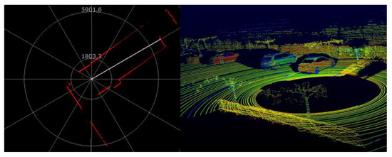
Figure 1.
By moving a commercial 2D LiDAR, 3D maps of the environment can be built based on the data of the 2D LiDAR and its movement [8][9][10][11]. Compared with a commercial 3D LiDAR, a moving 2D LiDAR is more economical, while its measurement performance is far inferior to that of the former. For applications that do not require excess measurement performance and require strict cost control (such as the 3D perception of the environment by a commercial home service robot), a moving 2D LiDAR may be useful. From this perspective, a moving 2D LiDAR is necessary and research-worthy.
By moving a commercial 2D LiDAR, 3D maps of the environment can be built based on the data of the 2D LiDAR and its movement [8,9,10,11]. Compared with a commercial 3D LiDAR, a moving 2D LiDAR is more economical, while its measurement performance is far inferior to that of the former. For applications that do not require excess measurement performance and require strict cost control (such as the 3D perception of the environment by a commercial home service robot), a moving 2D LiDAR may be useful. From this perspective, a moving 2D LiDAR is necessary and research-worthy.
It must be emphasized that a moving 2D LiDAR cannot completely replace a 3D LiDAR. In some applications, with high requirements on real-time performance and measurement ranges, such as automatic driving, a 3D LiDAR with better real-time performance and a longer measurement range is required, while a moving 2D LiDAR is not adequate. However, in other applications, such as the 3D mapping and navigation of an indoor robot, a moving 2D LiDAR can do the job. In these applications, a moving 2D LiDAR can partially replace a 3D LiDAR and provide a new choice for developers and engineers, which can reduce the costs, while the basic functions of 3D mapping are ensured.
In addition, a moving 2D LiDAR has the advantages of a flexible field of view and angular resolution. The field of view and angular resolution of a moving 2D LiDAR depend on the movement of the 2D LiDAR. Customizing scan parameters by moving LiDAR is not unique to 2D LiDAR. In [11][12][13][14][15][16][17][18][19], since the field of view and angular resolution of some 3D LiDARs are not suitable, researchers obtained the field of view and angular resolutions they wanted by moving these LiDARs.
In addition, a moving 2D LiDAR has the advantages of a flexible field of view and angular resolution. The field of view and angular resolution of a moving 2D LiDAR depend on the movement of the 2D LiDAR. Customizing scan parameters by moving LiDAR is not unique to 2D LiDAR. In [11,12,13,14,15,16,17,18,19], since the field of view and angular resolution of some 3D LiDARs are not suitable, researchers obtained the field of view and angular resolutions they wanted by moving these LiDARs.
2. Overview of Principles
In
, a TOF 2D LiDAR collects two sets of data at positions 1 and 2 in a room, respectively. At each position, in the fan-shaped scanning area of the 2D LiDAR, its emitter emits a certain number of laser beams, some of which shoot out of the door or window of the room, and do not reflect back. The remaining light beams encounter the objects or walls in the room, and reflect back. Those laser beams are received by the receiver of the 2D LiDAR, from which sampling points can be calculated.
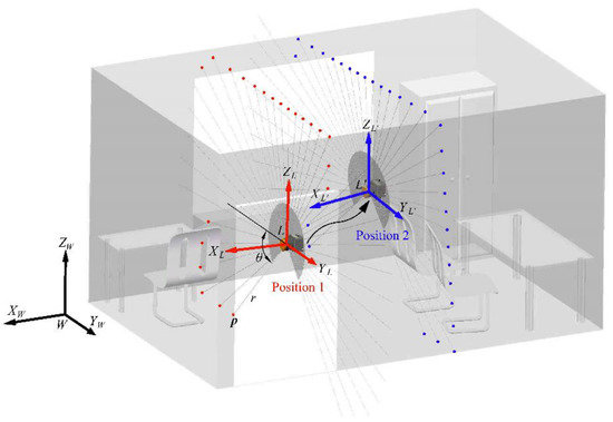
Figure 2.
The principle of a moving 2D LiDAR can be briefly summarized in one sentence, which is, 2D LiDAR collects sampling points at different positions, and these sampling points are converted to a global world coordinate frame. This process involves the conversion of the 3D coordinates of the sampling point between different coordinate frames. Here, we define three coordinate frames, namely, the coordinate frame of the 2D LiDAR (at position 1), which is denoted as
L
-
XLYLZL
; the coordinate frame of the 2D LiDAR at another position (position 2), which is denoted as
L′-XL′YL′ZL′
; the world coordinate frame
W-XWYWZW
, as shown in
.
3. Classification of the Prototypes
From a perspective of engineering, a moving 2D LiDAR can be built in many ways. In this section, we classify a moving 2D LiDAR by the most intuitive way, that is, the movement of 2D LiDAR.
For a moving 2D LiDAR, there are three common ways to move the 2D LiDAR, namely rotation, pitching, and push-broom. There is also literature on pitching as nodding [20][21][22]. In our paper, it is collectively referred to as pitching.
For a moving 2D LiDAR, there are three common ways to move the 2D LiDAR, namely rotation, pitching, and push-broom. There is also literature on pitching as nodding [20,38,68]. In our paper, it is collectively referred to as pitching.
3.1. A Rotating 2D LiDAR and a Pitching 2D LiDAR
There are some similarities between a rotating 2D LiDAR and a pitching 2D LiDAR. For both of them, 2D LiDAR is rotated by a motor. The motor changes the attitude of the 2D LiDAR, and, at the same time, another motor inside the 2D LiDAR rotates the emitter, which can emit the laser beam. In this way, the emitter can emit the laser beam into 3D space, and the scanning area of the 2D LiDAR is no longer limited to a 2D plane. There are two rotation axes involved here, one of which is the axis of rotation of the 2D LiDAR, the other is the axis of rotation of the emitter inside the 2D LiDAR. A rotating 2D LiDAR and a pitching 2D LiDAR are similar in principle. For both of them, the data collected by the 2D LiDAR and the angle position of the motor shaft are combined to calculate the 3D coordinates of the sampling points. According to the general principle of a moving 2D LiDAR analyzed in , for a rotating 2D LiDAR and a pitching 2D LiDAR, theTWL
in Equation (2) is a zero vector, andRWL
is the rotation matrix calculated according to the angle position of the motor shaft. The angle position of the motor shaft mentioned here is relative to the initial angle position. The initial angle position of the motor shaft should be recognized as a reference. In order to define the initial angle position of the motor shaft, an absolute encoder or a photoelectric switch is required. There are some points that need to be noted for both a rotating 2D LiDAR and a pitching 2D LiDAR: the optical center of the 2D LiDAR must coincide with its rotation axis, this depends on the mechanical accuracy; the ranging data of 2D LiDAR must be synchronized with its rotation/pitch angle, the accuracy of synchronization determines the accuracy of the rotation matrixRWL. In addition, the mechanical structure that rotate/pitch the 2D LiDAR should not obstruct the field of view of the 2D LiDAR [23].
. In addition, the mechanical structure that rotate/pitch the 2D LiDAR should not obstruct the field of view of the 2D LiDAR [69]. The main difference between a rotating 2D LiDAR and a pitching 2D LiDAR is that the rotation axis of a rotating 2D LiDAR coincides with the middle line of the scanning sector, while the rotation axis of a pitching 2D LiDAR is perpendicular to the middle line of the scanning sector and is coplanar with the scanning sector. The rotation angle of a rotating 2D LiDAR should to be no less than 180°, otherwise there will be blind areas in the field of view, while the rotation angle of a pitching 2D LiDAR can be flexibly adjusted according to the need of the field of view, as shown inFigure 3. From this point of view, a pitching 2D LiDAR can scan the front area faster than a rotating 2D LiDAR, and is thus more suitable for the area monitoring of mobile robots [23]. As mentioned in [20], for a rotating 2D LiDAR, when the 2D LiDAR is rotated around an axis parallel to the observation direction, it is suitable for environments such as tunnels or corridors. For a pitching 2D LiDAR, when the 2D LiDAR is rotated around an axis perpendicular to the observation direction, it is suitable for general ground robot applications, because in such applications, dense 3D point clouds that can show the terrain ahead are required.
. From this point of view, a pitching 2D LiDAR can scan the front area faster than a rotating 2D LiDAR, and is thus more suitable for the area monitoring of mobile robots [69]. As mentioned in [20], for a rotating 2D LiDAR, when the 2D LiDAR is rotated around an axis parallel to the observation direction, it is suitable for environments such as tunnels or corridors. For a pitching 2D LiDAR, when the 2D LiDAR is rotated around an axis perpendicular to the observation direction, it is suitable for general ground robot applications, because in such applications, dense 3D point clouds that can show the terrain ahead are required.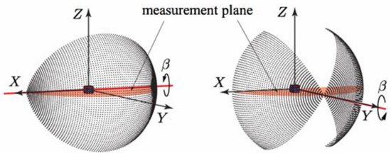
Figure 3. A pitching 2D LiDAR (left) and a rotating 2D LiDAR (right) [23].
Figure 5 shows the prototypes in [20][21][24][22][23].
shows the prototypes in [20,38,48,68,69].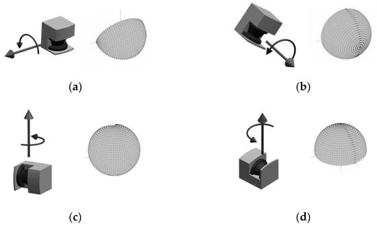
Figure 4.
a
b
c
d) a rotating 2D LiDAR whose rotation axis is vertical [24].
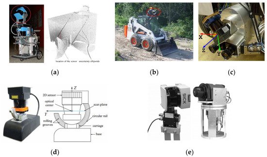
Figure 5.
a) A pitching 2D LiDAR mounted on a mobile platform. Left: the prototype in [22]; right: the pitching scanning example in [22]; (
b) the prototype in [21], a rotating 2D LiDAR (circled in red) which is mounted on a skid-steer loader; (
c
d) the prototype in [23], which is a pitching 2D LiDAR; (
e) the prototypes in [24]. Left: the first-generation prototype, which is a pitching 2D LiDAR whose rotation axis is vertical; right: the second-generation prototype, which is a rotating 2D LiDAR. Compared with the first-generation prototype, in the second-generation prototype a slip ring has been used, so that the 2D LiDAR can be rotated endlessly, without being blocked by cables.
3.2. A Push-Broom 2D LiDAR
Compared with a rotating 2D LiDAR and a pitching 2D LiDAR, the main feature of a push-broom 2D LiDAR is that there is no relative movement between the 2D LiDAR and the mobile platform on which it is carried, the 2D LiDAR is fixedly assembled on the mobile platform. The mobile platform mentioned here may be a vehicle [25][26][27][28], a backpack [16][29][30], a handheld pole [31][32], or a UAV (unmanned aerial vehicle) [33][34], as shown in
Compared with a rotating 2D LiDAR and a pitching 2D LiDAR, the main feature of a push-broom 2D LiDAR is that there is no relative movement between the 2D LiDAR and the mobile platform on which it is carried, the 2D LiDAR is fixedly assembled on the mobile platform. The mobile platform mentioned here may be a vehicle [36,37,70,71], a backpack [16,72,73], a handheld pole [74,75], or a UAV (unmanned aerial vehicle) [76,77], as shown in .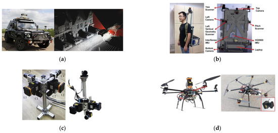
Figure 6.
a) A push-broom 2D LiDAR mounted on a vehicle. Left: the experimental platform in [25]; right: the push-broom scanning example in [28]; (
b) push-broom 2D LiDARs mounted on a backpack. Left: the prototype in [29]; right: the 3D model of the prototype in [30]; (
RWL
and the translation vectorTWL
) should be accurately known, so that the coordinates of the sampling points relative to the world coordinate frame can be accurately calculated by Equation (2). For a push-broom 2D LiDAR,RWL
andTWL
are determined by the movement of the mobile platform and the mechanical installation position of the 2D LiDAR on the mobile platform.3.3. Other Categories
In addition to the three common categories of a rotating 2D LiDAR, a pitching 2D LiDAR and a push-broom 2D LiDAR mentioned above, other categories can be found in some literatures.3.3.1. An Irregularly Rotating 2D LiDAR
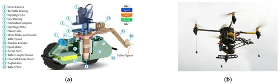
In [35], a 2D LiDAR is employed for 3D mapping of a tethered robot in steep terrain. The 2D LiDAR is fixedly mounted on the cable drum of the robot, when the cable drum is rotated by the motor, the 2D LiDAR is rotated too, and the position of the robot on the cliff changes accordingly. In this way, 2D LiDAR can be utilized to build 3D point cloud at different positions of the cliff.
In [36], the 2D LiDAR also rotates irregularly, and is carried by a UAV for aerial mapping. The 2D LiDAR is not rotated by a motor; it is rotated by the airflow generated by the four propellers of the UAV. The airflow blows the blades fixed together with the 2D LiDAR to rotate the 2D LiDAR around an axis.
In the cases of [35][36], because the rotation of the 2D LiDAR is non-periodic and irregular, so this category of a moving 2D LiDAR can be called an irregularly rotating 2D LiDAR.
Figure 7 shows the prototypes in [35][36].
3.3.2. An Obliquely Rotating 2D LiDAR
In [37][38][39][40], the 2D LiDAR is rotated periodically by a motor, unlike a rotating 2D LiDAR mentioned above, the 2D LiDAR is installed obliquely here, as the result of which, the distribution of the 3D point cloud is not a set of parallel lines, but a set of grid-like lines, as shown in
Figure 8. In this way, the missed detection of obstacles can be effectively avoided, especially when the resolution of the motor rotation angle is low and the point cloud is sparse [40]. In order to distinguish it from a rotating 2D LiDAR mentioned in
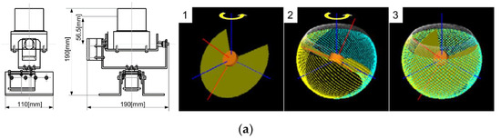
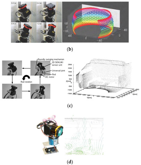
Figure 8.
a) The prototype in [37]; (
b) the prototype in [38]; (
c) the prototype in [39]; (
d) the prototype in [40].
3.3.3. An Irregularly Moving 2D LiDAR
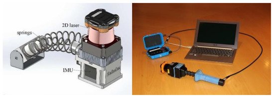
In [41][42], a handheld 3D mapping device, named Zebedee, was developed. A 2D LiDAR and an IMU (inertial measurement unit) was mounted on one end of the spring, and the other end of the spring was fixed on the handheld pole, as shown in
3.4. Extra 1: A Moving 3D LiDAR
By moving a commercial 2D LiDAR, 3D point clouds can be built; by moving a commercial 3D LiDAR, the field of view and resolution of the 3D LiDAR can be improved. In this subsection, we extra discuss related research on a moving 3D LiDAR.The terrestrial 3D laser scanners used for laser mapping of large-size objects [43][44] have wide field of views and they can build 3D point clouds, which are very dense, but they are usually very expensive and inconvenient to carry. The 3D LiDARs used for automatic driving [45] are relatively cheap, and their sizes and weights are more suitable for mobile platforms, but their vertical field of views and vertical resolutions are very limited [11][45]. These kinds of 3D LiDARs are designed for automatic driving, for this application, their vertical field of views and vertical resolutions are adequate. However, in some applications, dense 3D point clouds with full view are required. So, these kinds of 3D LiDARs cannot be used in these applications directly.
The terrestrial 3D laser scanners used for laser mapping of large-size objects [82,83] have wide field of views and they can build 3D point clouds, which are very dense, but they are usually very expensive and inconvenient to carry. The 3D LiDARs used for automatic driving [84] are relatively cheap, and their sizes and weights are more suitable for mobile platforms, but their vertical field of views and vertical resolutions are very limited [11,84]. These kinds of 3D LiDARs are designed for automatic driving, for this application, their vertical field of views and vertical resolutions are adequate. However, in some applications, dense 3D point clouds with full view are required. So, these kinds of 3D LiDARs cannot be used in these applications directly. In some research, this problem was solved by moving a 3D LiDAR, so that a 3D LiDAR with a limited vertical field of view and vertical resolution can build a 3D point cloud with a wider vertical field of view and a higher vertical resolution. Similar to a moving 2D LiDAR, the main ways to move a 3D LiDAR are rotation, pitching, and push-broom. The principle is also similar. A rotating 3D LiDAR and a pitching 3D LiDAR build 3D point clouds by combining the data of the 3D LiDAR and the angle position of the motor shaft. A push-broom 3D LiDAR builds 3D point clouds by combining the data of the 3D LiDAR and the position and attitude of the mobile platform. In order to make up for the deficiency of the vertical field of view and vertical resolution of the 3D LiDAR, in a push-broom 3D LiDAR, the 3D LiDAR is usually mounted obliquely rather than horizontally. Some representative application cases of a rotating 3D LiDAR, a pitching 3D LiDAR, and a push-broom 3D LiDAR are listed as follows.In terms of a rotating 3D LiDAR and a pitching 3D LiDAR, a 16-line 3D LiDAR Velodyne VLP-16 (Puck) is rotated by a motor to build dense 3D point clouds quickly in [12]. Compared with a rotating 2D LiDAR and a pitching 2D LiDAR, it needs less time to build a 3D point cloud, for the sampling speed of a 3D LiDAR is usually much higher than that of a 2D LiDAR. In [13], a pitching 3D LiDAR is used for the autonomous navigation of an unmanned vehicle, the 3D LiDAR used in this prototype is also Velodyne VLP-16 (Puck), it is swung up and down by a servo motor. In [14], a pitching 64-line 3D LiDAR Velodyne HDL-64e is mounted on a four-wheeled robot for the 3D mapping of the underground mines. Since the 3D LiDAR used in this prototype is pretty heavy (the weight of Velodyne HDL-64e is nearly 15 kg), a worm is used to increase the motivation so that the 3D LiDAR can be swung easily. However, this complicated design will not only further increase the volume, weight and cost of the prototype, but also lead to transmission clearance. This deficiency has been mentioned at the end of this literature. In [11], a portable tilt mechanism is designed to rotate a 3D LiDAR VLP-16, in this literature the spatial distribution of the 3D point cloud is focused on. The further study of this issue is in [15]. Moreover, similar research was done in [46]; this literature also focuses on the spatial distribution of the 3D point cloud, the difference is that in this literature, a moving 2D LiDAR, rather than a moving 3D LiDAR is used.
In terms of a rotating 3D LiDAR and a pitching 3D LiDAR, a 16-line 3D LiDAR Velodyne VLP-16 (Puck) is rotated by a motor to build dense 3D point clouds quickly in [12]. Compared with a rotating 2D LiDAR and a pitching 2D LiDAR, it needs less time to build a 3D point cloud, for the sampling speed of a 3D LiDAR is usually much higher than that of a 2D LiDAR. In [13], a pitching 3D LiDAR is used for the autonomous navigation of an unmanned vehicle, the 3D LiDAR used in this prototype is also Velodyne VLP-16 (Puck), it is swung up and down by a servo motor. In [14], a pitching 64-line 3D LiDAR Velodyne HDL-64e is mounted on a four-wheeled robot for the 3D mapping of the underground mines. Since the 3D LiDAR used in this prototype is pretty heavy (the weight of Velodyne HDL-64e is nearly 15 kg), a worm is used to increase the motivation so that the 3D LiDAR can be swung easily. However, this complicated design will not only further increase the volume, weight and cost of the prototype, but also lead to transmission clearance. This deficiency has been mentioned at the end of this literature. In [11], a portable tilt mechanism is designed to rotate a 3D LiDAR VLP-16, in this literature the spatial distribution of the 3D point cloud is focused on. The further study of this issue is in [15]. Moreover, similar research was done in [85]; this literature also focuses on the spatial distribution of the 3D point cloud, the difference is that in this literature, a moving 2D LiDAR, rather than a moving 3D LiDAR is used. shows the prototypes in the above-mentioned literatures.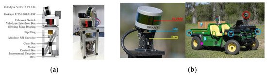
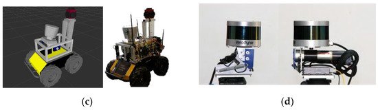
Figure 10.
a
b
c
d
In terms of a push-broom 3D LiDAR, A backpack-style 3D scanning device was developed by Wang [16][17][18], it is equipped with two 16-line 3D LiDARs VLP-16, one of which is mounted horizontally, and the other is mounted obliquely, its oblique angle is 45°. The sampling points collected by these two 3D LiDARs are converted to a global world coordinate frame. This backpack-style 3D scanning device can be utilized for the global 3D mapping of a large-scale structured environment. Similarly, the prototype in [19] can also be used for the global 3D mapping of a large-scale structured environment, compared with Wang’s research, the difference is that in this prototype, a 32-line 3D LiDAR Velodyne HDL-32e is carried by a trolley, it is mounted obliquely and the angle between the 3D LiDAR and the ground is approximately 66°.
In terms of a push-broom 3D LiDAR, A backpack-style 3D scanning device was developed by Wang [16,17,18], it is equipped with two 16-line 3D LiDARs VLP-16, one of which is mounted horizontally, and the other is mounted obliquely, its oblique angle is 45°. The sampling points collected by these two 3D LiDARs are converted to a global world coordinate frame. This backpack-style 3D scanning device can be utilized for the global 3D mapping of a large-scale structured environment. Similarly, the prototype in [19] can also be used for the global 3D mapping of a large-scale structured environment, compared with Wang’s research, the difference is that in this prototype, a 32-line 3D LiDAR Velodyne HDL-32e is carried by a trolley, it is mounted obliquely and the angle between the 3D LiDAR and the ground is approximately 66°. shows the prototypes in the above-mentioned literatures.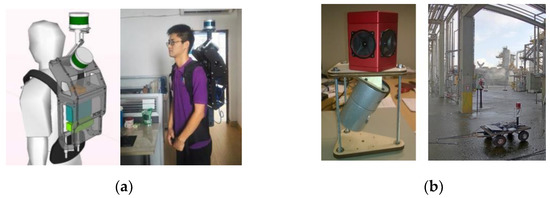
Figure 11.
b
3.5. Extra 2: DIY Low-Cost 3D LiDAR and a Rotating Mirror/Prism
A moving 2D LiDAR discussed in this paper is built by adding a movement to a commercial 2D LiDAR. Besides, in some research on low-cost 3D laser scanning technology, commercial LiDARs are not used. Instead, DIY (do-it-yourself) low-cost 3D LiDARs are built. The 3D LiDARs in these studies are fully DIY [47][48][49], or a mirror or prism is used to change the optical path of the laser beams [47][48][49][50]. Specifically, in [47], two prisms are utilized to project the laser beam in a large range in the vertical direction, as the result of which, a DIY 2D LiDAR is constructed. This DIY 2D LiDAR is rotated by a motor to collect the 3D sampling points of the environment. In [48], the emitter and receiver of the laser beams are rotated in a 2D plane; a mirror is rotated to change the optical path of the laser beams to add a scanning dimension of this prototype, allowing it to scan the environment in 3D. In [49], the emitter and receiver of the laser beams are fixedly mounted; a rotating prism is utilized to change the optical path of the laser beams in two dimensions to realize the 3D scanning function of the prototype. Similarly, in [50], a commercial 2D LiDAR is fixedly mounted, a rotating mirror is utilized to change the optical path of the laser beams. A 3D point cloud can be built according to the data of the 2D LiDAR and the rotation angle of the mirror.
A moving 2D LiDAR discussed in this paper is built by adding a movement to a commercial 2D LiDAR. Besides, in some research on low-cost 3D laser scanning technology, commercial LiDARs are not used. Instead, DIY (do-it-yourself) low-cost 3D LiDARs are built. The 3D LiDARs in these studies are fully DIY [86,87,88], or a mirror or prism is used to change the optical path of the laser beams [86,87,88,89]. Specifically, in [86], two prisms are utilized to project the laser beam in a large range in the vertical direction, as the result of which, a DIY 2D LiDAR is constructed. This DIY 2D LiDAR is rotated by a motor to collect the 3D sampling points of the environment. In [87], the emitter and receiver of the laser beams are rotated in a 2D plane; a mirror is rotated to change the optical path of the laser beams to add a scanning dimension of this prototype, allowing it to scan the environment in 3D. In [88], the emitter and receiver of the laser beams are fixedly mounted; a rotating prism is utilized to change the optical path of the laser beams in two dimensions to realize the 3D scanning function of the prototype. Similarly, in [89], a commercial 2D LiDAR is fixedly mounted, a rotating mirror is utilized to change the optical path of the laser beams. A 3D point cloud can be built according to the data of the 2D LiDAR and the rotation angle of the mirror.
shows the prototypes in the above-mentioned literatures.
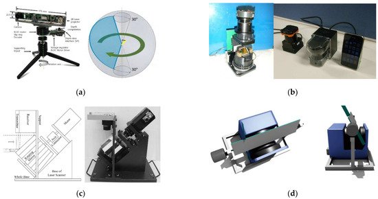
Figure 12. The prototypes in [47][48][49][50]. (
a) Left: the prototype in [47]; right: the field of view of this prototype; (
b) the prototypes in [48]. Left: the first-generation prototype; right: the second-generation prototype, it is placed between a commercial 2D LiDAR and a mobile phone to show its size; (
c) the prototype in [49]; (
d) the prototype in [50].
Compared with the method of adding a movement to a commercial 2D LiDAR, the method described in this subsection has greater technical difficulties. DIY LiDARs are certainly not as mature and reliable as commercial LiDARs in terms of technology, and the accuracy and stability of DIY LiDARs are not easily to be ensured. The way of changing the optical path through a mirror or a prism requires very high mechanical accuracy, while high mechanical accuracy requirement is not conducive to cost control of the prototype. In addition, stains and dust on the mirror or prism may block the propagation of the laser beam. In view of the above defects, the method described in this subsection is not the focus of our paper. In our paper, we focus on how to use commercial 2D LiDAR to build the 3D maps of the environment in low-cost. As mentioned in [23], it is a most feasible and common solution to apply a 2D LiDAR to the low-cost 3D mapping of the environment.
Compared with the method of adding a movement to a commercial 2D LiDAR, the method described in this subsection has greater technical difficulties. DIY LiDARs are certainly not as mature and reliable as commercial LiDARs in terms of technology, and the accuracy and stability of DIY LiDARs are not easily to be ensured. The way of changing the optical path through a mirror or a prism requires very high mechanical accuracy, while high mechanical accuracy requirement is not conducive to cost control of the prototype. In addition, stains and dust on the mirror or prism may block the propagation of the laser beam. In view of the above defects, the method described in this subsection is not the focus of our paper. In our paper, we focus on how to use commercial 2D LiDAR to build the 3D maps of the environment in low-cost. As mentioned in [69], it is a most feasible and common solution to apply a 2D LiDAR to the low-cost 3D mapping of the environment.