介电材料因其绝缘特性而被称为电绝缘材料。根据介质材料的不同,传统的介电电容器可分为三类。首先,有聚合物基双电电容器.这种电容器的介电材料主要是聚合物材料。第二,有陶瓷基介电电容器.这类电容器的介电材料包括多相陶瓷、玻璃陶瓷、陶瓷薄膜等。三是聚合物陶瓷复合介电电容器,以聚合物和陶瓷复合材料为存储介质。
Owing to their insulating properties, dielectric materials are known as electrically insulating materials. According to the different dielectric materials, traditional dielectric capacitors can be divided into three categories. Firstly, there are polymer-based dielectric capacitors. The dielectric materials of this type of capacitors are mainly polymer materials. Second, there are ceramic-based dielectric capacitors. The dielectric materials of such capacitors include multi-phase ceramics, glass ceramics, ceramic films, etc. Third is the polymer ceramic composite dielectric capacitors, using a variety of polymer and ceramic composite materials as storage medium.
- dielectric materials
- ferroelectric materials
- energy storage density
- electrocaloric effect
- low-temperature polarization
- GaN
1.电介质的分类 Classification of Dielectrics
1.1. Polymer-Based Dielectric Materials
The characteristics of polymers are high dielectric breakdown strength (>500 kV/cm) and low permittivity(1–20) [5]. There are many types of polymers and common polymer matrices include polyethylene, polyvinylidene fluoride, epoxy resin, and polyimide. The energy storage density of polymer membranes is relatively low due to the low permittivity.
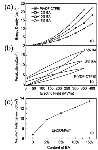
Binary and ternary copolymers exhibit more excellent dielectric and energy storage properties than single polymers. Z. Zhang et al. [6] prepared a vinylidene fluoride/trifluoroethylene/chlorotrifluoroethylene (PVDF/TrFE/CTFE) polymer, and its breakdown strength was greater than 500 kV/mm and energy storage density was more than 13 J/cm3. X. Zhou et al. [7] prepared vinylidene fluoride/chlorotrifluoroethylene (PVDF/CTFE) copolymer with a breakdown strength of 600 kV/mm and an energy storage density of up to 25 J/cm3. XZ Chen et al. [8] further added a bisamide compound (denoted as BA) to (PVDF/CTFE) and the prepared polymer had an energy storage density of 22.5 J/cm3 at an electric field strength of 400 kV/mm (Figure 1). In comparison with ceramic materials, plasticity is the major breakthrough of polymer-based dielectric materials. In practical applications, polymer-based dielectric materials can be bent into complex shapes according to the requirements of electronic devices, thereby reducing the volume of the device.
Figure 1. (a) Discharge energy density in (PVDF-CTFE) with different contents of cross-link agents. (b) Example of enhanced polarization in the cross-linked polymers shown by P–E loops at around 350 MV/m. (c). The maximum polarization of the copolymers at 280 MV/m. Reprinted with permission from [8]. Copyright 2011 WILEY-VCH Verlag GmbH & Co.
Although the energy storage density of the multi-polymer medium is high at low operating temperature, consequently, high-temperature functioning is challenging for different purposes such as aerospace and underground drilling. For example, the currently used commercial polymer material, the biaxially oriented polypropylene (BOPP), can only be used at temperatures below 105 °C. To cope with these problems, two strategies seem feasible: (i) polymer dielectric capacitors must be equipped with a cooling system to reduce the ambient temperature in high-temperature applications; (ii) polymers with a high glass transition temperature (Tg) are used in high-temperature capacitors to ensure the stability of dielectric properties at high temperatures. The former solution came with additional weight and volume, making the device heavy and difficult to achieve portability. The problem of the limited working temperature of the polymer dielectric material cannot be solved perfectly, which is an important research direction of polymer dielectric materials but that’s not in the scope of our current review.
1.2. Glass Ceramic-Based Dielectric Materials
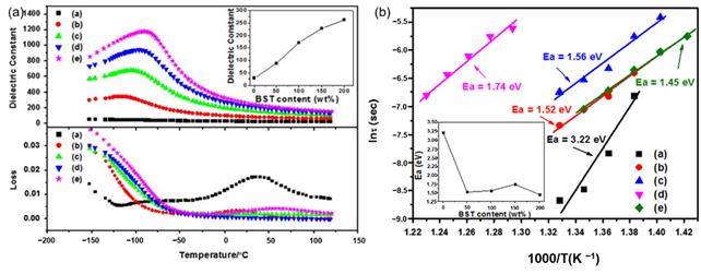
Glass ceramics is also one of the common dielectric materials, which is a composite material that combines structural glass phase and crystal through high-temperature melting, forming and heat treatment. Glass ceramics have high breakdown strength due to the glass phase. Among them, the size of the crystal phase normally ranges from the nanometer level to the micrometer level and the number of crystals can reach 50% to 90%. If the original composition is adjusted to ferroelectric crystal phases, ferroelectric glass ceramics can be obtained, which have both high permittivity and high breakdown strength. According to the different ferroelectric phases, there are two common ferroelectric glass ceramics: firstly, Titanate ferroelectric glass ceramics, with perovskite phase such as barium strontium titanate. J. Wang et al. reported on the modification of BaCO3-SrCO3-TiO2-Al2O3-SiO2 glass ceramics and its optimal energy storage density reached 2.81 J/cm3 (Figure 2). W. Zhang et al. [9] adopted microwave-processed BaXSr1-XTiO3-(Ba-B-AI-Si-O) glass ceramics to increase the breakdown strength of the dielectric material to 1486 kV/cm and the energy storage density was 2.8 J/cm3. Secondly, the ferroelectric phase is generally a niobate ferroelectric glass ceramic with a tungsten bronze structure, such as barium strontium niobite. Another common niobate glass ceramic is based on potassium niobate and sodium niobate as the ferroelectric phase and its energy storage density is about 2 J/cm3 [10]. The main glitch in the study of glass ceramics is interface polarization. The residual polarization of the material is large and the energy loss during the discharge is serious enough. In response to this problem, high breakdown strength glass can be added to the ceramic. The doped glass forms a liquid phase at the grain boundaries, which not only improves the breakdown strength of the ceramic, but also contributes to the sintering of the ceramic.
Figure 2. (a). Temperature dependence of permittivity and dissipation factor of (a) G-0 (b) G-50 (c) G-100 (d) G-150 and (e) G-200 (measured at 1 MHz). Inset: permittivity at room temperature of the samples. (b). Weibull plots of dielectric breakdown strength of (a) G-0 (b) G-50 (c) G-100 (d) G-150 and (e) G-200 (Ea: average dielectric breakdown strength). Inset: Ea of the samples. Reprinted with permission from [9]. Copyright 2013 Elsevier Ltd. and Techna Group S.r.l.
The applications of the ceramic membranes are also very extensive. The energy storage density of the films is larger due to its greater dielectric breakdown strength. For instance, the breakdown strength of the barium strontium titanate film can reach 1.0 MV/cm and the energy storage density is 11 J/cm3 [2]. Ceramic dielectrics have become one of the ideal third-generation pulse dielectric materials because of their characteristics of coordinated and controllable performance, wide operating temperature range and long cycle life.
1.3. Polymer Ceramic Composite Dielectric Materials
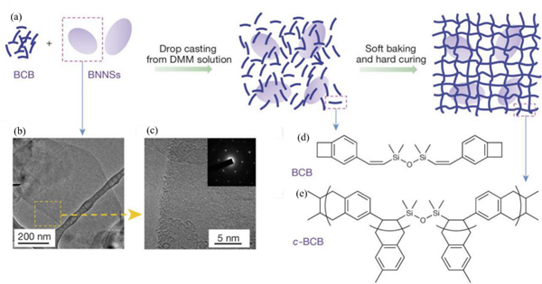
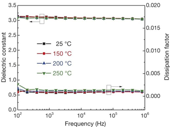
Polymer ceramic composite materials are also an important class of dielectric materials. Their design includes a synergistic effect, as the introduction of inorganic nanoparticles in the polymer matrix supplements the high permittivity of inorganic materials with the high breakdown strength of polymers. Due to the addition of inorganic particles on the nanometer scale, the interface area is increased, and the exchange coupling is promoted through the dipole interface layer, thereby obtaining higher polarization and dielectric response. N. Guo et al. [11] prepared isotactic polypropylene BaTiO3/TiO2 composite material by the in-situ metal complex polymerization method. Its permittivity was about 6.1, breakdown strength was about 400 MV/m and the energy storage density was 9.4 J/cm3. In 2015, Q. Li et al. [12] studied the composite materials of boron nitride nanosheets and polymers (Figure 3). Their dielectric properties are stable in a wide temperature and frequency range (Figure 4), and are internally stable below 250 °C the breakdown strength reached 403 MV/m and the energy storage density was 1.8 J/cm3. This finding showed that organic materials can also work at high temperatures after modification, which was the breakthrough in electronic devices.
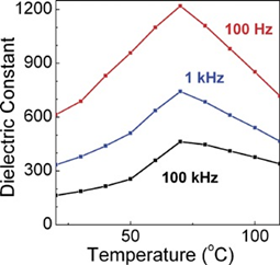
Another common composite materials are the conductive or semiconducting fillers, which on adding into the polymers, resulted as an increase in the permittivity of the dielectric material. Using this method, the permittivity of the composite material can be increased by tens or even hundreds of times. Y Zhang et al. [13] prepared the Zn-PVDF polymer composite material by flocculation method, which formed a 1.34 mm thick film by hot pressing, the permittivity and dissipation factor of this material at 1 kHz were 52 and 0.05, respectively. F. Fang et al. [14] prepared and studied PVDF/BaTiO3/Ag three-phase composite materials. When the filler content is 58%, the permittivity at 1 kHz was 160. ZM Dang et al. [15] prepared Ni-PVDF polymer composites using a relatively simple mixing and thermoforming method with a permittivity up to 400. M. Arbatti et al. [16] used copper-calcium titanate (CCTO) ceramics with similar properties as semiconductors as fillers into (PVDF-TrFE), forming of “sandwich” structure of hot-pressed composite materials with a permittivity of 610 at a frequency of 100 Hz (Figure 5).
Figure 3. Material preparation and structures. (a) Schematic of the preparation of c-BCB/BNNS films. (b, c) Transmission electron microscopy (TEM) images of BNNSs exfoliated from h-BN powders. Inset of c is an electron-diffraction pattern of BNNSs, showing its hexagonal symmetry. (d) Chemical structure of the BCB monomer. (e) The repeating unit of c-BCB. Reprinted with permission from [12]. Copyright 2015, Springer Nature.
Figure 4. Frequency dependence of the permittivity and dissipation factor of c-BCB/BNNS with 10 vol% of BNNSs at different temperatures. Error bars show standard deviation. Reprinted with permission from [12]. Copyright 2015, Springer Nature.
Figure 5. Permittivity at 100 Hz, 1 kHz and 100 kHz vs. temperature for hot-pressed composites. Reprinted with permission from [16]. Copyright 2007 WILEY-VCH Verlag GmbH & Co.
In the field of polymer ceramic composite materials, just by selecting a suitable polymer matrix and ceramic filler, the dielectric and energy storage properties of a material can be well adjusted. This selection makes them superior to the polymer matrix. At the same time, optimizing the interface between polymer and ceramic ensure their “compatibility” and the uniformity of the composite film is also an important prerequisite for obtaining high breakdown strength. At present, there are still many unsolved mysteries in this field such as: (i) The addition of ceramics increases the dielectric constant of the material, but the dielectric breakdown strength of the material is reduced. Balance maintenance between the two to achieve the optimization of energy storage performance is the most critical issue. (ii) The addition of ceramic materials deteriorates the mechanical properties of the polymer and affects the processing properties of the film. (iii) The interfacial effect of polymer and ceramics can be used to improve the energy storage performance of composite materials [17], but the essential characteristics of the interface still need to be further studied.
1.4. Ceramic-Based Dielectric Materials
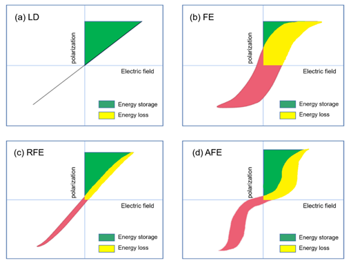
Extensive research has been done in ceramic dielectric materials by the scientific community. According to the different polarization curve properties, ceramic dielectrics can be divided into linear dielectrics ceramic, ferroelectric ceramic, relaxor ferroelectric ceramic, and antiferroelectric ceramic [18]. As shown in Figure 6, the four materials are introduced below.
Figure 6. Hysteresis and corresponding energy storage density for (a) linear dielectrics, (b) ferroelectrics, (c) relaxor ferroelectrics and (d) antiferroelectrics. The green area represents energy density and the red area refers to the energy loss.
Energy Storage Performance of Linear Dielectric
The polarization P of the linear dielectric material varies linearly with the electric field E (Figure 6a) and the permittivity does not change with the bias voltage field. The energy storage density of linear dielectric materials can be calculated by the following formula [19]:
where ε0 is the vacuum permittivity, εr is the relative permittivity of the material and E is the electric field strength. It can be seen from the formula that the energy storage density of the linear dielectric material is proportional to the square of the electric field strength.
SrTiO3 (STO) has a low Curie point and is paraelectric at room temperature, so it is generally classified as a linear dielectric ceramic. Research directions mainly include rare earth doping modification, preparation of new materials with high permittivity and low loss; adjustment of the preparation process, reduction of sintering temperature and increase of breakdown strength through the addition of glass. Z. Wang et al. [20] studied the effect of non-stoichiometric ratio (Sr/Ti = 0.994–1.004) on the structure and properties of SrTiO3 ceramics and found that when Sr/Ti = 0.996, the breakdown strength reached 283 kV/cm, the energy storage density is 1.21 J/cm3, which is a great improvement over stoichiometric STO (W = 0.7 J/cm3). L. Li et al. [21] added Ba/Cu(B2O5) to STO and found that 1.0 mol% amount performed best breakdown strength of 28.78 kV/mm and the energy storage density was 1.05 J/cm3. H. Y Zhou et al. [22] explored the performance of CaZrXTi1-XO3, ceramics in which zirconium replaces titanium ions. When x = 0.4, the maximum energy storage density reached up to 2.7 J/cm3.
The advantage of the linear ceramic material is that its breakdown strength is higher than that of the ferroelectric material, the operation is stable and the loss is low. However, its permittivity is low and the energy storage density increases slowly with the electric field. The following will focus on ferroelectric materials.
2. Ferroelectric Materials
The ferroelectric material is a widely used multifunctional material having following main characteristics: (i) Along with spontaneous polarization, some special crystal structures generate electric dipoles as their centers of gravity of positive and negative charges are shifted in a specific direction. Spontaneous polarization exists in ferroelectrics without any generation. The polarization state of the ferroelectric will change under various external conditions. (ii) The presence of spontaneous polarization will increase the total energy of the material system to keep the system stable an electric domain structure will be formed inside the system. The electric dipoles in each electric domain will be arranged in the same direction and the electric dipoles in different electric domains will be arranged in different directions, the existence of electric domains shows that ferroelectrics have micro-ordered but macro-disordered structures. (iii) With ferroelectric loops, under the effect of an externally enhanced electric field, electric domain reversal will occur in the material.
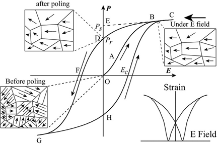
The disappearance of electric domains in a direction different from that of the electric field and the nucleation of electric domains in the same direction as the electric field causes hysteresis loop P(E) macroscopically (Figure 7). At point O, no electric field is applied to the ferroelectric body, the electric domains inside the ferroelectric body are disordered and randomly distributed and they do not show polarization externally. In the O-A segment, as the electric field increases, the polarization increases slowly because the domain wall movement between the electric domains only occurs due to the small electric field. In the A-B segment, as the electric field continues to increase, the polarization increases rapidly, at this time new domains begin to form and the domains in parallel or near-parallel electric field direction gradually increase and replace the other-oriented domains. In the B-C segment, the polarization reaches the maximum value. At this time, most of the electric domains of the ferroelectric are parallel or close to the parallel electric field direction and the inversion of the electric domains tends to saturate. Point C is called the maximum polarization (Pmax). In the C-D segment, as the electric field decreases, the polarization begins to decrease. When the electric field intensity is zero the intersection point D of the hysteresis loop and the vertical axis is called the residual polarization (Pr). When it reaches point F, the polarization at this time is zero, which is called the coercive field intensity (Ec). The ferroelectric will form a saturated hysteresis loop after cycling between the maximum value of the positive and negative electric fields and the energy required to reverse the domain twice is the same as the area surrounded by the hysteresis loop [23].
Figure 7. A typical hysteresis loop in ferroelectrics and strain-electric field curve. Reprinted with permission from [24]. Copyright 2013 The American Ceramic Society.

