In the current hydrocarbon economy, transportation is fueled primarily by petroleum. Burning of hydrocarbon fuels emits carbon dioxide and other pollutants. The supply of economically usable hydrocarbon resources in the world is limited, and the demand of hydrocarbon fuels is increasing, particularly in China, India and other countries.
Proponents of a world-scale hydrogen economy argue that hydrogen can be environmentally cleaner source of energy to end-users, particularly in transportation applications, without release of pollutants (such as particulate matter) or carbon dioxide at the point of end use. A recent analysis asserted that “most of the hydrogen supply chain pathways would release significantly less carbon dioxide into the atmosphere than would gasoline used in hybrid electric vehicles” and that significant reductions in carbon dioxide emissions would be possible if carbon capture or carbon sequestration methods were utilized at the site od energy or hydrogen production.
Hydrogen storage can be distributed continuously in pipelines or batch wise by ships, trucks, railway or airplanes. All batch transportation requires a storage system also pipelines can be used as pressure storage system. Hydrogen exhibits the highest heating value per weight of all chemical fuels. Furthermore, hydrogen is regenerative and environment friendly. But two difficulties with hydrogen are that hydrogen is just an energy carrier and has a low critical temperature of 35 K, i.e., hydrogen is a gas at room temperature. For mobile and in many cases also for stationary applications the volumetric and gravimetric density of hydrogen in a storage system is crucial. Hydrogen can be stored by six different methods and phenomena: high pressure gas cylinders (up to 800 bar), liquid hydrogen in cryogenic tanks (at 21 K), adsorbed hydrogen on materials with a large specific surface area (at T< 100K), absorbed on interstitial sites in a host metal (at ambient pressure and temperature), chemically bond in covalent and ionic compounds (at ambient pressure), oxidation of reactive metals e.g., Li, Na, Mg, Al, Zn with water. These metals easily react with water to the corresponding hydroxide and liberate the hydrogen from the water. Finally, the metal hydroxides can be thermally reduced to the metals in a solar furnace.
In conclusion, routes for the transmission and storage of hydrogen for chemical processes, and hydrogen-based energy systems are increasing their establishment. Here, these routes are described, considering their attractions and difficulties.
- Hydrogen Storage and Transportation
1. Introduction
In a previous paper[1], it has been shown that hydrogen is the ideal fuel from ecological viewpoint. In fact, it may, in principle, be derived from water using a non-fossil energy source (e.g., solar, geothermal, nuclear) and combusted back to water in a closed chemical cycle involving no release of carbonaceous pollutants. Hydrogen also has potential to provide a storage component for renewable forms of energy and to transport this energy, via underground pipelines, from where it is produced to where it is needed. The topic on its production was explored in some detail in more recent paper[2].
Here, we are concerned with the distribution and storage of hydrogen[3][4][5]. The attractions of hydrogen as a storage medium are:
- it is universally available in the form of water, from which it may be extracted conveniently by electrolysis;
it is universally available in the form of water, from which it may be extracted conveniently by electrolysis;
- it may be transmitted over long distances in buried pipelines, which are cheaper to construct and operate than electricity grids, and have no visual impact;
it may be transmitted over long distances in buried pipelines, which are cheaper to construct and operate than electricity grids, and have no visual impact;
- the gas in the pipeline provides a storage component within the electricity supply system;
the gas in the pipeline provides a storage component within the electricity supply system;
- hydrogen is the ideal fuel for use in fuel cells to generate electricity;
hydrogen is the ideal fuel for use in fuel cells to generate electricity;
- hydrogen is oxidized cleanly to water, therefore the cycle is closed and no significant pollutants are
hydrogen is oxidized cleanly to water, therefore the cycle is closed and no significant pollutants are
Hydrogen can be transported in pipelines similar to natural gas. There are networks for hydrogen already operating today, a 2000 km network in Europe and a 1,000 km network in the USA.
The volumetric energy density of hydrogen gas is 36% of the volumetric energy density of natural gas at the same pressure. In order to transport the same amount of energy the hydrogen flux has to be 2.8 times larger as compared to natural gas. However, the viscosity of hydrogen (8.92 x 10⁻⁶ Pa s) is significantly smaller than that of natural Gas (11.2 x 10⁻⁶ Pa s). The minimum power P required to pump a gas trough a pipe is given by

where 


2. Gaseous Hydrogen
In principle, hydrogen is an ideal vector for the transmission and storage of energy[6][7][8]. One might imagine, in the post-fossil-fuel age, huge solar collectors and electrolysis plants located over large areas of desert. It would then be necessary to convey the hydrogen to market. The most obvious means would appear to be via pipeline. Indeed, as long as 1938, conventional mild-steel pipelines were installed in the Ruhr district of Germany to convey hydrogen between refineries and chemical works. The initial system was about 24 km long and fed two plants. Since then, the grid has been expanded to a 210 km network that links four producers of gas and thirteen users. It even crosses the Rhine in two places. The pipes are wrapped in bitumen and plastic, have diameters of 15-30 cm, and operate at pressures up to 1.6 MPa (16 atm.). Remarkably, no major accidents have arisen from escaping hydrogen or potentially explosive hydrogen-air mixtures. There is also a 100 km system in Northern France and a total of some 2000 km in Europe as a whole. North America has at least 1000 km, and other smaller networks are in use in South Korea and Thailand. Clearly, the technology of transmitting pressurized hydrogen safely over considerable distances has been demonstrated and used commercially to supply gas for chemical processes.
Hydrogen, as an energy vector, is a rather different proposition since the distances involved are likely to be much greater and the allowable cost much less. Moreover, it is by no means certain that in place networks for natural gas can be adequately and safely used for the distribution of hydrogen, given the tremendous diversity of materials that are employed, e.g., iron, steel and plastic for pipes, brass for valves, natural and synthetic rubber for mechanical joint seals ant meter diaphragms, lead and jute for sealing compounds, and cast aluminium for meter housings and regulator parts. In particular, problems may arise from hydrogen leakage through gaskets and valves, and from hydrogen attack of certain metals (blistering, embrittlement, decarburization). Hydrogen is compatible with aluminium, brass, low-carbon steels and polymers, but not with high- carbon steels, high strength alloys and titanium. Plastic pipes (made from polyvinyl chloride or the newer high-density polyethylene) that are employed in some natural-gas lines are too porous and not suitable for transporting hydrogen. Over a long distance, there will also be a need to re-pressurize regularly, perhaps every 100 km or so, and this will represent a further loss of energy. The distant transmission of energy, whether as electricity, natural gas or hydrogen, will involve some losses and it has to be assessed whether the losses are too large and if they are economically acceptable[9][10][11][12][13][14][15].
The low volumetric energy density of hydrogen means that, to deliver a given amount of energy, the flow rate through the pipeline must be much faster than that for natural gas, i.e., by a factor of 2.8. As a consequence, and despite the lower viscosity of hydrogen, flow resistance is greatly increased so that, for a given delivery rate, more energy is required to move hydrogen in relation to natural gas.
Nevertheless, at standard and safe pipeline pressures and provide that the above mentioned problems can be overcome, it is considered that existing networks could deliver as much as 85% of the energy transported nowadays by natural gas to the end user. It should be further noted that hydrogen gives rise to greater problems than natural gas when new lines have to be installed or when old lines have to be repaired. Also because hydrogen burns in such a wide range of air mixture ratios, new installations have to be purged with an inert gas. Although the basic feasibility of distributing hydrogen via extensive pipelines is not in dispute, forecasts of the implementation costs vary widely according to the method use, i.e., between 1.5 and 3 times that for natural gas. This uncertainty is not surprising given the profuse number of variables that come into play. These include: choice of materials; pipeline diameters and pressures; types of valves, compressors, sensors and safety devices; spacing and fuel costs of compression stations; embrittlement; the geographical locations of sources of hydrogen.
The next problem is how to store gaseous hydrogen in bulk. To some degree, the pipelines themselves would provide a storage component-just as they do for natural-gas grids in many countries. For many years, natural gas has been seasonally held underground in depleted oil and gas fields on a huge scale (especially in the USA) and this is a low-cost storage option. The ability to store gas underground depends critically on the nature of the rock strata. Porous permeable rock is required, while sealing of the system is accomplished by the capillary action of water in the cap-rock above the reservoir. In addition to using depleted gas fields, it is also possible to contain the aquifers simply by displacing water and creating an artificial storage volume, always providing that there is impermeable cap-rock present to prevent gas escape. In France, for example, a country that gas in porous lacks oil or gas fields, a number of aquifer stores have been used for natural gas, which includes one of 200 000 m' capacity outside of Paris[16][17][18].
The question then is: could such storage means be used equally well for hydrogen? The main difference between hydrogen and natural gas lies in the smaller size of the hydrogen molecule and its higher diffusion coefficient, both factors that would tend to facilitate escape from the store. Fortunately, the size of the pores in cap-rock is sufficiently small that the water is displaced only with difficulty and, provided that gas pressures are not excessive, the cap-rock will serve to retain the hydrogen. Indeed, the higher diffusion coefficient of hydrogen should make the reservoir easier to fill and empty than with natural gas. Other options for underground storage are abandoned mines, natural limestone caves, or man-made cavities in underground salt deposits. The salt cavities are made by drilling down into the deposit and injecting water to dissolve out the salt. Since salt is itself impermeable, it forms an excellent container for the gas. Nevertheless, the excavation costs make this option less attractive than the use of existing man-made or natural cavities. In the final analysis, the form of underground storage, if any, that will be employed is determined by the geology. One operational problem with underground storage is that a fairly large amount of "cushion" gas has to be written-off initially in order to build up and maintain the underground pressure so that the recoverable part can be extracted later. Rock caves allow a 25% turnover in capacity per storage cycle, and wet salt cavities may approach 100% turnover. Despite these considerations, there have been some commercial examples of underground hydrogen storage. For example, ICI has stored 95%-pure hydrogen at 50 MPa in salt caverns at Teeside, UK, for use by industrial customers, and Gaz de France has stored town gas containing 50% hydrogen in an aquifer.
On a much similar scale, compressed hydrogen may be stored in pressure vessels. This requires the use of specialized compressors. Industrial customers of hydrogen sometimes use above-ground storage in vertical rows or horizontal stacks of cylinders at pressures in the range of 20 MPa up to a maximum of 80 MPa. Such high pressures require thick-walled and heavy steel containers. In the past, failures have been experienced through stress induced by hydrogen embrittlement and, consequently, cylinder manufacture is now subject to strict standards and codes of practice. Tank storage is modular with little economy of scale. For portable and mobile applications (e.g., fuel for road vehicles), both weight and volume are vital considerations, and it is desirable to have storage densities as high as possible. Conventional steel cylinders are limited in terms of storage energy density. Improvements may be affected by using modern materials instead of steel. This implies high pressures and lightweight vessels. At present, the best lightweight vessels are composed of wound carbon-fibre shells with aluminium liners. The most common design - due to its ease of fabrication and therefore, lower cost - is the hoop-wound design, in which the composite wrapping is only applied to the liner along the parallel section (vertical walls) of the cylinder. In the fully wound design, the composite covers the entire external surface of the cylinder. The liner acts as a gas-impervious barrier which, for hoop wound cylinders also provides considerable strengthening. A number of polymeric materials, e.g., ultrahigh-molecular-weight polyethylene, have also been examined as possible liners, but permeation/ leakage of hydrogen raises safety issues. Both designs of vessel will withstand an internal pressure of 55 MPa and provide a theoretical energy density of 6.9 MJ dm-3, which reduces to a practical value of 3-4 MJ dm-3 when account is taken of the volume of the cylinders and their packing. Improvements in technology are required to meet the target of 9.7 MJ kg- 1 by 2015 that has been set by the US FreedomCAR Partnership for hydrogen stores on electric vehicles (EVS) powered by fuel cells. The corresponding US gravimetric target of 10.8 MG kg-1 is still more difficult to reach.
Storage vessels made of high-tensile steel are not suitable for most portable or transportation applications but can store hydrogen at up to 80 MPa. Even at this maximum pressure, which requires special cylinder manufacture, the theoretical value for the volumetric energy storage (10 MJ dm-3) does not start to compare with that of methane at the same pressure (32 MJ dm-3), or with liquid octane (34 MJ dm-3) or liquid propane (25 MJ dm-3). Clearly, compressed hydrogen gas poses a major storage problem for road vehicle applications in terms of both weight and volume. If the above mentioned lightweight canisters made of carbon-fibre composite are employed, then the cylinder volume required for a given vehicle range would be about five times larger than that of a petrol tank holding a corresponding amount of energy.
A further problem is the amount of electrical energy needed to operate the compressors. (Note - the compression process could be reduced, or eliminated altogether, if the hydrogen was supplied from pressurized electrolyzers and this is a prospect for the future). It has been estimated that the electricity required to compress hydrogen to 20 MPa is equivalent to over 7% of the energy content of the hydrogen. The figure rises to 10% for compression to 80 MPa. Added to this is the fact that cylinders do not pack as well as single container and it is clear that the proposition of using compressed hydrogen gas as a fuel for most small vehicles will result in restricted driving ranges. For example, the Honda “FCX” and Toyota “FCHV” fuel-cell powered cars are equipped with high- pressure tanks and have ranges of only 270 and 288 km, respectively. A more promising application of this storage technology is in fuel-cell buses, such as the Toyota “FCHV- Bus 2”, as these vehicles operate on fixed routes. It should be noted, however, that the refilling time for compressed hydrogen is similar to that of petrol. A pioneer station for the rapid refuelling of hydrogen-powered vehicles has been installed at the Powertech Labs. in British Columbia, Canada. The gas is stored underground at 87.5 MPa and dispensed at 70 MPa.
3. Liquid Hydrogen
Liquid hydrogen (LH2) is a cryogenic liquid that boils at 20K. Superficially, this is an attractive way to store hydrogen on account of its compactness compared with gaseous hydrogen; the relative density factor is about 850[19][20]. There are, however, some serious drawbacks. First the liquefaction process itself requires the expenditure of a considerable amount of energy. The theoretical amount of energy required is about 4 MJ of electricity per kg of hydrogen although, in practice, many times this amount is used and depends on the scale of operation. For large liquefaction plants (1 000 - 10 000 kg h-1), the energy input is equivalent to about 30% of the energy value of hydrogen itself and rises to equal or exceed this figure in small-scale operations. Next, the cryogenic equipment to liquefy and contain the hydrogen is sophisticated and costly. Finally, even with good insulation, such as multi-layer vacuum super-insulation, the boil-off rate is such that LH2, in kilogram quantities can only be stored for a few days at most. Clearly, liquid hydrogen is not a practical proposition as a fuel for most road vehicles even before the efficiencies and costs of renewable electricity and electrolyzers are taken into account. Despite this, some automotive manufacturers have persisted with trials of LH2-fueled vehicles[1][21][22][23][24].
Liquid hydrogen has, however, been produced in substantial quantities for use in nuclear bubble chambers (for observing the paths of charged particles), space rockets, etc.[25][26][27][28][29][30][31][32][33][34][35][36]. In the 1970s, NASA required a continuous supply of LH2, as rocket fuel for the Apollo program. Spherical, vacuum jacketed containers were built to hold over three million litters of cryogenic liquid. It was also shipped across the USA in cryogenic rail cars. Nowadays, LH2 is also transported by road in tank trucks and by sea in tank ships. The latter are similar to LNG tankers apart from the fact that better insulation is required to keep the hydrogen cool over long distances. Hydrogen that is unavoidably evaporated may be used as fuel on board. Although the technology for handling LH2, in bulk does exist, the limitations outlined above make it unlikely that LH2 will be employed in situations where other storage forms for hydrogen will suffice. The possible use of liquid hydrogen as a fuel for aircraft has been discussed in our previous paper[1].
4. Metal Hydrides
An alternative storage procedure, which is much better matched to the likely scale of solar energy installations or hydrogen-fuelled road vehicles, is to store hydrogen in the solid state as a metal hydride[36][37][38][39][40]. A number of metals and alloys absorb hydrogen reversibly to form metal hydrides. The hydrides are classified into five families denoted as A, A2B, AB, AB2, and AB5, where metal A is an early transition metal (e.g., titanium, vanadium), a rare-earth metal or magnesium, and B is aluminium, chromium, cobalt, iron, nickel or manganese. The key to the practical use of metal hydrides is the ability to absorb and release the hydrogen many times without deterioration. The hydrogen is first dissociatively absorbed on the surface and then hydrogen atoms diffuse into the metal/alloy. These dissolved atoms can take the form of a random solid solution or an ordered hydride structure, both with a high volumetric packing density. The quantity of hydrogen absorbed is expressed in terms of hydride composition, either on a molar or a weight-percent basis. Volumetrically, the hydrogen content may be as high as that in liquid hydrogen. Some of the metal hydrides are of quite variable composition (i.e., variable metal-to-hydrogen ratio), whereas others have only a narrow range of composition.
The absorption process is generally exothermic. Thus, in order to absorb hydrogen continuously to the maximum capacity, heat must be removed. The direction of the hydrogen absorption-desorption process is determined by the pressure of the hydrogen gas. If the pressure is above the equilibrium value, then the hydride will be formed. Conversely, below the equilibrium pressure, hydrogen is released and the metal/alloy returns to its original state. The equilibrium pressure itself depends on temperature. This relationship is expressed by the van't Hoff equation, i.e.
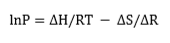
where P is the dissociation pressure; ΔH is the change in enthalpy, R is the gas constant, T is the absolute temperature; and ΔS is the change in entropy[2]. The value of ΔH can vary widely from metal/ alloy to metal/alloy. By contrast, ΔS does not vary as much. For a given metal hydride, the van't Hoff plot of lnP versus 1/T is a straight line and provides a useful illustration of the hydrogen absorption-desorption characteristics. The dissociation pressure curves for a number of metal hydrides are presented in Figure 1. These plots show that hydrides can be broadly classified into three categories, namely: HT, medium-temperature (MT) and low-temperature (LT) hydrides. The LT category is the most useful in that such hydrides offer hydrogen storage closest to ambient temperature and are therefore convenient for supplying fuel cells. In this case, the required enthalpy of hydrogen desorption would be provided by the waste heat from the fuel cell.
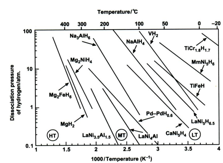
A great many alloys have been screened for hydrogen storage with respect to the allowing criteria: (i) reversible hydrogen capacity; (ii) ease of initial activation of the alloy; operating pressure-temperature range (van't Hoff plots); (iv) reaction kinetics; (v) stability on repeated cycling of hydrogen; and (vi) One of the first metal hydrides to be studied was LaNi5, which takes up hydrogen reversibly from LaNi5H6.5. Varyingamounts of zirconium or titanium may be substituted on the lanthanum lattice sites and aluminium, chromium, cobalt, manganese, vanadium on the nickel lattice sites. The hydriding reaction is reversible at ambient temperature and the enthalpy of reaction is ow (31 kJ per mole H2), which implies that not too much fast heat has to be supplied and removed. he alloy may be subjected to many hundreds of hydriding-dehydriding cycles without loss of capacity. Cycling is accompanied by a corresponding major expansion and contraction in volume that causes the alloy to disintegrate into a fine powder and, thereby, enhances the subsequent reaction kinetics. Unfortunately, lanthanum is an expensive metal and the hydride contains only 1.5 wt.% hydrogen.
Magnesium hydride, MgH2, (an A alloy), contains the highest percentage of hydrogen by weight (7.65 wt.%) and is inexpensive. Nevertheless, it has drawbacks. A temperature above 300 °C is required for the release of hydrogen (Figure 1) and the enthalpy of dissociation is high (75 kJ per mole H2), which requires the supply and removal of considerable quantities of heat as the hydride is decomposed and reformed, respectively. Moreover, the kinetics of the initial hydriding-dehydriding reaction are very slow unless an over-pressure many times the equilibrium dissociation pressure is employed. This limitation can be circumvented, at the expense of reduced gravimetric hydrogen content, by using the type A2B alloy Mg2Ni to form the hydride Mg2NiH4, which contains 3.6 wt.% hydrogen. In addition, Mg2Ni is readily activated, has good reaction kinetics, and cycles reversibly at a rather lower temperature than MgH2.
Vanadium hydride, VH2, has a favourable dissociation pressure at near-ambient temperature, but only one hydrogen atom may be removed reversibly, and this results in a hydrogen storage capacity of just 1.9 wt.%. The enthalpy of decomposition is moderate (40 kJ per mole H2). The titanium-iron alloy, TiFe (type AB), forms a hydride TiFeH1.5 that is also usable at ambient temperature and has a low enthalpy of decomposition (28 kJ per mole H2), but its reversible hydrogen content is only 1.5 wt.%.
From the above studies, the following characteristics have been identified as being desirable for alloys to serve as practical hydrogen-storage media[41][42][43][44][45].
- the dissociation pressure of the alloy should have a value of 0.1-1 MPa at near- ambient temperature;
the dissociation pressure of the alloy should have a value of 0.1-1 MPa at near- ambient temperature;
- the hydride should have a high hydrogen content per unit mass;
the hydride should have a high hydrogen content per unit mass;
- the alloy should be of low cost and should be readily prepared;
the alloy should be of low cost and should be readily prepared;
- the system should exhibit favourable and reproducible reaction kinetics;
the system should exhibit favourable and reproducible reaction kinetics;
- the enthalpy of hydride formation should be as low as possible;
the enthalpy of hydride formation should be as low as possible;
- the bed of reactant should have a high thermal conductivity;
the bed of reactant should have a high thermal conductivity;
- the alloy should not be poisoned by gaseous impurities;
the alloy should not be poisoned by gaseous impurities;
- the system should be safe on exposure to air and should not
the system should be safe on exposure to air and should not
No alloy meets all these specifications and the choice of alloy will be a compromise based upon the intended application. LaNi5 is a good choice for many applications, but it is expensive. Research on alloys for use in nickel-metal-hydride batteries has led to new hydrides based on mixed rare-earth metals ("misch metal”, Mm) that are both superior in properties and cheaper than pure LaNi5, e.g., MmNi5H6 (Figure 1).
In order to develop a successful hydride bed on a large scale, it is necessary to investigate not only the basic chemistry of the hydrides themselves, but also the chemical engineering of such beds. During the 1970s, a major work program was carried out by Brookhaven National Laboratory in the USA to construct and test a large hydride bed that would be suitable to store the hydrogen required to power a hydrogen-fuelled road vehicle. The pilot bed contained 400 kg of FeTi alloy and was capable of storing 5.5 kg of hydrogen. A study was made of heat and mass transfer effects in a bed of this size. It was demonstrated that the bed could be charged with hydrogen in 5 h, with an associated temperature rise of 37°C. A charging pressure of about 3.5 MPa had to be applied.
The studies demonstrated the feasibility of scaling-up hydride beds to realistic sizes for use with industrial-scale electrolyzers, although by no means all the engineering problems were solved. In the late 1970s, the Daimler Benz motor company converted a number of Mercedes-Benz vehicles (cars, vans and a minibus) to hydrogen operation and equipped them with hydride beds. In the case of the minibus, a TiFe bed (ambient temperature) was used for start-up and an MgNiH4, hydride bed (300 °C) for supplying hydrogen when hot. Eventually, this program was abandoned as not being economic in the prevailing circumstances. Further scale-up work must await both outcomes from basic scientific studies on newly discovered hydrides and changing economics of fuel supply.
5. Chemical and Related Storage
Organic liquids such as cyclohexane, can serve as chemical carriers of hydrogen. The gas is subsequently recovered by catalytic decomposition. Methanol (CH3OH) is usually manufactured from synthesis gas by the catalytic reaction of two molecules of hydrogen with one of carbon monoxide. It is an extremely versatile chemical in its own right and is used to a limited extent as a motor fuel, e.g., in certain classes of racing cars. Since established economic processes for the production of methanol exist, it is unlikely that it would be manufactured from electrolytic hydrogen and then decomposed back to hydrogen for use in a fuel cell. The overall energy efficiency of such a cycle would be very poor. Methanol derived from fossil fuel is, however, a prime candidate for fuel cells in road transportation and portable applications as it will be discussed in a following paper.
Hydrogen may also be stored chemically in the form of soluble ionic salts Na+[AHx]-, where A represents boron or aluminium; such compounds are generally known as “complex hydrides”. Sodium and lithium borohydrides are well known reducing agents that are used in organic chemistry. For hydrogen storage, the aluminium salts Na[AlH4]
and Na3[AlH6], (the so-called “alanates”) are the preferred reagents. Thermal decomposition of Na[AlH4] takes place in two steps, i.e.
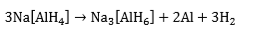

The reactions are reversible only at elevated temperatures and pressures (Figure 1). The first step at 50-100 °C, corresponds to the release of 3.7 wt.% hydrogen and the second step, at 130-180 °C, to a further 1.9 wt.% hydrogen. Research has shown that, in the presence of a titanium catalyst, the temperatures for discharge and recharge of hydrogen may be brought down to acceptable levels. Titanium-catalyzed Na[AlH4] has thermodynamic properties that are comparable with those of classic LT hydrides (e.g., LaNiH6 and TiFeH, Figure 1). Moreover, even if only the first reaction step can be used, the gravimetric hydrogen storage of Na[AlH4] is still more than that offered by AB, AB2, or AB5 hydrides. By contrast, Na[AlH6] requires higher temperatures for hydrogen liberation and might be useful for non-fuel applications such as heat pumping and heat storage. There are also complex hydrides based on transition metals, e.g., Mg2FeH6 (Figure 1). In most cases, they are reversible only with difficulty. The possibility of overcoming this limitation through catalysis awaits further research.
Sodium borohydride, NaBH4, is stable until about 400ºC and is therefore not suitable for providing hydrogen through a thermal activation process. It does release hydrogen, however, on reaction with water:
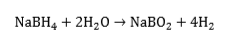
This is an irreversible reaction, but has the advantage that 50% of the hydrogen comes from the water - in effect, NaBH4, is a “water-splitting” agent. Based on the mass of NaBH4, the hydrogen released is 21 wt.% - a remarkably high figure. We have published several papers on the sodium borohydride and its possible applications[46][47][48][49][50][51][52][53][54][55][56][57][58][59][60]. Several of these so-called “chemical hydrides”, e.g., CaH2, LiAlH4, LiH, LiBH4, KH, MgH2, NaH, are being evaluated for their reactivity with water. One approach to preparing the storage medium is to mix the hydride with light mineral oil and a dispersant to form an organic slurry'. The oil coats the hydride particles and protects them from inadvertent contact with water, and also moderates the reaction rate of the hydride with water when desired.
The downside of using chemical hydrides is that the spent solution has to be returned to a processing plant for regeneration of the hydride. From the standpoint of mass, volume and cost, however, the system appears superficially to be attractive as a hydrogen- storage scheme for fuel-cell vehicles (FCVS). For example, DaimlerChrysler has demonstrated that a NaBH4, system, developed by Millenium Cell in the USA, can provide a minivan (the “Natrium”) with a range of 480 km. Much will depend on the difficulty and cost of the reprocessing operation. At the service station, instead of refuelling with hydrogen gas, the vehicle would have its tank emptied and refilled with a fresh hydride slurry. This is similar to the procedure proposed for the zinc-air traction battery.
Another possible approach to hydrogen storage stems from recent work on materials whose structural elements have dimensions in the nanoscale range. These so-called 'nanostructured materials have high specific surface areas (m2 g-1), which can be attained either by fabricating small particles or clusters where the surface-to-volume ratio of each particle is high, or by creating materials where the void surface area (pores) is high compared with the amount of bulk support material. Intense interest in such materials commenced in the early 1990s with the discovery of techniques to produce various types of carbon nanostructures. It was further shown that, at the nanoscale, materials can exhibit chemical and physical properties that are characteristic of neither the isolated atoms nor of the bulk material. Moreover, there is the opportunity to engineer the structural architecture to yield desired properties. With respect to hydrogen storage, the small size of nanostructured materials influences the thermodynamics and kinetics of hydrogen adsorption and dissociation by increasing the diffusion rate and decreasing the required diffusion length. The materials can divide into two categories[61][62][63][64][65][66][67][68][69][70][71][72][73][74][75][76][77][78][79][80][81][82][83][84]:
- "dissociative” materials, in which the hydrogen molecules are dissociated into atoms that bond with the lattice of the storage medium (chemisorption), e.g., metal hydrides, discussed
"dissociative” materials, in which the hydrogen molecules are dissociated into atoms that bond with the lattice of the storage medium (chemisorption), e.g., metal hydrides, discussed
- “non-dissociative” materials that by virtue of their high microporosity and high surface area store hydrogen in the molecular state via weak molecular-surface interactions (physisorption), e.g., carbon and boron nitride nanostructures, clathrates, metal-organic frameworks.
“non-dissociative” materials that by virtue of their high microporosity and high surface area store hydrogen in the molecular state via weak molecular-surface interactions (physisorption), e.g., carbon and boron nitride nanostructures, clathrates, metal-organic frameworks.
Clearly, physisorption is more desirable as it would moderate the pressure and temperature required for the respective uptake and release of hydrogen.
It has been shown that carbon, in the form of nanofibres or nanotubes (fullerenes), is capable of holding reasonable quantities of hydrogen. Various types of graphitic nanofibres have been investigated. These are grown by the decomposition of hydrocarbons or carbon monoxide over metal catalysts. The fibre consists of graphene sheets aligned in a set direction (dictated by the choice of catalyst). Three distinct structures may be produced: platelet, ribbon and herringbone, as shown in Figure 2 (a).
The structures are flexible and can expand to accommodate the hydrogen. Carbon nanotubes are cylindrical or toroidal varieties of fullerene (the generic term used to describe a pure carbon molecule that consists of an empty cage of 60 or more carbon atoms) and have lengths of between 10 and 100 µm. Each end is capped with half a spherical fullerene molecule. "Single-walled” nanotubes are formed by only one graphite layer and have typical inner diameters of 0.7-3 nm. “Multi-walled” nanotubes consist of multiple, concentric, graphite layers and show diameters of 30-50 nm. Examples of different types of carbon nanotube structure are shown in Figure 2 (b,c) Various pre- treatments have been suggested to enhance the storage capacity of such materials, which may amount to several wt.% hydrogen. There is still considerable controversy over the findings, however, because of the difficulty in preparing homogeneous, well-defined, pure and reproducible samples. Nevertheless, strenuous efforts are being made to develop methods for producing nanotubes economically on a large scale. For the present, hydrogen storage in carbon- and non-carbon-based nanostructured materials is no more than an outside possibility so far as FCVs are concerned, although it could be of interest in small-scale applications.
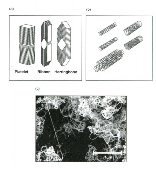
Figure 2. Schematic representation of (a) carbon nanofibres; (b) single- and multi-walled carbon nanotubes; and (c) electron micrograph of bundles of carbon nanotubes
6. Hydrogen Storage on Road Vehicles
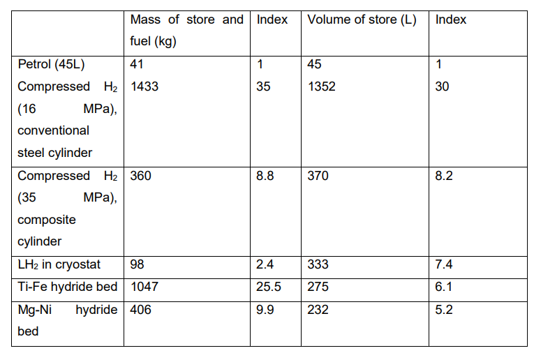
As seen above, the four main options for hydrogen storage in transportation applications are: compressed gas, liquid hydrogen, metal hydride, chemical carrier (at present, it is considered unlikely that nanostructured materials can accommodate the required amount of hydrogen). Table 1 gives a comparison of the probable masses and volumes that would be required to accommodate 11.75 kg of hydrogen, equivalent in energy content (1.4 GJ) to the energy contained in 45 L of petrol. The data may be only approximate, but they give some idea of the magnitude of the technical problems that have to be solved. In terms of mass, the only feasible option would appear to be liquid hydrogen, while in terms of volume none of the options appear to be practicable, unless a major reduction in vehicle range between refuelling stops is acceptable.
Table 1. Approximate comparison of masses and volumes of petrol and hydrogen for equivalent energy content (1.4 GJ)
It should also be recognized that an efficient method of storage is but one of a list of formidable issues that must be resolved if hydrogen is to be introduced successfully as a fuel for road vehicles[85].
These include:
- inertia to change an existing technology, industry, way of life;
- long time-scale for introducing a new energy industry and the large capital investment required;
- difficulties of manufacturing, distributing and storing hydrogen on the megatonne scale in a form /suitable for transportation applications;
- manufacture of hydrogen at a price that competes with natural or synthetic liquid fuels;
- technical issues of carrying hydrogen on the vehicle, e.g., volume of gas cylinders and their accommodation, mass of metal-hydride beds and their slow refuelling;
via intermediate electrolyzers, hydrogen distribution-storage and fuel cells is likely to involve low overall efficiency and high costs.
7. ConclusionIn this paper, the attractions of hydrogen as a transmission and storage medium were discussed.
It could be observed that while these attractions are still true in principle, many extraneous events have conspired to delay the widespread introduction of hydrogen- based energy systems, irrespective of whether the hydrogen is to be produced from fossil fuels or from renewables. Chief among these events have been the demise of nuclear energy programs, and the discovery of far more petroleum and natural gas than was foreseen in the 1970s[86][87][88][89][90]. Technological advances in conventional power production have also played a role, such as modern combined-cycle gas/steam turbines that are over 50% efficient in electricity production from natural gas. There are several reasons for this, namely:
- the discovery and exploitation of major new gas fields;
the discovery and exploitation of major new gas fields;
- the cleanliness of natural gas as a fuel;
the cleanliness of natural gas as a fuel;
- the development of high-efficiency combined-cycle gas turbines (CCGTs);
the development of high-efficiency combined-cycle gas turbines (CCGTs);
- the construction of pipelines and liquefied natural gas carriers to convey the gas to market[90]
the construction of pipelines and liquefied natural gas carriers to convey the gas to market
[9190].[91] - lingering doubts on the safety aspects of hydrogen, particularly in the context of retail sales to the public garages;
- practical aspects of joining high-pressure gas lines (or, in the case of LH2,cryogenic lines) to vehicles in a retail environment;
- competition from hybrid electric vehicles (HEVs), especially those with a diesel
Given this daunting list of obstacles, it seems unlikely that a supply and distribution network for hydrogen to fuel road vehicles will be widespread in the next 10 years. The situation is even more problematic when considering the production of hydrogen from clean renewable sources. The conversion of renewable electricity to traction effort
- .
A gas turbine of the type typically used in a CCGT station is shown in a dismantled state in Figure 3. The maintenance workers provide a clear indication of the size of the turbine. Other factors that bear indirectly on the situation are the widespread privatization of electricity utilities and the general imperative of short-term profitability that now pervades industry. In fact, from the viewpoint of the original concept of promoting efficiency and lowering the price of electricity, the de-regulation of electricity markets has certainly been a success. In the long term, however, problems loom large and arise from the fact that private companies tend to focus on short-term return and have little interest in making investments that will not show a profit for many years nor does the national interest enter much into this calculation. Quite simply, there is as yet no economic case for hydrogen energy and the time-scale on which it may become affordable is uncertain. Despite all these difficulties, however, interest in hydrogen energy and, of course, its production, distribution, storage, etc., is re-awakening, especially in the USA where there is acute appreciation of the forward supply position for oil and natural gas. Many industrial companies, as well as government and academia, are becoming involved in these matters.
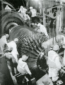
Figure 3. Dismantled gas turbine from CCGT power station
References
- Sequeira, C.A.C. Hydrogen, the ultimate clean fuel. Ciência e Tecnologia dos Materiais 2009, 21, 3/4, 44-47.
- Sequeira, C.A.C.; Santos, D.M.F.; Hydrogen production. Ciência e Tecnologia dos Materiais 2010, 22, 3/4, 76-86.
- Züttel, A.; Hydrogen storage and distribution systems. Mitigation and Adaptation Strategies for Global Change 2007, 12(3), 343- 365.
- Najibi, H.; Taghavi, N.; Effect of different parameters on optimum design for high pressure natural gas trunk-lines, Journal of Natural Gas Science and Engineering 2011, 3(4), 547.
- Damen, K.; van Troost, M.; Faaij, A.; Turkenburg, W.; A comparison of electricity and hydrogen production systems with CO2, capture and storage - Part B: Chain analysis of promising CCS options, Progress in Energy and Combustion Science 2007, 33(6), 576.
- de Wit, M.P.; Faaij, A.P.C.; Impact of hydrogen onboard storage technologies on the performance of hydrogen fuelled vehicles: A techno-economic well-to-wheel assessment, Int. J. Hydrogen Energy 2007, 32(18), 4859.
- Omura, T.; Kobayashi, K.; Miyahara, M.; Kudo, T.; Hydrogen embrittlement properties of stainless steels in high pressure gaseous hydrogen environment, Zairyo to Kankyo/Corrosion Engineering 2007, 55(4), 139.
- Omura, T.; Kobayashi, K.; Miyahara, M.; Kudo, T.; Effect of surface hydrogen contents on hydrogen embrittlement properties of stainless steels, Zairyo to Kankyo/ Corrosion Engineering 2006, 55(12), 537.
- Ipsakis, D.; Voutetakis, S.; Seferlis, P.; Stergiopoulos, F.; Elmasides, C.; Power management strategies for a stand-alone power system using renewable energy sources and hydrogen storage, Int. J. Hydrogen Energy 2009, 34(16), 7081.
- Damen, K.; van Troost, M.; Faaij, A.; Turkenburg, W.; A comparison of electricity and hydrogen production systems with CO2 capture and storage-Part B: Chain analysis of promising CCS options, (2007) Progress in Energy and Combustion Science 2007, 33(6), 576.
- Dryer, F.L.; Chaos, M.; Zhao, Z.; Stein, J.N.; Alpert, J.Y., Homer, C.J.; Spontaneous ignition of pressurized releases of hydrogen and natural gas into air, Combustion Science and Technology 2007, 179 (4), pp. 663.
- Shinnar, R.; The hydrogen economy, fuel cells, and electric cars, Technology in Society 2003, 25(4), 455.
- Verykios, X.E., Catalytic dry reforming of natural gas for the production of chemicals and hydrogen, Int. J. Hydrogen Energy 2003, 28(10), 1045.
- Bockris, J.O'M.; The origin of ideas on a Hydrogen Economy and its solution to the decay of the environment 2002, Int. J. Hydrogen Energy, 27(7-8), 731.
- Ogden, J.M.; Prospects for building a hydrogen energy infrastructure, Annual Review of Energy and the Environment 1999, 24, 227.
- Evans, D.J., Holloway, S.; A review of onshore UK salt deposits and their potential for underground gas storage, Geological Society Special Publication 2009, 313, 39.
- Evans, D.J.; A review of underground fuel storage events and putting risk into perspective with other areas of the energy supply chain, Geological Society Special Publication 2009, 313, 173.
- Evans, D.J.; Chadwick, R.A.; Underground gas storage: An introduction and UK perspective, Geological Society Special Publication 2009, 313, 1.
- Krasae-In, S.; Bredesen, A.M.; Stang, J.H.; Neksa, P.; Simulation and experiment of a hydrogen liquefaction test rig using a multi-component refrigerant refrigeration system, Int. J. Hydrogen Energy 2011, 36 (1), 907.
- Krasae-in, S.; Stang, J.H.; Neksa, P.; Development of large-scale hydrogen liquefaction processes from 1898 to 2009, Int. J. Hydrogen Energy 2010, 35(10), 4524.
- Wetzel, F.-J.; Improved handling of liquid hydrogen at filling stations: Review of six years' experience, Int. J. Hydrogen Energy 1998, 23(5), 339.
- Schmidtchen, U.; Gradt, Th.; Würsig, G.; Safe handling of large quantities of liquid hydrogen, Cryogenics 1993, 33(8), 813.
- Peschka, W.; Liquid hydrogen as a vehicular fuel - A challenge for cryogenic engineering, Int. J. Hydrogen Energy 1984, 9(6), 515.
- Peschka, W.; Operating characteristics of a LH2 - fuelled automotive vehicle and of a semi-automatic LH2-refuelling station, Int. J. Hydrogen Energy 1982, 7(8), 661.
- Nour, U.M.; Awad, S.; Yusup, S.; Sufian, S.; Technical evaluation of current hydrogen storage technologies for vehicles, J. App. Sci. 2010, 10(12), 1200.
- Aceves, S.M.; Espinosa-Loza, F.; Ledesma-Orozco, E.; Ross, T.O.; Weisberg, A.H.; Brunner, T.C.; Kircher, O.; High-density automotive hydrogen storage with cryogenic capable pressure vessels, Int. J. Hydrogen Energy 2010, 35(3), 1219.
- Paggiaro, R.; Bénard, P.; Polifke, W., Cryo-adsorptive hydrogen storage on activated carbon. I: Thermodynamic analysis of adsorption vessels and comparison with liquid and compressed gas hydrogen storage, Int. J. Hydrogen Energy 2010, 35(2), 638.
- Wang, H.; Gao, Q.; Hu, J.; Chen, Z.; High performance of nanoporous carbon in cryogenic hydrogen storage and electrochemical capacitance, Carbon 2009, 47(9), 2259.
- Meisner, G.P.; Hu, Q.; High surface area microporous carbon materials for cryogenic hydrogen storage synthesized using new template-based and activation-based approaches, Nanotechnology 2009, 20(20), art. no. 204023.
- Ahluwalia, R.K.; Peng, J.K.; Dynamics of cryogenic hydrogen storage in insulated pressure vessels for automotive applications, Int. J. Hydrogen Energy 2008, 33(17), 4622.
- Hu, Q.; Lu, Y.; Meisner, G.P.; Preparation of nanoporous carbon particles and their cryogenic hydrogen storage capacities, J. Phys. Chem. C 2008, 112(5), 1516.
- Aceves, S.M.; Berry, G.D.; Martinez-Frias, J.; Espinosa-Loza, F.; Vehicular storage in insulated pressure vessels, Int. J. Hydrogen Energy 2006, 31(15), 2274.
- Sarkar, A.; Banerjee, R.; Net energy analysis of hydrogen storage options, Int. J. Hydrogen Energy 2005, 30(8), 867.
- Aceves, S.M., Martinez-Frias, J., Garcia-Villazana, O., Analytical and experimental evaluation of insulated pressure vessels for cryogenic hydrogen storage, (2000) Int. J. Hydrogen Energy 2000, 25(11), 1075.
- Aceves, S.M.; Berry, G.D.; Rambach, G.D.; Insulated pressure vessels for hydrogen storage on vehicles, Int. J. Hydrogen Energy 1998, 23(7), 583.
- Peschka, W., Hydrogen: The future cryofuel in internal combustion engines, Int. J. Hydrogen Energy 1998, 23(1), 27.
- Chen, Y.; Sequeira, C.A.C.; Song, X.; Neto, R.P.C., Wang, Q; Polytipsu of La-Ni phases in multicomponents AB5 type hydride electrode alloys. Int. J. Hydrogen Energy 2002, 27, 63-68.
- Chen, Y.; Sequeira, C.A.C.; Neto, R.P.C., Wang, Q; Effect of pretreatment on the electrochemical properties of FeTi1.3 + 4.5% Mn alloys used as alkaline fuel cell anodes. Key Engineering Materials 2002, 230-232, 440-443.
- Song, X.; Chen, Y.; Sequeira, C.A.C.; Zhang, Z.; Lei, Y; Wang, Q.; Microstructural evolution of body-centred cubic structure related Ti-Zr-Ni phases in nonstoichiometric Zr-based Zr-Ti-Mn-V-Ni hydride electrode alloys. J. Materials Research 2003,18, 37- 44.
- Chen, Y; Sequeira, C.A.C.; Chen, C.; Wang, X; Wang, Q.; Metal hydride beds and hydrogen supply tanks as minitype PEMFC hydrogen sources. Int. J. Hydrogen Energy 2003, 28, 329- 333.
- Chen, Y; Sequeira, C.A.C.; Chen, C.; Wang, Q; Electrochemical properties of the ball-milled Ga1.8 Ca0.2 Mg14 Ni3 + x wt.% Ni composites (x=0.50, 100 and 200). J. Alloys Comp. 2003, 354, 120-123.
- Chen, Y; Chen, C.; Sequeira, C.A.C., Lixin, C; Qidong, W.; Hydrogen storage properties and phase components of Mg-doped Ti1-2Fe alloys synthesized by mechanical alloying. Trans. Nonferrous Met. Soc. China 2003, 13, 249-253.
- Santos, D.M.F.; Chen, Y; Sequeira, C.A.C.; Chronoamperometric determination of diffusion coefficients for borohydride anions in sodium hydroxide solutions. Defect Diffus. Forum 2008, 273-276, 583-589.
- Sequeira, C.A.C.; Chen, Y.; Santos, D.M.F.; Effect of sodium borohydride on the hydrogen diffusion in Mm Ni3.6Mn0.4Al0.3Co0.7 hydride electrode. Defect Diffus. Forum 2008, 273-276, 590-593.
- Sequeira, C.A.C.; Chen, Y.; Santos, D.M.F.; Effects of temperature on the performance of the MmNi3.6Co0.7Mm8.4Al0.3 metal hydride electrode in alkaline solution. J. Electrochem. Soc. 2006, 153, A1863-A1867.
- Santos, D.M.F.; Saturnino, P.G.; Macciò, D.; Saccone, A.; Sequeira, C.A.C.; Platinum-rare earth intermetallic alloys as anode electrocatalysts for borohydride oxidation. Catal. Today 2011, 170, 134-140.
- Santos, D.M.F.; Sequeira, C.A.C.; Chronopotentiometric investigation of borohydride oxidation at a gold electrode. J. Electrochem. Soc. 2010, 157, F16- F21.
- Santos, D.M.F.; Sequeira, C.A.C.; Cyclic voltammetry investigation of borohydride oxidation at a gold electrode. Electrochim. Acta 2010, 55, 6775- 6781.
- Santos, D.M.F.; Sequeira, C.A.C.; Determination of kinetic and diffusional parameters for sodium borohydride oxidation on gold electrode. J. Electrochem. Soc. 2009, 156, F67- F74.
- B. Šljukić, C.A.C. Sequeira, Ö. Metin, D.M.F. Santos. Mesoporous graphitic carbon nitride-supported binary MPt(M;Co;Ni;Cu) nanoalloys as electrocatalysts for borohydride oxidation and hydrogen evolution reaction. Catalysis Today, 2020, 357, 291-301.
- D.S.P. Cardoso, C.A.C. Sequeira, C.M. Bateman, J.E. Barker, E. Abbey, D.M.F. Santos, Electroreduction ability of organoborohydride compounds. J. Electrochemical Society, 2017, 164, M1-M7.
- M. Martins, B. Šljukić, C.A.C. Sequeira, Ö. Metin, M. Erdem, T. Sener, D.M.F. Santos. Biobased carbon-supported palladium electrocatalysts for borohydride fuel cells. Int. J. Hydrogen Energy, 2016, 41, 10914-10922.
- Santos, D.M.F.; Sequeira, C.A.C.; Zinc anode for direct borohydride fuel cells. J. Electrochem. Soc. 2010, 157, B13-B19.
- B. Šljukić, D.M.F. Santos, C.A.C. Sequeira, C.E. Banks. Analytical monitoring of sodium borohydride. Analytical Methods, 2013, 5 (4), 829-839.
- B. Šljukić, D.M.F. Santos, C.A.C. Sequeira. Manganese dioxide electrocatalysts for borohydride fuel cell cathodes. J. Electroanal. Chem., 2013, 694, 77-83.
- D.M.F. Santos, T.F.B. Gomes, B. Šljukić, N. Sousa, C.A.C. Sequeira, F.M.L. Figueiredo. Perovskite cathodes for NaBH4/H2O2 direct fuel cells. Electrochim. Acta, 2015, 178, 163-170.
- Y. Chen, D.M.F. Santos, C.A.C. Sequeira, Metal hydrides for hydrogen storage and distribution. Ciência & Tecnologia dos Materiais 2011, 23, 1/2, 48-52.
- D.S.P. Cardoso, B. Šljukić, N. Sousa, C.A.C. Sequeira, F.M.L. Figueiredo, D.M.F. Santos. On the stability in alkaline conditions and electrochemical performance of A2BO4 – type cathodes for liquid fuel cells. Phys. Chem. Chem. Phys. 2018, 2018 (20), 19045-19056.
- Santos, D.M.F.; Sequeira, C.A.C.; Sodium borohydride determination by measurement of open circuit potentials. J. Electroanal. Chem. 2009, 627, 1-8.
- Santos, D.M.F.; Sequeira, C.A.C.; Potentiometric monitoring of sodium borohydride in aqueous solutions. C.Tecn. Mater. 2008, 20/3-4, 31-34.
- Klontzas, E.; Tylianakis, E.; Froudakis,G.E.; On the enhancement of molecular hydrogen interactions in nanoporous solids for improved hydrogen storage, J. Phys. Chem. Let. 2011, 2(14), 1824.
- Catlow, C.R.A.; Guo, Z.X.; Miskufova, M; Shevlin, S.A., Smith, A.G.H.; Sokol, A.A.; Walsh, A.; Wilson, D.J., Woodley, S.M., Advances in computational studies of energy materials, Philosophical Transactions of the Royal Society A: Mathematical, Physical and Engineering Sciences 2010, 368(1923), 3379.
- Bryce C, T.; Stephen A. III S.; Luther, E.P., Nanoporous metal foams, Angewandte Chemie - International Edition 2010, 49(27), 4544.
- Li, Y.; Zhang, J.Z.; Hydrogen generation from photoelectrochemical water splitting based on nanomaterials, Laser and Photonics Reviews 2010, 4(4), 517.
- Pei, L.Z.; Wang, S.B.; Fan, C.G.; Recent progress and patents in silicon nanotubes, Recent Patents on Nanotechnology 2010, 4(1), pp. 10.
- Mandal, T.K.; Gregory, D.H; Hydrogen storage materials: Present scenarios and future directions, Annual Reports on the Progress of Chemistry - Section A 2009, 105, 21.
- Germain, J.; Fréchet, J.M.J.; Svec, F.; Nanoporous polymers for hydrogen storage, Small 2009, 5(10), 1098.
- Yürüm, Y.; Taralp, A.; Veziroglu, T.N.; Storage of hydrogen in nanostructured carbon materials, Int. J. Hydrogen Energy 2009, 34(9), 3784.
- Takagi, H.; Hatori, H.; Energy storage using carbon nanotubes, Journal of the Vacuum Society of Japan 2008, 51(4), 250.
- Sahaym, U.; Norton, M.G., Advances in the application of nanotechnology “hydrogen economy”, Journal of Materials Science 2008, 43(16), 5395.
- Bérubé, V., Radtke, G.; Dresselhaus, M.; Chen, G.; Size effects on the hydrogen storage properties of nanostructured metal hydrides: A review, Int. J. Energy Research 2007, 31(6-7), 637.
- Nechaev, Yu.S.; The nature, kinetics, and ultimate storage capacity of hydrogen sorption by carbon nanostructures, Physics-Uspekhi 2006, 49(6), 563.
- Pitkethly, M.; Curtis, S.; Nanomaterials and hydrogen storage, Fuel Cell Review 2005, 2(4), 25.
- Zhou, L.; Progress and problems in hydrogen storage methods, Renewable and Sustainable Energy Reviews 2005, 9 (4), 395.
- Melechko, A.V., Merkulov, V.I; McKnight, T.E., Guillorn, M.A., Klein, K.L.; Lowndes, D.H.; Simpson, M.L.; Vertically aligned carbon nanofibers and related structures: Controlled synthesis and directed assembly, J. Appl. Phys. 2005, 97(4), art. no. 041301, 041301-1.
- Di Monte, R.; Kašpar, J.; Nanostructured CeO2-ZrO2 mixed oxides, J. Mat. Chem. 2005, 15(6), 633.
- Wu, J.; Grimsdale, A.C.; Müllen, K.; Combining one-, two- and three-dimensional polyphenylene nanostructures, J. Mat. Chem. 2005, 15(1), 41.
- Ichikawa, T., Hanada, N., Isobe, S., Leng, H., Fujii, H., Composite materials based on light elements for hydrogen storage, Mat. Trans. 2005, 46(1), 1.
- Fakıoğlu, E.; Yürüm, Y.; Veziroğlu, T.N.; A review of hydrogen storage systems based on boron and its compounds, Int. J. Hydrogen Energy 2004, 29(13), 1371.
- Seayad, A.M.; Antonell, D.M.; Recent Advances in Hydrogen Storage in Metal- Containing Inorganic Nanostructures and Related Materials, Advanced Materials 2004, 16(9-10), 765.
- Becher, M.; Haluska, M.; Hirscher, M.; Quintel, A.; Skakalova, V.; Dettlaff- Weglikovska, U.; Chen, X.; Hulman, M.; Choi, Y.; Roth, S.; Meregalli, V.; Parrinello, M.; Ströbel, R.: Jörissen, L.; Kappes, M.M., Fink, J.; Züttel, A.; Stepanek, I.; Bernier, P.; Hydrogen storage in carbon nanotubes, Comptes Rendus Physique 2003, 4(9), 1055.
- Wronski, Z.S.; Materials for rechargeable batteries and clean hydrogen energy sources, Int. Mater. Rev. 2001, 46(1), 1.
- Schulz, R.; Huot, J.; Liang, G.; Boily, S.; Lalande, G.; Denis, M.C.; Dodelet, J.P.; Recent developments in the applications of nanocrystalline materials to hydrogen technologies, Mater. Sci. and Eng. A 1999, 267(2), 240.
- Koch, C.C.; Whittenberger, J.D.; Mechanical milling/alloying of intermetallics, Intermetallics 1996, 4(5), 339.
- Valentine, K., Acquaviva, J.; Foster, E.J.; Zhang, K.M; Transmission network- based energy and environmental assessment of plug-in hybrid electric vehicles, J. Power Sources 2011, 196(6), 3378.
- World Energy Outlook 2001 Insights, International Energy Agency: Paris, France, 2001.
- BP Statistical Review of World Energy 2003, June 2003; see www.bp.com.
- Hubert, M. King, Scientific American 1971, 225, 61.
- Shell Company website: www.shell.com (November 2001).
- New and Renewable Energy: Prospects in the UK for the 21st Century, UK Department of Trade and Industry: London, UK, March 1999.
- UK Energy in Brief, UK Department of Trade and Industry: London, UK, July 2003.