NiFe electrodes are developed for the oxygen evolution reaction (OER) in an alkaline electrolyser based on an anion exchange membrane (AEM) separator and fed with diluted KOH solution as supporting electrolyte. This study reports on the electrochemical behaviour of two different NiFe-oxide compositions (i.e., Ni1Fe1-oxide and Ni1Fe2-oxide) prepared by the oxalate method. These catalysts are assessed for single-cell operation in an MEA including a Sustainion™ anion-exchange membrane. The electrochemical polarization shows a current density of 650 mA cm−2 at 2 V and 50 °C for the Ni1Fe1 anode composition. A durability test of 500 h is carried out using potential cycling as an accelerated stress-test. This shows a decrease in current density of 150 mA cm−2 mainly during the first 400 h. The performance achieved for the anion-exchange membrane electrolyser single-cell based on the NiFeOx catalyst appears promising. However, further improvements are required to enhance the stability under these operating conditions.
1. Introduction
The role of H2 as an energy vector is becoming progressively a solid choice [1]. Although various processes to produce pure H2 are available (i.e., catalytic-, thermal- and electrochemical-based routes) [2][3][4][5][2,3,4,5], research is looking at how to improve the efficiency and reliability of these technologies. Electrolysis of liquid water is one of the most used technologies to produce pure and green H2, but several issues regarding to the use of a highly concentrate caustic solution (7 M KOH) as liquid electrolyte have hindered its wide use. For example, liquid alkaline electrolyte based electrolysers, using concentrated solution of KOH or NaOH [6][7][8][9][10][6,7,8,9,10], have shown significant corrosion effects on the hardware. These drawbacks have affected the wide use of this technology. On the other hand, several positive aspects mainly related to the low cost of materials used for the electrodes (i.e., noble metal-free materials) characterize these alkaline systems [11]. A solution to the issues caused by the use of concentrated liquid electrolytes is to develop alkaline electrolysers based on a solid polymer electrolyte separator with a zero gap configuration (membrane-electrode assembly) requiring less concentrated KOH solution [12].
Several important achievements concerning the electrolysis of liquid water are reported in the literature especially for the use of solid proton-conducting polymer membrane [13][14][15][16][17][13,14,15,16,17]. Although this technology sounds to be safer than the liquid alkaline-based electrolyser, issues remain because of materials cost. Nafion® membrane-based assemblies represent the proof-of-concept for this technology [7][18][7,18]. As this electrolyte operates under acidic conditions, this implies the use of noble materials for the electrodes. This is avoidable under an alkaline environment. Therefore, a technology that may combine the positive aspects of both acidic and alkaline electrolysers is nowadays under investigation. In the meantime, novel types of polymeric membranes characterized by hydroxide ion conductivity have emerged [19][20][21][22][23][24][19,20,21,22,23,24], although their stability is still an issue. Such electrolytes promise to solve the issues raising from the cost of materials for electrodes and from the use of concentrated liquid alkaline electrolytes [17]. As a result, developing advanced critical raw materials free (CRM-free)-based electrocatalysts has also become an important topic for research [17][25][26][17,25,26]. A key aspect in this context is to find a proper oxygen evolution reaction (OER) electrocatalyst for the anionic electrolysers since the kinetics of the anodic reaction are also slow in alkaline conditions [27]. Unsupported iridium-based catalysts represent the state-of-the-art OER catalysts for this technology [9][28][9,28]. However, iridium is expensive and one of the rarest element on earth [29]. Nickel/iron (NiFe)-based materials have shown good catalytic activity towards OER for many applications [30] and therefore, many synthetic methods are under development [31]. Pérez-Alonso et al. have prepared different Ni/Fe wt.% compositions for OER. The durability tests carried out at a fixed current density of 300 mA cm−2 during 70 h showed a potential of 2.1 V for the alkaline water electrolysis cell [32].
In the present work, we have prepared the NiFeOx electrocatalysts by using a simple and cost-effective procedure based on the oxalate method [40] [33] which is also amenable to scaling-up. The aim was to assess this preparation procedure as an appropriate method to produce CRM-free anode electrocatalysts suitable for application in AEM electrolysis. In this regard, a standard Pt cathode for hydrogen evolution was used. The results of the electrochemical experiments have been discussed in relation to the structural, morphological, and chemical surface properties of the developed materials. The presence of different phases on the catalysts surface may affect interaction with water and hydroxide species in solution producing different performance and stability characteristics under practical operating conditions in single cell.
2. Results and Discussion
2.1. Physico-Chemical Properties of (CRM)-Free Catalysts for Alkaline Electrolysis
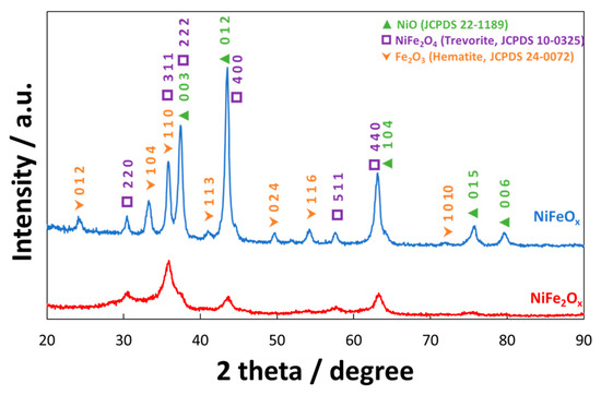
shows the X-ray diffraction spectrum (XRD) of NiFeOx
/KB and NiFe2
Ox
/KB electrocatalysts. A significant difference in the crystallographic structure has been observed, although both electrocatalysts were treated at the same temperature (i.e., 450 °C). The NiFeOx
catalyst (Ni:Fe = 1:1 at.) showed a crystalline structure ascribed to a spinel phase (i.e., JCPDS card n° 10-0325 of NiFe2
O4
) although also the presence of Fe2
O3
and NiO phases (JCPDS cards n° 24-0072 and 22-1189, respectively) was recognized. Therefore, the amount of these three main phases was evaluated through the least-square full-profile quantitative analysis procedure. Accordingly, the relative content of the three main phases was NiO (61.1 wt. %), NiFe2
O4
(26.3 wt. %), and Fe2
O3 (12.6 wt. %). All these phases have been shown to be active towards the oxygen evolution in alkaline solutions [34][35][36][37][38][39][40][41][42]. Their combination may produce a synergistic effect towards the oxygen evolution reaction. On the other hand, the NiFe
(12.6 wt. %). All these phases have been shown to be active towards the oxygen evolution in alkaline solutions [39,43,44,45,46,47,48,49,50]. Their combination may produce a synergistic effect towards the oxygen evolution reaction. On the other hand, the NiFe2
Ox
(Ni:Fe = 1:2 at.) has shown a less crystalline structure with a different phase composition. In this case, the quantitative analysis provided the following composition: NiO (26.1 wt. %), NiFe2
O4
(66.8 wt. %), and Fe2
O3
(9.7 wt. %). As consequence, the NiFe2
Ox
showed an enrichment in trevorite and a significant depletion in hematite and NiO phases.
Figure 1.
X-ray diffraction patterns of the NiFe
2
O
x
and NiFeO
x
catalysts calcined at 450°C. The catalyst formulations NiFe
2
O
x
and NiFeO
x
refer to a nominal atomic ratio Ni:Fe equal to 1:2 and 1:1, respectively.
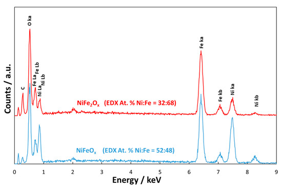
The EDX analyses () revealed that in the case of NiFeOx
the atomic ratio between the two metals was 1:1; whereas, in the case of NiFe2
Ox
, there was an enrichment of Fe with a Ni:Fe ratio close to 1:2.
Figure 2.
Energy Dispersive X-ray Analysis of the NiFe
2
O
x
and NiFeO
x
catalysts calcined at 450 °C. C is related to the carbon tape.
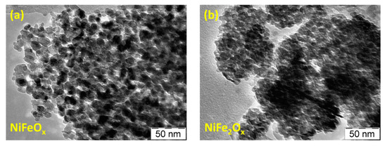
shows the TEM images of the bare catalysts. This analysis shows fine particles with an average crystallite size of about 5 nm for the NiFe2
Ox
and 10 nm for the NiFeOx
. A high grade of agglomeration for both specimens is observed, although the NiFeOx
seems to be slightly less agglomerated.
Figure 3.
TEM images of the NiFeO
x
(
a
) and NiFe
2
O
x
(
b
) catalysts.
reports the main physico-chemical properties determined from XRD, TEM, BET characterizations.
Table 1. Structural characteristics of the non-CRM Ni-Fe electrocatalysts.
| Concentration of Metal Oxide % |
|---|
| Crystallite Size (nm) XRD |
Particle Size (nm) TEM |
BET (m2 gr–1) |
|---|
| NiFeOx / KB |
70 |
12 |
10 |
50 |
| NiFe2Ox / KB |
70 |
5 |
5 |
141 |
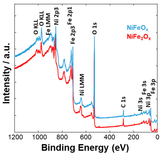
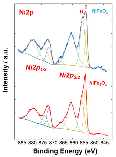
, and show a surface characterization of the bare NiFe samples carried out by X-ray photoelectron spectroscopy (XPS). The survey analysis () has shown similar electronic surface composition for both NiFeOx
and NiFe2
Ox
. Furthermore, the surface of calcined catalysts has not shown any relevant impurities. On the other hand, the signals ascribed to Ni2p have shown relevant differences between the two specimens (). The deconvolution of the asymmetric peak at around 855 eV associated to the Ni2p3/2
orbital has generated two peaks at 853.85 eV (band I) and at 855.42 eV (band II) and these have been ascribed to NiFe2
O4 and NiO, respectively [14]. Although both compounds contain mainly Ni
and NiO, respectively [14]. Although both compounds contain mainly Ni2+
, the peak of Ni2p3/2
for the NiFe2
O4
is shifted to lower binding energy as consequence of the presence of larger content Fe which is less electronegative compared to the Ni. This may have an impact on the intrinsic catalytic activity. Therefore, by comparing the Ni2p3/2
bands for the two specimens under investigation, there is a clear enrichment of NiO on the surface of the NiFeOx
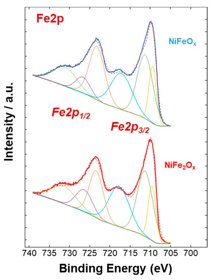
based specimen (), as recognized also by XRD analysis (). Concerning the bands ascribed to Fe2p (, there is no relevant difference in the surface composition for both specimens.
Figure 4.
XPS survey analysis of the NiFe-oxide catalysts.
Figure 5.
Ni2p XPS signals of the NiFe-oxide catalysts.
Figure 6.
Fe2p XPS signals of the NiFe-oxide catalysts.
2.2. Electrochemical Experiments
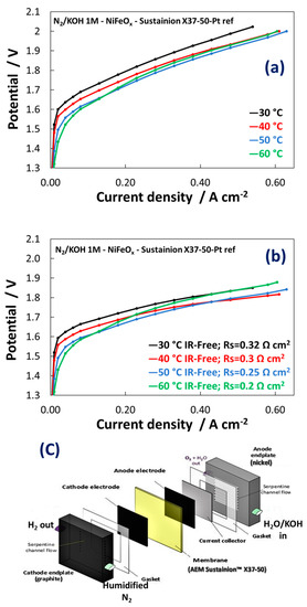
a shows the raw single cell polarization curves for the electrolysis process at a membrane-electrode assembly based on the Ni1
Fe1
-oxide catalyst as anode. b shows the same curves IR-corrected. Experiments were carried out in a single cell with recirculation of KOH 1 M at the anode (c) and in the temperature range 30–60 °C. As discussed, recirculation of diluted KOH in AEM electrolysers avoids dramatic loss of efficiency that would otherwise occur with pure water feed. On the other hand, concentrated KOH feed can exacerbate membrane degradation. 1 M KOH was considered as a trade-off between these two effects [43].
c) and in the temperature range 30–60 °C. As discussed, recirculation of diluted KOH in AEM electrolysers avoids dramatic loss of efficiency that would otherwise occur with pure water feed. On the other hand, concentrated KOH feed can exacerbate membrane degradation. 1 M KOH was considered as a trade-off between these two effects [51].
Figure 7.
(
a
) Polarization curves carried out at 1 M KOH for MEAs including the NiFeO
x
-based electrocatalysts at the anode; (
b
) IR-free polarisation curves; (
c
) Schematic illustration of the AEM electrolysis cell used in these experiments.
The polarization curves in a show an activation control (Butler-Volmer behaviour) up to 50 mA cm−2
. At higher current density, the polarization curves were controlled by the ohmic drop showing a linear dependence of the potential as function of current density in a wide range. The NiFeOx
KB (1:1) catalyst showed an increase in performance with an increase of temperature because of the kinetic constraints observed especially at low current densities. At 50 mA cm−2
the cell voltage decreased by more than 100 mV passing from 30 °C to 60 °C. In contrast, the increase of temperature affected only slightly the ohmic loss (b). This because the membrane ionic resistance was almost constant in the temperature range investigated. The slope of the curves was constant between 50 and 600 mA cm−2
. However, the membrane resistance played a relevant role in determining the voltage efficiency. The voltage gain was more than 100 mV at 0.6 A cm−2 in the IR-free curves. Although the increased temperature seems to affect positively the catalytic reactions on both electrodes, the anionic membrane generally suffers during operation temperatures close or higher than 60 °C because of degradation issues [44][45][46]. As a result, the best performance in this work has been achieved at 50 °C whereas at 60 °C a slight decrease in performance starting from 100 mA cm
in the IR-free curves. Although the increased temperature seems to affect positively the catalytic reactions on both electrodes, the anionic membrane generally suffers during operation temperatures close or higher than 60 °C because of degradation issues [52,53,54]. As a result, the best performance in this work has been achieved at 50 °C whereas at 60 °C a slight decrease in performance starting from 100 mA cm−2
has been observed. The MEA containing the NiFe2
Ox
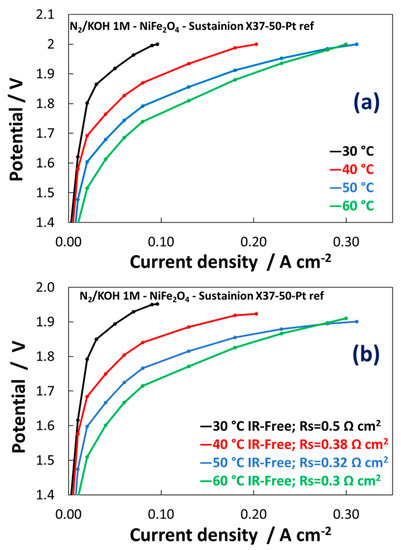
(Ni:Fe = 1:2) catalyst at the anode showed a different polarization behaviour with strong activation control in the overall range of current densities and larger series resistance compared to the MEA based on NiFeOx
(Ni:Fe = 1:1).
The activation control indicates poor reaction kinetics (a,b). Much lower performances have been achieved for NiFe2
Ox
vs NiFeOx
in the temperatures range here investigated. The main difference between the polarization curves of NiFeOx
and NiFe2
Ox
concerns with a strong activation control observed for the composition enriched in the spinel structure compared to that enriched in NiO. This may be related to the different absorption strength of oxygen species on the surface and the synergistic role of the different phases. As a result, the NiFe2
Ox
containing large excess of spinel phase is less active than the NiFeOx
towards the OER. The NiFe2
Ox
shows a slight shift of the Ni2p3/2
to lower binding energy possibly causing an increase of the strength of adsorption of oxygen species with a decrease of the rate of desorption of O2
molecules.
Figure 8.
Polarization curves carried out at 1 M KOH for MEAs including the NiFe
2
O
x
-based electrocatalysts at the anode. (
a
) Polarisation curves; (
b
) IR-free polarization curves.
The NiFeOx
is instead characterized by a proper content of NiO compared to NiFe2
Ox
and Fe2
O3 phases. NiO is a good catalyst for oxygen evolution in alkaline systems [47]. Its synergy with the spinel phase appears relevant to promote the OER process under practical conditions.
phases. NiO is a good catalyst for oxygen evolution in alkaline systems [55]. Its synergy with the spinel phase appears relevant to promote the OER process under practical conditions.
The performance of the present NiFeOx catalyst synthesized by the oxalate method appears superior than what has been previously reported in the literature for NiFe catalyst formulations in an alkaline water electrolysis cell [32]. A cell potential of 1.78 V is here recorded versus 2.1 V shown in the literature at 300 mA cm
catalyst synthesized by the oxalate method appears superior than what has been previously reported in the literature for NiFe catalyst formulations in an alkaline water electrolysis cell [32]. A cell potential of 1.78 V is here recorded versus 2.1 V shown in the literature at 300 mA cm–2 [32]. This corresponds to a gain of 13 % in terms of voltage efficiency.
[32]. This corresponds to a gain of 13 % in terms of voltage efficiency.
resumes the mass activities achieved at 1.5 V. At this potential the reactions are mainly affected by the kinetic control, as a result the best performances have been achieved at 60 °C (the highest temperature).
Table 2.
In-situ mass activity for the NiFeO
x
/KB and NiFe
2
O
x
/KB catalysts with the Sustainion™ membrane.
| Catalyst Formula |
Conditions |
30 °C
A g−1NiFe @ 1.5 V |
40 °C
A g−1NiFe @ 1.5 V |
50 °C
A g−1NiFe @ 1.5 V |
60 °C
A g−1NiFe @ 1.5 V |
| NiFeOx KB (70:30) |
1M KOH |
4 |
8 |
16 |
24 |
| NiFe2Ox KB (70:30) |
1M KOH |
4 |
4 |
4 |
8 |
Based on these preliminary experiments, the NiFeOx
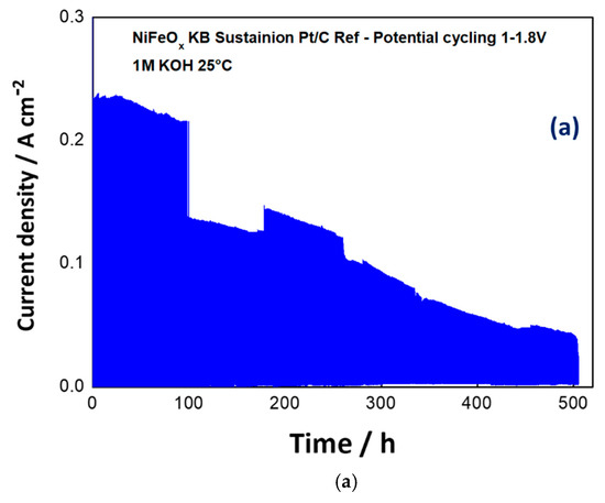
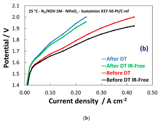
has been selected for a durability cycle (1–1.8 V) test of 500 h. The potential cycling experiment represents an accelerated stress test to evaluate the dynamic behaviour which is required to an electrolysis device in grid balancing service to convert the surplus of renewable energy in hydrogen. A life-time test has been carried out for 500 hours through the potential cycling between 1–1.8 V at room temperature and by feeding KOH 1 M at the anode. As shown in a, the maximum current density was more than halved during the stress test. Some discontinuities, essentially related to the replenishment of fresh KOH, have affected the experiment. However, the trend of performance loss was clear during the first 400 h. b shows the polarization curves before and after the life-time test. Based on the differences found in the polarization curves, the degradation is mainly ascribed to the catalyst (increase of the activation loss), whereas the ohmic drop was not significantly affected by the stress test.
Figure 9.
Potential cycling test (1–1.8V) for the NiFeO
x
KB (1:1) catalyst with the Sustainion™ membrane in 1M KOH (
a
) and polarization curves for the NiFeO
x
KB 70:30 catalyst based MEA before and after the accelerated stress test (
b
).
Therefore, based on these preliminary experiments, the NiFeOx
used for the OER needs to be improved especially in terms of stability under operation in alkaline conditions. This may be related to the excess of NiO compared to the spinel phase in the catalyst. A spinel structure is usually considered a robust option but the performance observed for the present NiFe2
Ox
needs to be ameliorated. An important aspect that requires further investigation is the effect of the crystallite size. The NiFeOx
shows larger crystallite size compared the NiFe2
Ox
(10 nm vs 5 nm). The OER is a structure sensitive reaction and its rate can be enhanced by modulating lattice characteristics. Tailoring composition and crystallographic properties may be also relevant to provide better stability under dynamic conditions.
3. Conclusions
Critical raw materials-free catalysts are a key topic to develop electrochemical technologies for hydrogen generation. In this regard, alkaline solid membrane-based electrolysers represent an interesting technology. Although Ni-Fe based materials are largely investigated as electrodes for OER reaction, further enhancements are still necessary in terms of composition, stability and facile synthesis methods for their preparation and utilisation in practical devices. In this paper, a simple method for the synthesis of two compositions of NiFe based materials (i.e., Ni:Fe = 1:1 and 1:2) was presented. These two materials were treated at the same temperature (i.e., 450 °C) showing different structures and surface compositions. The increased content of Fe affected the crystallinity and the occurrence of a spinel phase in the final electrocatalyst. A larger occurrence of the spinel phase on the surface of the catalyst containing a higher Fe content (i.e., NiFe2Ox) has been observed. As a result of the electrochemical tests, the increased content of NiO on the NiFeOx electrocatalyst surface positively affects the OER reaction rate. However, the electrochemical stress test consisting in a cycle (1–1.8 V) operation showed that the MEA based on NiFeOx was not sufficiently stable within the time investigated (500 h). Further efforts in preparing NiFe-based catalysts should be addressed to improve the composition of the catalyst’s surface and to modulate crystallographic properties and chemical characteristics.
