Protection Schemes for Electrical Distribution Networks with GDG: Comparison
Please note this is a comparison between Version 2 by Mona Zou and Version 1 by Ammar Abbas Majeed.

An amalgamation of Green Distributed Generation (GDG) with Distribution Networks (DNs) was developed because its performance became more efficient and sustainable. It increased the challenges in the design and operation of the protection scheme and changed the short circuit current (SCC), voltage profile, power losses, and power flow direction after the GDG penetration. These changes rely on the number, size, location, and environmental influence according to the GDG type. Therefore, many researchers have discussed protection system challenges and presented types of protection approaches to find a robust protection layout for DNs integrated with GDGs to prevent the electrical equipment from being destroyed during abnormal conditions.

  • protection scheme
  • Green Distributed Generation (GDG)
  • Protection Devices (PDs)
  • Distribution Networks (DNs)

1. Protection Scheme Challenges with GDG Existence

According to the new configuration of DNs, the protection system must be changed. The PDs connection must be designated in a suitable location and with optimal coordination to discriminate permanent faults from temporary faults. Predominantly, the protection design should primarily prioritize safety, reliability, and selectivity. This includes both primary and backup protection, aligned with the standard coordination time interval (CTI) and tailored to the power feeder sources, network connection type, and voltage level. In the presence of GDGs embedded in radial distribution networks (RDNs), conventional arrangements may not operate accurately due to some obstacles, such as in [6,10][1][2]:

1.1. Changes in Fault Currents and Short Circuit Level

There are two modes of operation in GDGs integrated with DNs, with the first designated by the islanded mode with a low fault current from the only source from the GDGs in the grid. The grid-connected mode has a high fault current because it consists of both injected currents from the GDGs and utility sources.
However, the GDG type, number, location, and capacity influence the contributed fault current directly [17][3]. For example, the fault current contributed by the inverter feed of a GDG from a small-scale PV system besides the DN has a fault current supplement up to 2 or 3 times its rated current, which should take its effect on the fault current into account [18][4]. During the electrical distribution planning process, the selection of PDs to protect different electrical equipment is established on this short circuit level [8][5], so a fault current increase leads to the short circuit level being excessive. Consequently, that will affect the setting and coordination of the PDs because the short circuit level represents the maximum fault current.

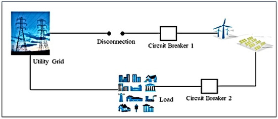
1.2. Bidirectional Power Flow

Embedded GDGs make a change in the DNs topologies, where a radial configuration with switches is modified for contiguous electrical feeder reliability from a bidirectional power flow. However, reconfiguration of the distribution network will modify the current flow direction and short circuit level, which directly influences the protection system. Therefore, adjustments in the PD settings are essential to absorb network disturbances. Failing to do so could lead to an increased PD operating time, potentially causing selectivity losses and miscoordination in the protection performance of embedded GDGs [19,20][6][7].

1.3. Unsynchronized Reclosing

The purpose of reclosing is to eliminate temporary faults in electrical networks that cause irrelevant perpetual blackouts. Nevertheless, GDG integration with a DN will increase the contribution of the fault current and affect the coordination performance between the primary and secondary PDs, so that the coordination will be missed [21][8]. A loss of PDs recloses the sync ability because the fault current level increases the effect of protection reliability.

1.4. Undesirable Network Islanding

A major problem associated with GDGs is the possibility of supplying part of the network that can be powered even if it is not connected, creating an unintended island. These can be detected using frequency-dependent characteristics [22][9]. This is built into the inverter interfaces of GDGs, available as a mandatory feature. UF/OF and UV/OV islanding detection have no impact on power quality, with cost-effectiveness [20][7].
In the case of an islanding operation system, resynchronization problems may occur, even in a short time. Then, the GDGs can be switched off to avoid device damage due to automatic reconnection without synchronization [23,24][10][11]. For personal safety assurance during grid maintenance, the anti-islanding protection method is used to justify the utility grid’s operational performance and to prevent reclosing in case of asynchrony.

1.5. Blinding and Maloperation of Undesired Tripping of PDs in the Protection System

When a large GDG is connected to a DN, the fault current seen by the feeder PD may change, followed by inaccurate or unavailable intelligent electronic device (IED) operation, which is called under-reach or blinding protection [25][12].
Meanwhile, the sensitivity of the PD decreases, and the wrong trip command occurs, leading to a blind in the protection system. So, the maloperation PD sends an undesired trip command as a faulty feeder, but the actual fault has a tack placed on another feeder at the same time [7][13]. Therefore, an overall protection agenda using an active adaptive protection system should be suggested to avoid PDs maloperations, such as protection coordination mismatch after a GDG is embedded within a DN.

1.6. Loss of Main (LOM)

Figure 31 represents a disconnection between the utility grid and the GDG. However, the connection between the GDG and the load remains. The CB maloperation problem is a normal result of non-robust PD operation and fault occurrence on the supply side.
Figure 31. Loss of main (LOM).
In this situation, part of the grid is still in operation, and the islanding mode is undetected by the PDs. Accordingly, a dangerous stage is reached before clearing the faults. Therefore, if the synchronism is not taken into account when connecting the GDG and the utility grid, it can lead to severe damage to the GDG and sensitive equipment in the DN [8][5]. Furthermore, this process can result in an uncontrolled voltage and frequency in the island network. It poses risks to the equipment and may cause unsynchronized reconnections, potentially leading to damage to customer equipment and measuring devices [2][14].

1.7. Topological Changes in the Power System

The location and bidirectional fault currents are changed by the size, type, number, and location of the GDGs. Nevertheless, topological changes in the operating mode (grid-connected to islanded and contrariwise) can significantly cripple the involved PDs setting [26][15]. Optimization algorithms are used to specify the optimal location, number, capacity, and GDG type with appropriate connections. The objective function concentrates on many criteria, such as power loss reduction, voltage level, and short circuit level.

1.8. Intermittent Nature According to the Environmental Effect on GDGs

The intermittent GDG’s power causes fluctuations in the injected power within the DN. This unpredictability arises from the randomly scattered cloud cover and changes in solar irradiation, leading to intermittent PV power generation, especially on cloudy days. The irregular changes in solar power during day hours cause power fluctuations and voltage variations. Therefore, making PD adjustments is a difficult task [27][16].
On the other hand, the definite generation technology in the WT model contains the entrail parts that regulate the short-circuit analysis with fault current contributions. Since the fixed speed type of a WT’s induction generator is connected directly to the DN, the machine has a suitable performance. These types of WTs, after connecting to the DN, are like providing large motor loads [28][17]. At a constant speed, WT power fluctuations and voltage flickers are the main problems for the grid.
In contrast, variable speed WTs produce a much more consistent output power with a stable bus voltage and power loss reduction. However, an extensive problem with WTs is that the stated net capacity is less than the rated capacity due to energy consumption and intermittent generation at the power plant [29][18]. Developing a key distribution system that balances stringent security and reliability with minimal hardware demands and manageable communication overhead is of paramount importance within the realm of wireless sensor networks (WSNs) [30][19].
Hence, there is a need to develop an economical, practical, and reliable protection layout for different types of GDGs (PV and WT) whose effectiveness does not depend on the type of GDG, type of fault, type of system (AC or DC), or the mode of operation, etc.

2. Protection Methodology with Detection Methods

The presence of GDGs with DNs leads to the breakdown of the ordinary protection design [31][20]. When the number of GDGs in the distribution power systems increases, the utility contribution fault current from the network substation will decrease [32][21]. Embedding a GDG leads to significant protection problems for electrical networks, such as increased PD sensitivity and inappropriate protection coordination [33][22]. Therefore, during the last two decades, the authors discussed some protection models to find proper methods with different technologies. Some protection frameworks are illustrated below.

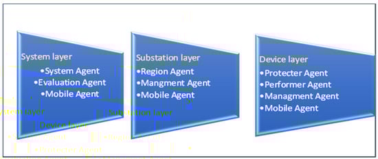
2.1. Multi-Agent System (MAS)

The suggested protection measures established the concept of more than one stage to exchange the information of protection networks using a communication platform. Collecting information from the elements of the power grid and performing computational operations are processes performed by an electronic device called an agent. This device can communicate with other agents using a communication network [34][23].
The structure of a MAS attempts to determine the exact operation of relay agents based on the network data of the protection system. A bi-level protection system in the relay uses the generation agents to mitigate their dependence through the information collected from the network by the central controller. The proposed system increased the reliability of the protection system and reduced the time required to collect the network data necessary to update the protection setting [25][12]. The effect of the capacity and type of GDG on the proposed clarification was neglected in this study. An adaptive protection protocol and multi-agent-based integration with the SHS were discussed to minimize the adverse impacts of a GDG on a DN. A negotiation strategy was employed to increase the load area to be recovered. Also, the SAPMS approach provided a new setting to the relays with a six-time shorter interval period than a short-term interruption defined according to the IEC 50160 standard [15][24]. This approach does not investigate GDG penetration with an environmental performance influence.
Furthermore, a hierarchical protection system (HPS), as a complementary protection strategy for a multi-agent system (MAS), can manage the generated power of the GDGs to limit the protection system coordination impact on the DNs. Consequently, using MAS technology with a distributed structure of (point-to-point) communication and quick decisions independently in a flat state can be useful.
A reduction in the number of agents is the main advantage of the proposed scheme since only relay agents are used, and no communication with the above layers of the MAS is required [35][25]. To avoid a communication failure, the agents will respond to the failure condition by using the available data for similar conditions. Therefore, protection coordination between the primary and secondary PDs happens by alternating the data between the relay agents to modify the relay’s time of operation [36][26]. The main drawback of this study was choosing the WTG location, size, and number without using optimization strategies to specify their effect precisely. The architecture for the multi-agent system developed for adaptive PDs comprises three levels, namely, the device level, the substation level, and the system level, as shown in Figure 42 [2,8][5][14].
Figure 42. Architecture for the multi-agent system.

2.2. Fault Current Limiter (FCL)

Conventional, radial, and mesh networks are protected by coordinated overcurrent relays, reclosers, or fuses, depending on the voltage level and the load type. GDG penetration will change the protection plan and the need to improve the PD model with different protection systems. The use of fault current limiters (FCLs) with electrical power systems represents an applicable procedure for reducing the level of SCC. During faults, a FCL is used to boost the impedance against the fault current path. Utilizing a FCL integrated with power systems offers numerous advantages, including a reduction in the voltage drop and SCC during faults. It also enhances the overall reliability and stability of the power system, while their high cost is the main disadvantage of using FCLs. Therefore, to get a very high performance from FCLs, the optimal numbers and locations of these devices should be studied carefully [37][27].

2.3. Overcurrent Relay and Earth Fault

The most familiar PDs used with DSs are overcurrent relays since traditional distribution systems are designed for radial operation. Overcurrent relays are used as the primary protection for distribution feeders. They are essential backup protection in a DS and should have a specific sequence of operation, i.e., they must be coordinated or selective since any failure of a protective device can cause damage to the equipment [49][31]. An appropriately synchronized protective schedule should guarantee that the protective device situated near the fault location is the first to act upon fault detection. In cases where it fails to respond on time due to deviations in its operating time, a backup protection mechanism should then be initiated to isolate the fault [50][32]. To coordinate the PDs, traditional DN protection systems should provide graded overcurrent protection (OC) and ground fault protection (GF) [51][33]. However, a selective structure of overcurrent protection relays in ring or mesh DNs is almost impossible. To ensure adequate protection of these network configurations, a directional element must be added to the overcurrent relay to cope with bi-directional fault currents.
Conventional centralized power sources inject SCC characteristics, which are then utilized to configure the operating characteristics of the OCRs in the DNs. These OCRs initiate a process whereby they send a trip signal to the relevant CB when the SCC exceeds its preset threshold, isolating the faulty section from the rest of the electrical feeder. However, due to the reverse direction of the fault current in most of today’s DNs with GDG penetration, the fault current injected by GDGs has completely different aspects. The main disadvantage of this disturbance situation is OCR malfunction, which causes damage to expensive power equipment on both sides of the energy sources.
Furthermore, IGBT power modules commonly serve as crucial components for interrupting circuits in power systems. Their applications extend to a wide range of systems, including solid-state DC circuit breakers, hybrid DC circuit breakers, and power transmission systems [52][34]

2.4. Recloser

A recloser is a type of circuit breaker with independent controls to detect overcurrents and open in the event of a fault, either instantly or with a time delay. Reclosers can be programmed to activate automatic circuit reconnection at variable intervals if the fault persists and possibly hangs. Reclosers are used because their cost is usually lower than that of conventional circuit breakers and separate relays [72][35]. The automatic reclosing concept should not be applied in cases of transformer or cable protection because this will lead to equipment damage and personal risks when applied with permanent faults. In addition, reclosers should only be applied to overhead distribution systems [73][36]. The extensive integration of inverter-based DERs within the system can lead to a decrease in the operating reach of reclosers, an extension of fuse operating times, and potentially detrimental effects on fuse-saving mechanisms [74][37].

2.5. Fuse

The fuse represents the most accepted protection model in the DNs protection sector. Fuse operation time coordinates with other PDs in the network, such as relays or reclosers, which is necessary to avert the fuse blowing amid temporary faults. The main benefit of fuses is to minimize power blackouts and prevent unnecessary electric network outages [4,75][38][39]. Fuses disconnect the faulty circuit if the current reaches a preset value. High speed and low cost are the main merits of fuses, but the main disadvantage is that they cannot be reset by themselves and must be replaced after each operation. The fuse rating must be higher than the maximum continuous load current at which the fuse operates [62][40]. For the process to be successful, it is necessary to carry out the closing operation before the main fuses start to blow. In addition, the reclosing operation of the relay or recloser as backup protection should be coordinated according to the fuse characteristics. To achieve this coordination, the minimum melting (MM) and total clearing (TC) curves of all of the fuses are reserved in backup PDs to determine the best circuit breaker disconnection time with different types of faults [76][41]. A significant challenge in protection after GDG integration with DNs is due to the increased use of power electronics represented by rectifiers and inverters, which require high speed PDs. For that, ultra-fast fuses with a presumed ratio of the largest to smallest section of the fuse element must be designed to obtain a wide range of ordinary protection blueprints [77][42]. This approach needs to use technological programs to satisfy the need for less time for analyses.

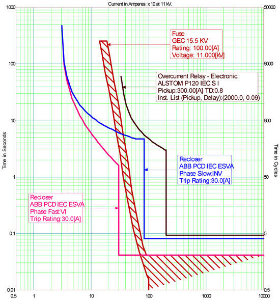
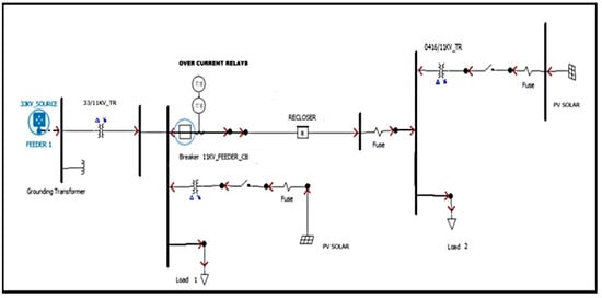
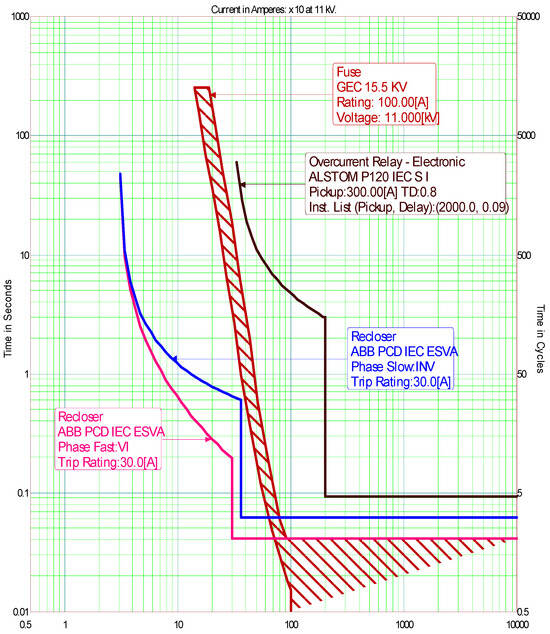
2.6. Coordination of PDs

Coordination is the selectivity in the PD setting to separate the abnormal part of the system only. Moreover, the development of a carefully considered design of basic elements in the protection systems of electrical DNs is critical to many industrial, healthcare, and continuous process systems. For this reason, coordination is an essential component of a complex electrical distribution protection system design [78][43]. The goal of protection coordination in DNs is discrimination to prevent degradation of the consistency of the RDS [79][44]. Generally, it involves fuses, reclosers, and overcurrent relays PDs. Proper coordination among these PDs means that there is no malfunction or duplication of their operation [80][45]. The immediate isolation of unhealthy parts of a DN altered by various permanent electric faults means the protection coordination system operated appropriately. Protection relay basic requirements are specifically defined as selectivity, speed, sensitivity, and reliability [81][46]. The typical coordination procedures between the circuit breaker (CB) with an overcurrent relay, recloser, and fuse at medium voltage 11 kV are illustrated in the model below, which shows RDNs. Figure 53 shows empirical examples of different cases.
Figure 53. Medium voltage 11 kV model in RDNs.

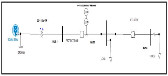
2.6.1. Over-Current Relay-Recloser-Fuse Coordination (without GDG)

The overcurrent relay setting should be precise and perfect to ensure fault sensitivity with high-reliability networks. Relay operation must be coordinated to achieve the desired selectivity and to minimize disruption to the operation when the fault is isolated. Coordination requires the adjustment of two important settings, the pickup current (Ip) and TDS [39][47]. According to the IEC standard, the operating time of an inverse time OCR and the fast and slow mode of a recloser can be calculated according to the following Equation (1):


where

where

𝑡_𝑜𝑝

is the relay operating time,

M

is the ratio of the fault current depending on the relay type of standard, and

L

is a constant. The pickup set current or

Ip

can be calculated with respect to the maximum load

𝐼𝐿 sensitivity by the relay as in (2) below:

sensitivity by the relay as in (2) below:


The time characteristics of overcurrent relays are generally nonlinear. This period may consider several factors, including CB trip time, tolerances for both CB and relay, maintenance processes, and CT slight saturation, whereas the permanent faults can be cleared by the fuses as primary protection. The familiar curve of the fuse characteristics is explained in (3) [56,82][48][49]:


where 𝑡𝑓 is the operating time of the fuse, 𝐼_𝑓𝑓 is the fault current passing through the fuse, and 𝑎 and b represent fuse constants. The operating time of the fuse is high depending on the b constant value.

Firstly, when the GDG does not connect, the OCR must be set and coordinated to operate conditionally on the location and magnitude of the fault. Therefore, short circuit analysis should be calculated to limit the main coordination conditions represented by the maximum and minimum fault levels. The PDs operate depending on some factors like the reliability of customer service, types of PDs used in the networks and their settings, voltage level, network configuration, and the level of different fault types. If the fault happens after the fuse (LOAD 2) network, all the PDs are sensitive to that fault, but the fuse will clear the fault at first because it is the nearest device to the fault location.
Figure 64 represents the coordination curves using IDMT characteristics between the OCR, recloser, and fuse at 11 kV-MVN. During network disturbances, the recloser fast curve, fuse, and the OCR sense the fault or a sudden increase in a load more than the load current (300 A). The delay time between the fast and slow recloser curves causes the fuse to complete its arcing time and clears that fault as primary protection.
Figure 64. Coordination curves using IDMT characteristics between the OCR, recloser, and fuse.
For the fuse-saving mode, there is a delay time between the fast and slow recloser curves to avoid a temporary fault because more than 70% of DNs are temporary faults [48][30]. Also, the recloser will operate as the first backup protection with a permanent fault when the fuse does not operate for any reason and clear the fault before the OCR operates.
Finally, the OCR operates as a secondary backup when both the primary and first backup protections fail to clear the disturbances in the RDN. In this scenario, the coordination of protective devices (PDs) is highly reliable and sensitive, ensuring the protection of electrical equipment. This sensitivity is particularly important during high short-circuit currents exceeding 1 kA, as it triggers the activation of the instantaneous feature.
Furthermore, if a fault occurs in the section of the feeder before the fuse location and after the recloser, a different scenario unfolds. In this situation, the coordination between the OCR and the recloser plays a crucial role in ensuring that the recloser clears the fault before the OCR comes into operation as the primary protection. Accordingly, the OCR operates as backup protection if the recloser slackens. Sometimes, the fault happens on the feeder section between the main CB and recloser (near LOAD 1), and in this case, the OCR will operate only to clear that fault within a specific set time.

2.6.2. Over-Current Relay-Recloser-Fuse Coordination (with a GDG)

Major protection problems related to the introduction of a GDG into DNs consist of protection blindness, false tripping, miscoordination of fuse reclosing, interfuse coordination failure, and failed automatic reclosing [63][50]. Connecting a GDG to the radial feeders containing such PDs causes several protection problems at once. The fault current detection by the recloser is controlled by the GDG and can lead to a detection problem at first. Secondly, the coordination setting between the relay and recloser or fuse and recloser can be lost, leading to selectivity problems [5][51]. Implemented in load changes, system topology, or generation level are used for the new relay settings to obtain optimal coordination. The objective function uses the sum of the TDS of primary relays [83,84][52][53]. Therefore, when PVs are connected to the same radial feeder as in Figure 75, the power flow will be in the opposite direction as well, and the fault current level and direction will be changed. The coordination curves need to be re-coordinated to ensure that all PDs will be operating.
Figure 75. Medium voltage 11 kV model in RDNs with PV solar.
Figure 86 illustrates the mal coordination between the relay, recloser, and fuse after connecting PV solar with the distribution feeder. Therefore, PDs should be re-coordinated to absorb the PV effect on the fault level during the network disturbance. The main implication is that the currents flowing through the relay, recloser, and fuse do not have the same characteristics when a fault occurs. The fault current may be increased or decreased depending on the fault current contribution from the GDG and the fault location and type, i.e., :


Figure 86. Coordination curves using IDMT characteristics between the OCR, recloser, and fuse with connected PV solar.
The protective system is structured to ensure that, when a fault occurs, a primary relay is designated to initiate isolation, and a supplementary group of backup relays is poised to act should the primary relay falter. The relay settings must be meticulously configured to prevent the backup relays from activating before the primary relay [85][54]. The use of inverters for feeding renewable energy is generated mainly by direct current like PV solar, and these inverters have internal protection so that protection against overload is provided by the control of current routing, and protection against short circuits is provided by fuses (internal).
This protection must be supplemented by external PDs to avoid damage to the inverter by the energy supplied by the grid (for AC) and by the source (for AC and DC) [77][42]. The integration of a GDG with this feeder type causes many protection problems. Firstly, the recloser fault current detection is influenced by the new power generation and may cause a fault detection problem. Secondly, it loses the coordination between reclosers or the fuse and recloser, which causes discrimination issues [86][55].
It is necessary to investigate the influences of GDG penetration into DNs to calculate the minimum operating time and determine coordination problems. These influences are derived from situations of both increases and decreases in the fault current [75][39].
It is necessary to maintain protection coordination when considering the future installation of PV systems with any penetration level and various locations in conjunction with the distribution power supply. Therefore, using the proposed strategies with offline calculations does not require communication links [60][56]. The authors in [87][57] improved the Protection Coordination Index (PCI) on interconnected DNs using the time–current–voltage feature set and dual configuration in DOCRs. IEEE 14- and 30-bus systems are used to illustrate the selectivity of overcurrent relays, which are imperative in active distribution systems with an increasing penetration level of GDGs.
Meanwhile, the same solution was used in [58], where the results show that a GDG connection with a mesh distribution system reduces the overall relay operating time by using a specific strategy. Substantiating an innovative dynamic and hybrid tripping approach designed to minimize tripping delays and enhance the coordination performance of OCR and EF relays was discussed in [88][59].
An optimization strategy was developed to minimize the TDS, FCT, and starting current for relay configuration by the Particle Swarm Optimization (PSO) algorithm. The analyses and assessment of the IEEE 14-bus system, compared with existing methods, showed the best validity of the minimum response time for the current transformer (CT) configuration. Therefore, it decreases the operating times of the relay and keeps the protection coordination between the OCRs applicable [37][27]. The DNs protection coordination problem with DOCRs was classified as a nonlinear mixed-intergeneration level programming problem (MINLP) and was solved using the well-established DE algorithm.
Using a sample system, the feasibility and effectiveness of the proposed method have been approved [81][46]. The time lapse between the operation of primary and backup protective devices is known as the CTI. It is calculated as the difference between the moment circuit breakers trip due to the primary protection and the operating time of the backup protection. A typical CTI is restricted between 0.2 to 0.5 s in practical applications concerning many factors like PDs over travel, CT faults and calibration, and fault current DC components [89][60].
The installation of a GDG can perturb the coordination of the protection system and therefore either some coordination changes or exhaustive replacement should be carried out of the PDs. The planning etiquette in existing distribution systems must be reviewed to consider the size, location, and penetration levels of DGs [21][8]. The SCC calculations for DNs containing renewable PV solar energy are proposed in [90][61].
The IEC60909 standard provides a convenient method for calculating short-circuit currents (SCC) in a standardized manner. Subsequently, the coordination process, based on the IEEE242 standard, is implemented when configuring the design and coordination of protection relays. All analyzed assessments are carried out in ETAP by simulating a short-circuit situation. An embedded GDG with RDN changes the topology to a multi-loop DN. Therefore, breakpoints are applied to the initial relays to find the OCR settings to regulate the starting point and defer conflicting constraints that reduce the CPU time [91][62].

References

  1. Ahmed, A.J.; Alkhafaji, M.H.; Mahdi, A.J. Performance Enhancement of a Low-Voltage Microgrid by Measuring the Optimal Size and Location of Distributed Generation. Acta IMEKO 2022, 11, 1–8.
  2. Barra, P.H.A.; Coury, D.V.; Fernandes, R.A.S. A Survey on Adaptive Protection of Microgrids and Distribution Systems with Distributed Generators. Renew. Sustain. Energy Rev. 2020, 118, 109524.
  3. Sorrentino, E.; Rodríguez, J.V. Effects of Fault Type and Pre-Fault Load Flow on Optimal Coordination of Directional Overcurrent Protections. Electr. Power Syst. Res. 2022, 213, 108685.
  4. Fani, B.; Bisheh, H.; Karami-horestani, A. An Offline Penetration-Free Protection Scheme for PV-Dominated Distribution Systems. Electr. Power Syst. Res. 2018, 157, 1–9.
  5. Dagar, A.; Gupta, P.; Niranjan, V. Microgrid Protection: A Comprehensive Review. Renew. Sustain. Energy Rev. 2021, 149, 111401.
  6. Sampaio, F.C.; Leão, R.P.S.; Sampaio, R.F.; Melo, L.S.; Barroso, G.C. A Multi-Agent-Based Integrated Self-Healing and Adaptive Protection System for Power Distribution Systems with Distributed Generation. Electr. Power Syst. Res. 2020, 188, 106525.
  7. Beheshtaein, S.; Cuzner, R.; Savaghebi, M.; Guerrero, J.M. Review on Microgrids Protection. IET Gener. Transm. Distrib. 2019, 13, 743–759.
  8. Abdel-Galil, T.K.; Ahmed, E.B.; Abu-Elanien, E.; El-Saadany, E.F.; Girgis, A.; Mohamed, Y.A.-R.I.; Salama, M.M.A.; Zeineldin, H.H.M. Protection Coordination Planning with Distributed Generation; Canmet Energy Technology Centre: Ottawa, QC, Canada, 2007.
  9. Rebollal, D.; Carpintero-rentería, M.; Santos-martín, D.; Chinchilla, M. Microgrid and Distributed Energy Resources Standards and Guidelines Review: Grid Connection and Operation Technical Requirements. Energies 2021, 14, 523.
  10. Lazarou, S.; Vita, V.; Ekonomou, L. Protection Schemes of Meshed Distribution Networks for Smart Grids and Electric Vehicles. Energies 2018, 11, 3106.
  11. Larik, N.A.; Li, M.S.; Jamali, J.A.; Wu, Q.H.; Ahmed, T. Islanding Issues, Consequences, and a Robust Detection Method for Hybrid Distributed Generation Based Power Systems. Eng. Technol. Appl. Sci. Res. 2023, 13, 11484–11489.
  12. Antonova, G.; Nardi, M.; Power, D.E.; Pesin, M. Distributed Generation and Its Impact on Power Grids and Microgrids Protection. In Proceedings of the 2012 65th Annual Conference for Protective Relay Engineers, College Station, TX, USA, 2–5 April 2012.
  13. Razavi, S.; Rahimi, E.; Sadegh, M.; Esmaeel, A. Impact of Distributed Generation on Protection and Voltage Regulation of Distribution Systems: A Review. Renew. Sustain. Energy Rev. 2019, 105, 157–167.
  14. Brearley, B.J.; Prabu, R.R. A Review on Issues and Approaches for Microgrid Protection. Renew. Sustain. Energy Rev. 2017, 67, 988–997.
  15. Chandra, A.; Singh, G.K.; Pant, V. Protection of AC Microgrid Integrated with Renewable Energy Sources—A Research Review and Future Trends. Electr. Power Syst. Res. 2021, 193, 107036.
  16. Mohammadi, P. Protection Challenges of Distributed Energy Resources Integration in Power Systems. Ph.D. Thesis, Louisiana State University, Baton Rouge, LA, USA, 2017.
  17. Ekanayake, J.; Strbac, G.; Jenkins, N. Distributed Generation; The Institution of Engineering and Technology: London, UK, 2010; ISBN 9780863419584.
  18. Chowdhury, S.; Chowdhury, S.P.; Crossley, P. Microgrids and Active Distribution Networks; The Institution of Engineering and Technology: London, UK, 2009; ISBN 9781849191029.
  19. Cheng, Y.; Liu, Y.; Zhang, Z.; Li, Y. An Asymmetric Encryption-Based Key Distribution Method for Wireless Sensor Networks. Sensors 2023, 23, 6460.
  20. Abbaspour, E.; Fani, B.; Heydarian-Forushani, E. A Bi-Level Multi Agent Based Protection Scheme for Distribution Networks with Distributed Generation. Int. J. Electr. Power Energy Syst. 2019, 112, 209–220.
  21. Tejeswini, M.V.; Jacob Raglend, I.; Yuvaraja, T.; Radha, B.N. An Advanced Protection Coordination Technique for Solar In-Feed Distribution Systems. Ain Shams Eng. J. 2019, 10, 379–388.
  22. Yousaf, M.; Muttaqi, K.M.; Sutanto, D. Assessment of Protective Device Sensitivity with Increasing Penetration of Distributed Energy Resources. In Proceedings of the Australasian Universities Power Engineering Conference, AUPEC 2018, Auckland, New Zealand, 27–30 November 2018; pp. 1–6.
  23. Stennikov, V.; Barakhtenko, E.; Mayorov, G.; Sokolov, D.; Zhou, B. Coordinated Management of Centralized and Distributed Generation in an Integrated Energy System Using a Multi-Agent Approach. Appl. Energy 2022, 309, 118487.
  24. Fayazi, H.; Fani, B.; Moazzami, M.; Shahgholian, G. An Offline Three-Level Protection Coordination Scheme for Distribution Systems Considering Transient Stability of Synchronous Distributed Generation. Int. J. Electr. Power Energy Syst. 2021, 131, 107069.
  25. Abbaspour, E.; Fani, B.; Sadeghkhani, I.; Alhelou, H.H. Multi-Agent System-Based Hierarchical Protection Scheme for Distribution Networks With High Penetration of Electronically-Coupled DGs. IEEE Access 2021, 9, 102998–103018.
  26. Hojjaty, M.; Fani, B.; Sadeghkhani, I. Intelligent Protection Coordination Restoration Strategy for Active Distribution Networks. IET Gener. Transm. Distrib. 2021, 16, 397–413.
  27. Ghanbari, M.; Gandomkar, M.; Nikoukar, J. Protection Coordination of Bidirectional Overcurrent Relays Using Developed Particle Swarm Optimi- Zation Approach Considering Distribution Generation Penetration and Fault Current Limiter Placement Coordination de La Protection Des Relais de Surintensité. IEEE Can. J. Electr. Comput. Eng. 2021, 44, 143–155.
  28. Hassan, A.S.; Sun, Y.; Wang, Z. Optimization Techniques Applied for Optimal Planning and Integration of Renewable Energy Sources Based on Distributed Generation: Recent Trends. Cogent Eng. 2020, 7, 1766394.
  29. Sahebi, A.; Askarian-Abyaneh, H.; Sadeghi, S.H.H.; Samet, H.; Malik, O.P. Efficient Practical Method for Differential Protection of Power Transformer in the Presence of the Fault Current Limiters. IET Gener. Transm. Distrib. 2023, 17, 3861–3871.
  30. Rizwan, M.; Hong, L.; Waseem, M.; Shu, W. Sustainable Protection Coordination in Presence of Distributed Generation with Distributed Network. Int. Trans. Electr. Energy Syst. 2020, 30, 1–23.
  31. Hatata, A.; Kaddah, S.; Abdraboh, H.; Frahat, M. Optimal Directional Overcurrent Relay Coordination Using Artificial Immune Algorithm. Bull. Fac. Eng. Mansoura Univ. 2014, 39, 9–18.
  32. Esobinenwu, C.S. Performance Evaluation of Overcurrent Relay in a Distribution Substation For Improved Protection and Coordination. SADI Int. J. Sci. Eng. Technol. 2023, 10, 12–24.
  33. Kennedy, J.; Ciufo, P.; Agalgaonkar, A. A Review of Protection Systems for Distribution Networks Embedded with Renewable Generation. Renew. Sustain. Energy Rev. 2016, 58, 1308–1317.
  34. Xu, L.; Li, K.; Yang, Z.; Jiang, X. Analysis of Discharge Failure Mechanism of IGBT Power Modules. Energies 2023, 16, 6001.
  35. Schneider Electric. Protection Relays Guide 2012; Schneider Electric: Rueil-Malmaison, France, 2012.
  36. Department of the Army. Coordinated Power Systems Protection 1991; Department of the Army: Arlington County, VA, USA, 1991.
  37. Ninad, N.; Natural, C.; Canada, R.; Turcotte, D.; Canada, N.R. DER Penetration Level Impact on the Protection of Distribution Systems. In Proceedings of the 2023 CIGRE Canada Conference & Exhibition, Vancouver, BC, Canada, 25–28 September 2023.
  38. Manditereza, P.T.; Bansal, R. Renewable Distributed Generation: The Hidden Challenges—A Review from the Protection Perspective. Renew. Sustain. Energy Rev. 2016, 58, 1457–1465.
  39. Fern, A. Impact of Distributed Generation on Distribution System. Master’s Thesis, Aalborg University, Arlington, TX, USA, 2011.
  40. Han, Z. Protection Coordination in Networks with Renewable Energy Sources. Master’s Thesis, University of Manchester, Manchester, UK, 2014.
  41. Gers, J.M.; Holmes, E.J. Protection of Electricity Distribution Networks; Institution of Electrical Engineers: London, UK, 2005.
  42. Gómez, J.C.; Vaschetti, J.; Piumetto, M.; Arcurio, J.; Coyos, C. Protection of Power Semiconductors in Inverters, Using Fuses and Their Coordination with the Protection Schemes of the Distribution System. In Proceedings of the 19th International Conference on Renewable Energies and Power Quality (ICREPQ’21), Almeria, Spain, 28–30 July 2021.
  43. Al Talaq, M.; Al-Muhaini, M. Chapter 5—Optimal Coordination of Time Delay Overcurrent Relays for Power Systems with Integrated Renewable Energy Sources. In Power System Protection in Future Smart Grids; Uwstun, T.S., Ed.; Academic Press: Cambridge, MA, USA, 2023; pp. 81–107. ISBN 978-0-323-91780-3.
  44. Al Talaq, M.; Al-Muhaini, M. Optimal Coordination of Time Delay Overcurrent Relays for Power Systems with Integrated Renewable Energy Sources. Energies 2022, 15, 6749.
  45. Industrial and Commercial Power Systems Standards Development Committee. IEEE Recommended Practice for Protection and Coordination of Industrial and Commercial Power Systems; IEEE: New York City, NY, USA, 2001; ISBN 0-7381-2844-9.
  46. Yang, H.; Wen, F.; Ledwich, G. Optimal Coordination of Overcurrent Relays in Distribution Systems with Distributed Generators Based on Differential Evolution Algorithm. Eur. Trans. Electr. Power 2011, 23, 1–12.
  47. Hatata, A.Y.; Ebeid, A.S.; El-Saadawi, M.M. Application of Resistive Super Conductor Fault Current Limiter for Protection of Grid-Connected DGs. Alexandria Eng. J. 2018, 57, 4229–4241.
  48. Farkhani, J.S.; Zareein, M.; Soroushmehr, H.; Sieee, H.M. Coordination of Directional Overcurrent Protection Relay for Distribution Network With Embedded DG. In Proceedings of the 2019 5th Conference on Knowledge Based Engineering and Innovation (KBEI), Tehran, Iran, 28 February –1 March 2019; pp. 281–286.
  49. Elbaset, A.A.; Mohamed, A.F.A.; El-Zahab, E.A.; Hassan, M.A.M. Recloser-Fuse Settings in Distribution Systems with Optimizing Multiple Distributed Generation Considering Technical Aspects. Indones. J. Electr. Eng. Comput. Sci. 2019, 17, 1135–1149.
  50. Saad, S.M.; El Naily, N.; Wafi, J.; Hussein, T.; Mohamed, F.A. An Optimized Proactive Over-Current Protection Scheme for Modern Distribution Grids Integrated with Distributed Generation Units. In Proceedings of the 2018 9th International Renewable Energy Congress (IREC), Hammamet, Tunisia, 20–22 March 2018; pp. 1–6.
  51. Coster, E.J. Distribution Grid Operation Including Distributed Generation. Ph.D. Thesis, Eindhoven University of Technology, Eindhoven, The Netherlands, 2010.
  52. Abdelaziz, A.Y.; Talaat, H.E.A.; Nosseir, A.I.; Hajjar, A.A. An Adaptive Protection Scheme for Optimal Coordination of Overcurrent Relays. Electr. Power Syst. Res. 2002, 61, 1–9.
  53. Nikolaidis, V.C.; Desiniotis, D.; Papaspiliotopoulos, V.A.; Tsimtsios, A.M.; Korres, G.N. Optimal Recloser-Fuse and Distribution Network Protection Coordination Including Distributed Generation Relays. In Proceedings of the 2022 International Conference on Smart Energy Systems and Technologies (SEST), Eindhoven, The Netherlands, 5–7 September 2022.
  54. Guimarães, M.M.; Takahashi, R.H.C.; Costa, M.H.; Moia, C.H.U.; Carrano, E.G. Robust Coordination of Overcurrent Relays for Several Simultaneous Faults in Wind Power Generation Systems. Appl. Soft Comput. 2023, 147, 110795.
  55. Coster, E. Effect of DG on Distribution Grid Protection. In Distributed Generation; Eindhoven University of Technology: Eindhoven, The Netherlands, 2010; pp. 95–118.
  56. Fani, B.; Bisheh, H.; Sadeghkhani, I. Protection Coordination Scheme for Distribution Networks with High Penetration of Photovoltaic Generators. IET Gener. Transm. Distrib. 2018, 12, 1802–1814.
  57. Dadfar, S.; Gandomkar, M. Augmenting Protection Coordination Index in Interconnected Distribution Electrical Grids: Optimal Dual Characteristic Using Numerical Relays. Int. J. Electr. Power Energy Syst. 2021, 131, 107107.
  58. Sharaf, H.M.; Zeineldin, H.H.; Ibrahim, D.K.; Essam, E.L. A Proposed Coordination Strategy for Meshed Distribution Systems with DG Considering User-Defined Characteristics of Directional Inverse Time Overcurrent Relays. Int. J. Electr. Power Energy Syst. 2015, 65, 49–58.
  59. Alasali, F.; Saidi, A.S.; El-Naily, N.; Alnaser, S.W.; Holderbaum, W.; Saad, S.M.; Gamaleldin, M. Advanced Coordination Method for Overcurrent Protection Relays Using New Hybrid and Dynamic Tripping Characteristics for Microgrid. IEEE Access 2022, 10, 127377–127396.
  60. Glover, D.; Sarma, M.; Overbye, T. Power System Analysis and Design; Wadsworth/Thomson Learning: Belmont, CA, USA, 2012; Volume 53, ISBN 978-1-111-42579-1.
  61. Khattijit, N.; Oranpiroj, K.; Muangjai, W. The Evaluation of Short Circuit Current to Achieve Optimal Design and Protection for Elements in Power Network with Renewable Energy. In Proceedings of the 2018 International Electrical Engineering Congress (iEECON), Krabi, Thailand, 7–9 March 2018; pp. 1–4.
  62. Meskin, M.; Domijan, A.; Grinberg, I. Optimal Co-Ordination of Overcurrent Relays in the Interconnected Power Systems Using Break Points. Electr. Power Syst. Res. 2017, 127, 53–63.
More
Video Production Service