Space weather in terms of low earth orbits has been characterized into seven main elements, namely microgravity, residual atmosphere, high vacuum, atomic oxygen, ultraviolet and ionization radiation, solar radiation, and space debris. Each element effects on polymers and composite materials. Quantification of these effects can be evaluated by understanding the mechanisms of material degradation caused by each environmental factor along with its synergetic effect. Hence, the design elements to mitigate the material degradation can be identified. Finally, a cause-and-effect diagram (Ishikawa diagram) is designed to characterize the important design elements required to investigate while choosing a material for a satellite’s structure. This will help the designers to develop experimental methodologies to test the composite material for its suitability against the space environment. Some available testing facilities will be discussed. Some potential polymers will also be suggested for further evaluation.
- low earth orbit environmental exposure
- material degradation
- composite material
- space debris
1. Introduction
Low Earth orbit (LEO) is closest to the Earth at an altitude of 160 km (thermosphere) to 1000 km. The International Space Station (ISS) orbits at 400 km in this region. Satellites are also launched in this region. The time period of a satellite for one circumnavigation of the earth in this orbit is approximately 90 min. These satellites generally perform tasks like telecommunication, science exploration etc. Low earth orbit is actually the part of the earth’s atmosphere with very few air molecules in the form of ions and minimal gravity. Solar radiation ionizes the gases in the atmosphere from 50 km to 965 km, which overlaps mesosphere and thermosphere. Gases stay in the form of ions rather than in molecules, for example, oxygen, hydrogen, helium ions, etc. Aurora light occurs in this region due to the presence of ions, magnetic storms and solar winds. The environment of the orbit varies with altitude. Hence, the material degradation phenomenon and design strategies for space structures also vary. Therefore, to select a suitable material for low earth orbit, the LEO environment and its effect on the material must be studied thoroughly. The LEO environment can be categorized into seven sub-categories, according to the NASA researcher guide [1].
2. High Proximity to the Earth
3. Residual Atmosphere
4. High Vacuum
5. High Thermal Cycling
-
Direct sunlight;
-
Its view to the sun, i.e., sun side or shadow side;
-
Reflected sunlight from earth (Albedo);
-
Position of the earth with respect to the sun, i.e., aphelion or perihelion and position of the satellite with respect to the earth, i.e., perigee and apogee;Infrared radiation from Earth;
-
Internal heat produced by satellite component.
- Its view to the earth, i.e., earth’s shadow or earth-facing.

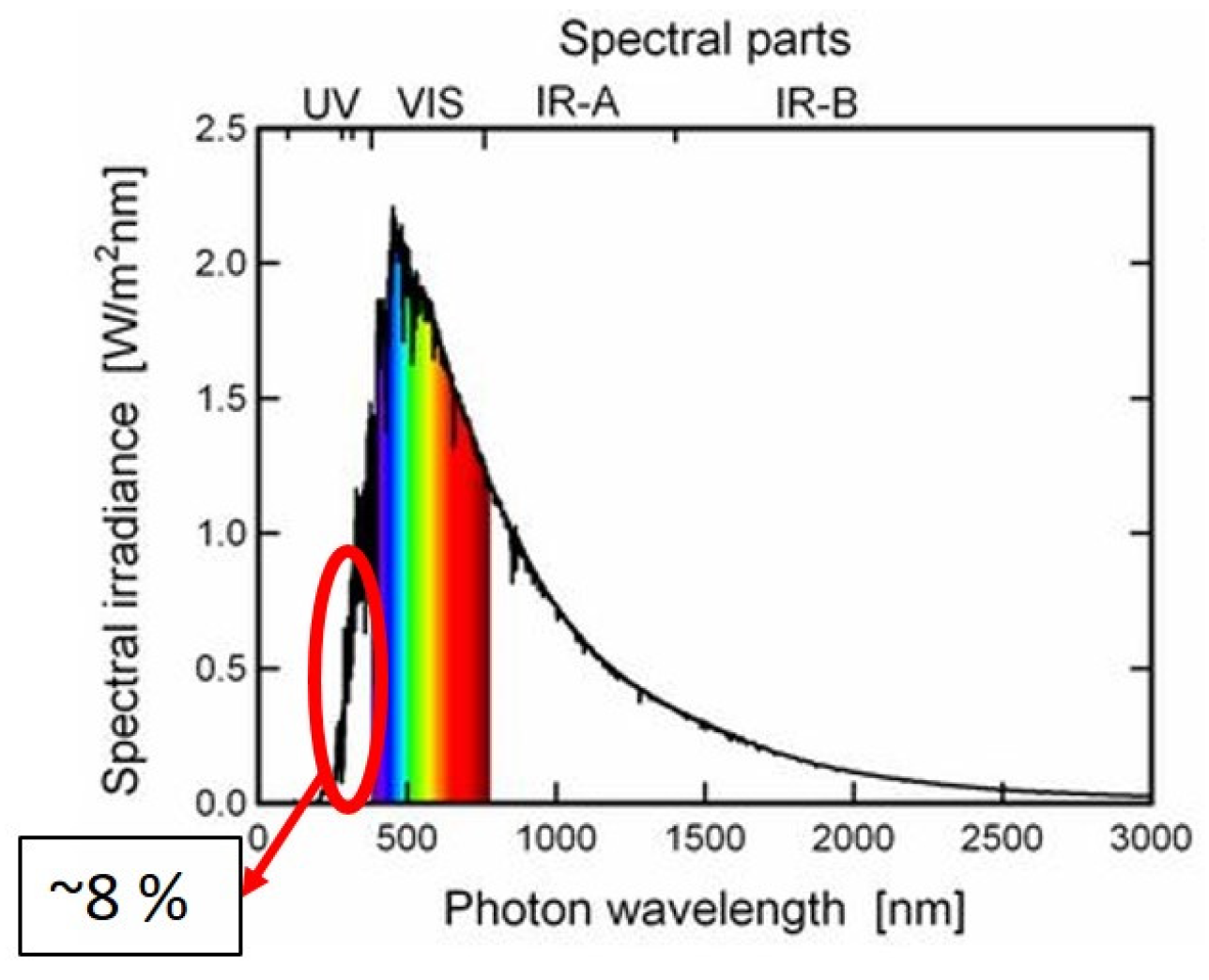
6. Ultra-Violet and Ionization Radiation
-
Material discoloration occurs due to the absorption of UV rays. The surface color of the material gets yellowed or dark. The polymer absorbs UV rays and undergoes several chemical reactions, such as dissociation of bonds, isomerization, free radical polymerization and contamination or recombination with other free radicals. This changes the mechanical properties of the structure.
-
It erodes the surface, which increases the surface roughness. Discoloration, in addition to surface roughness, deteriorates the thermo-optical properties, which decreases the efficiency of the thermal control surface. Hence, low solar absorption and high thermal emittance are required in the material to reduce this phenomenon.
-
The polymeric chain is de- and re-associated. Such cross-linking modifies the chemical structure of the polymer. Such modification leads to loss of mechanical, optical and chemical properties [11][23][24][25][26][27][28][29]. The polymeric chain with aromatic rings or phenyl rings may have higher erosion compared to polymers having long polymeric chains [30]. Aromatic rings or phenyl groups have more C=C bonds, which makes them stronger UV absorbents. Thus, there is a higher chance of chain scissioning and polymer fragmentation.
-
Polymers undergo embrittlement or chain scission in which polymeric bonds de-associate from polymeric chains and perform bonds with free ions. This free radical polymerization creates volatiles, which sublimate in the space. This phenomenon erodes the surface. The presence of a high vacuum increases this erosion even further. Reactive functional groups in the polymer chain sublimate faster in the environment [30].
-
Changes in the chemical structure of the polymer degrades the viscoelastic properties. UV radiation increases the glass transition temperature of epoxy-based shape memory polymer by 2.9% after exposition to UV radiation with a wavelength of 250–400 nm for 80 h [11]. It also increases the stiffness of the material by 41% after 80 hours of exposure. However, 80 h of exposure is too short to conclude the variation of glass transition temperature and stiffness. Hence, more polymers and longer exposure times are required for the investigation.
7. Atomic Oxygen
-
Change in the chemical composition of the polymer, which leads to loss of mechanical properties;
-
Embrittlement and chain scission of polymeric chains;
-
Material erosion, which leads to loss of material, hence creates dimensional instability;
-
Loss of thermo-optical properties of the material (i.e., absorptance and emittance) due to material discoloration.
8. Space Debris
9. Conclusion
Even though polymers have been used since the beginning of the space age as polymer thin films in protective layers, coating, insulation, space suits, etc., researchers have limited material data. Since 2000, the new space age industries have focused more on reducing weight. They have already listed the benefits of composite structures in space. Nowadays, composite materials are used in space structures such as antennas, hinges, morphing wings, booms, solar arrays, struts and trusses, frames of satellites, battery casings, holding cases of satellite equipment like lenses, sensors, thrusters, reaction wheels, cameras, etc. Surprisingly, these composite parts are launched into space without a thorough examination of material data dependent on the space environmental conditions. Space regulations for cube satellites are also relaxed compared to those for large satellites. One possible reason behind this could be a lack of assessment of the risk factors that could lead to catastrophic failures of the satellites. Material erosion and degradation due to long-term exposure are not well understood, and there is a lack of data on material performance in relation to space environmental factors.
Studying material degradation in the space environment has many challenges. The initial challenge is to develop testing chambers equivalent to the orbit environment, which can replicate approximately vacuum, radiation and thermal cycles experienced in the orbit. Very few institutions have these facilities, but they are mostly in separate chambers situated in different locations. The costs and time required to obtain experimental data from these specialized chambers are significant, which further extends project durations and costs. Synergetic climatic chambers that combine multiple environmental factors could be a valuable addition, which not only reduces the time but also improves the accuracy of material data, as a synergetic environment is more detrimental to material degradation. However, it is a second challenge to combine all the factors of the orbit environment in one chamber, even with modern technology. The third challenge is to accelerate the process so that long-term material data could be generated in the shortest time period and at the lowest cost.
The synergistic effects of the LEO environment, including electron/proton and ultraviolet radiation combined with atomic oxygen and thermal cycling, can significantly accelerate mass erosion compared to individual factors. For example, the double-sided aluminized Kapton thermal blanket used in the ISS was completely damaged after one year of exposure even though the expected lifetime was 15 years, based on ground laboratory tests in which the specimen was irradiated by atomic oxygen with fluence level equivalent to 15 years [68,71]. The erosion rate of Kapton film in space (in orbit of the ISS) was 18 times higher than the results obtained in a ground test facility on Earth [2]. Therefore, material degradation should be investigated thoroughly for more polymer and composite materials. A comprehensive material database should be provided to the designers to create a responsible space structure that will not fail during the functional life of the satellite as well as does not stay longer in space as space debris.
References
- Finckenor, M.M.; Groh, K.K.D. Reseacher’s Guide to ISS: Space Environmental Effects; NASA: Washington, DC, USA, 2015.
- Sarantinos, N.; Loginos, P.; Charlaftis, P.; Argyropoulos, A.; Filinis, A.; Vrettos, K.; Adamos, L.; Kostopoulos, V. Behavior of photopolymer fiber structures in microgravity. SN Appl. Sci. 2019, 1, 1693.
- Banks, B.A.; Miller, K.R.S. Overview of Space Environment Effects on Materials and GRC’s Test Capabilities. In Proceedings of the 2005 NASA Seal/Secondary Air System Workshop, Cleveland, OH, USA, 8–9 November 2005; Glenn Research Center: Sandusky, OH, USA NASA/CP—2006-214383/VOL1.
- Banks, B.A. Atomic Oxygen. In Proceedings of the LDEF Materials Data Analysis Workshop, Merritt Island, FL, USA, 13–14 February 1990; p. 290.
- Samwel, S.W. Low Earth Orbital Atomic Oxygen Erosion Effect on Spacecraft Materials. Space Res. J. 2014, 7, 1–13.
- Walter, N.A.; Scialdone, J. Outgassing Data for Selecting Spacecraft Materials; NASA Reference Publication 1124; NASA: Washington, DC, USA, 1997; 444p.
- Anwar, A.; Elfiky, D.; Hassan, G.; Albona, M.; Marchetti, M. Outgassing Effect on Spacecraft Structure Materials. Int. J. Astron. Astrophys. Space Sci. 2015, 2, 34–38.
- Tribble, A.C. Designing for the space environment. Aerosp. Am. 1993, 31, 26–29.
- Maini, A.K.; Agrawal, V. Satellite Technology: Principles and Applications, 3rd ed.; Wiley: Chichester, WS, USA, 2014; ISBN 978-1-118-63647-3.
- Gao, Y.; He, S.; Yang, D.; Liu, Y.; Li, Z. Effect of vacuum thermo-cycling on physical properties of unidirectional M40J/AG-80 composites. Compos. Part B: Eng. 2005, 36, 351–358.
- Tan, Q.; Li, F.; Liu, L.; Liu, Y.; Yan, X.; Leng, J. Study of low earth orbit ultraviolet radiation and vacuum thermal cycling environment effects on epoxy-based shape memory polymer. J. Intell. Mater. Syst. Struct. 2019, 30, 2688–2696.
- Mahdavi, S. Thermal Cycling of Out-of-Autoclave Thermosetting Composite Materials. Master’s Thesis, Concordia University, Montreal, QC, Canada, 2017.
- Hegde, S.R.; Hojjati, M. Effect of Thermal Cycling on Composite Honeycomb Sandwich Structures for Space Applications; ASTRO Cancadian Aeronautics and Space Institute: Montréal, QC, Canada, 2018; p. 7.
- Gao, Y.; Dong, S.L.; Wang, H.S.; Lu, S.W.; Bao, J.W. Effect of Vacuum Thermal Cycling on Mechanical and Physical Properties of an Epoxy Matrix Composite. Adv. Mater. Res. 2011, 415–417, 2236–2239.
- Park, S.Y.; Choi, H.S.; Choi, W.J.; Kwon, H. Effect of vacuum thermal cyclic exposures on unidirectional carbon fiber/epoxy composites for low earth orbit space applications. Compos. Part B Eng. 2012, 43, 726–738.
- Shimokawa, T.; Katoh, H.; Hamaguchi, Y.; Sanbongi, S.; Mizuno, H.; Nakamura, H.; Asagumo, R.; Tamura, H. Effect of Thermal Cycling on Microcracking and Strength Degradation of High-Temperature Polymer Composite Materials for Use in Next-Generation SST Structures. J. Compos. Mater. 2002, 36, 885–895.
- Abdullah, F.; Okuyama, K.; Tapia, I.F. In-Situ Monitoring of Carbon Fiber/Polyether Ether Ketone (CF/PEEK) Composite Thermal Expansion in Low Earth Orbit. In Proceedings of the 8th International Symposium on Space Technology and Science, Tokyo, Japan, 17–21 June 2019.
- Lukez, R. The Use of Graphite/Epoxy Composite Structures in Space Applications; DigitalCommons@USU: Logan, UT, USA, 1987; p. 11.
- The Extraterrestrial (AM0) Solar Spectrum. Available online: https://www2.pvlighthouse.com.au/resources/courses/altermatt/The%20Solar%20Spectrum/The%20extraterrestrial%20%28AM0%29%20solar%20spectrum.aspx (accessed on 22 March 2023).
- ASTM E490-00a(2019); E21 Committee Standard Solar Constant and Zero Air Mass Solar Spectral Irradiance Tables. ASTM International: West Conshohocken, PA, USA, 2019.
- Yu-Ran Luo Bond Dissociation Energies 2010. Available online: http://staff.ustc.edu.cn/~luo971/2010-91-CRC-BDEs-Tables.pdf (accessed on 22 April 2021).
- ASTM E512-94(2020); E21 Committee ASTM E512 Practice for Combined, Simulated Space Environment Testing of Thermal Control Materials with Electromagnetic and Particulate Radiation. ASTM International: West Conshohocken, PA, USA, 2020.
- Dever, J.; Bruckner, E.; Rodriguez, E. Synergistic effects of ultraviolet radiation, thermal cycling and atomic oxygen on altered and coated Kapton surfaces. In Proceedings of the 30th Aerospace Sciences Meeting and Exhibit, Reno, NV, USA, 6–9 January 1992; American Institute of Aeronautics and Astronautics: Reston, VA, USA, 1992.
- Liau, W.B.; Tseng, F.P. The effect of long-term ultraviolet light irradiation on polymer matrix composites. Polym. Compos. 1998, 19, 440–445.
- Groh, K.K.D.; Smith, D.C. Investigation of Teflon FEP Embrittlement on Spacecraft in Low Earth Orbit; NASA Lewis Research Center: Cleveland, OH, USA, 1997.
- Ishizawa, J.; Mori, K. Space Environment Effects on Cross-linked ETFE Polymer. In Proceedings of the International Symposium on Materials in a Space Environment, Aix-en-Provence, France, 15–18 September 2009; p. 5.
- Grossman, E.; Gouzman, I. Space environment effects on polymers in low earth orbit. Nucl. Instrum. Methods Phys. Res. Sect. B Beam Interact. Mater. At. 2003, 208, 48–57.
- Awaja, F.; Moon, J.B.; Zhang, S.; Gilbert, M.; Kim, C.G.; Pigram, P.J. Surface molecular degradation of 3D glass polymer composite under low earth orbit simulated space environment. Polym. Degrad. Stab. 2010, 95, 987–996.
- Sznajder, M.; Renger, T.; Witzke, A.; Geppert, U.; Thornagel, R. Design and performance of a vacuum-UV simulator for material testing under space conditions. Adv. Space Res. 2013, 52, 1993–2005.
- Suliga, A. Resistance of CFRP Structures to Environmental Degradation in Low Earth Orbit. Ph.D. Thesis, University of Surrey, Guildford, UK, 2017.
- Bitetti, G.; Marchetti, M.; Mileti, S.; Valente, F.; Scaglione, S. Degradation of the surfaces exposed to the space environment. Acta Astronaut. 2007, 60, 166–174.
- De Groh, K.K.; Banks, B.A.; Mccarthy, C.E.; Rucker, R.N.; Roberts, L.M.; Berger, L.A. MISSE 2 PEACE Polymers Atomic Oxygen Erosion Experiment on the International Space Station. High Perform. Polym. 2008, 20, 388–409.
- Dooling, D.; Finckenor, M.M. Material Selection Guidelines to Limit Atomic Oxygen Effects on Spacecraft Surfaces; NASA Marshall Space Flight Center: Huntsville, AL, USA, 1999; p. 50. Available online: https://s3vi.ndc.nasa.gov/ssri-kb/static/resources/19990064119.pdf (accessed on 7 December 2021).
- Miller, S.K.R.; Banks, B. Degradation of Spacecraft Materials in the Space Environment. MRS Bull. 2010, 35, 20–24.
- Cool, G.R. Atomic Oxygen Erosion Resistance of Organic Polymers for Low Earth Orbit Spacecraft; National Library of Canada-Bibliothèque Nationale du Canada: Ottawa, ON, Canada, 1996.
- Devapal, D.; Packirisamy, S.; Korulla, R.M.; Ninan, K.N. Atomic oxygen resistant coating from poly(tetramethyldisilylene-co-styrene). J. Appl. Polym. Sci. 2004, 94, 2368–2375.
- Banks, B.A.; Backus, J.A.; Manno, M.V.; Waters, D.L.; Cameron, K.C.; Groh, K.K.D. Atomic Oxygen Erosion Yield Prediction for Spacecraft Polymers in Low Earth Orbit. In Proceedings of the 11th International Symposium on Materials in a Space Environment (ISMSE) 2009, Symposium and Exhibition NASA/TM--2002-211360, Aix en Provence, France, 15–18 September 2009.
- Banks, B.A.; Demko, R. Atomic Oxygen Protection of Materials in Low Earth Orbit. In Proceedings of the 2002 Symposium and Exhibition NASA/TM--2002-211360; Long Beach, CA, USA, 12–16 May 2002. Available online: http://gltrs.grc.nasa.gov/GLTRS (accessed on 5 June 2023).
- Kessler, D.J.; Johnson, N.L. The Kessler Syndrome: Implications to Future Space Operations. In Proceedings of the 33rd Annual AAS Guidance and Control Conference, Breckenridge, CO, USA, 6–10 February 2010.
- ESA UNOOSA ESA and UNOOSA Illustrate Space Debris Problem. Available online: https://www.esa.int/Safety_Security/Space_Debris/ESA_and_UNOOSA_illustrate_space_debris_problem (accessed on 18 May 2022).
- Self-cremating Satellite: A solution to reduce lifetime of space debris. In Proceedings of the European Interparliamentary Space Conference (EISC), Paris, France, 16 September 2022.
- EuroConsult. Prospects for Small Satellite Market Forecasts to 2029; EuroConsult: Washington, DC, USA, 2020; p. 7.
- Palla, C.; Kingston, J. Forecast analysis on satellites that need de-orbit technologies: Future scenarios for passive de-orbit devices. CEAS Space J 2016, 8, 191–200.
- TEC-QI, ESA. ESA Requirements on_End of Life to De-orbit. In Proceedings of the Technical Day on De-Orbit Strategies, Noordwijk, The Netherlands, 17 March 2015.
- ESA. ESA Technology Strategy 2019+; European Space Agency: Paris, France, 2019; p. 74.
- ESA Space Debris Office. ESA’s Annual Space Environment Report; ESA Space Debris Office; European Space Agency: Paris, France, 2020; GEN-DB-LOG-00288-OPS-SD.
- Flegel, S.K. Multi-layer insulation model for MASTER-2009. Acta Astronaut. 2011, 69, 911–922.
- Mejía-Kaiser, M. Collision Course: The 2009 Iridium -Cosmos Crash. In Proceedings of the 52nd Colloquium on the Law if Outer Space, Daejeon, Korea, 12 October 2009; Volume E8.3.9, p. 11. Available online: https://ssrn.com/abstract=3350010 (accessed on 7 December 2021).
- Walker, R.; Martin, C.; Strokes, H.; Wilkinson, J.; Sdunnus, H.; Hauptmann, S.; Beltrami, P.; Klinkrad, H. Update of the ESA Space Debris Mitigation Handbook; ESA: Paris, France, 2002.
- Dorey, G.; Bishop, S.M.; Curtis, P.T. On the Impact Performance of Carbon Fibre Laminates with Epoxy and PEEK Matrices. Compos. Sci. Technol. 1985, 23, 221–237.
- Graves, M.; Koontz, J. Initiation and extent of impact damage in graphite/epoxy and graphite/PEEK composites. In Proceedings of the 29th Structures, Structural Dynamics and Materials Conference, Williamsburg, VA, USA, 18–20 April 1988; American Institute of Aeronautics and Astronautics: Reston, VA, USA, 1988.
- Braid-Enhanced Composite Overwrapped Pressure Vessels |A&P Technology. Available online: https://www.braider.com/Case-Studies/Braid-Enhanced-Composite-Overwrapped-Pressure-Vessels.aspx (accessed on 7 December 2021).
- Kelkar, A.D.; Whitcomb, J.D. Characterization and Structural Behavior of Braided Composites; U.S. Department of Transportation: Washington, DC, USA, 2009.
- Malhotra, A.; Guild, F.J. Impact Damage to Composite Laminates: Effect of Impact Location. Appl. Compos. Mater. 2014, 21, 165–177.
- Metzner, C.; Gessler, A.; Weimer, C.; Beier, U.; Middendorf, P. Performance assessment on unidirectional braided CFRP materials. In Proceedings of the Low cost Composite Processing, from Aerospace OOA to Automotive Thermoplastics, Paris, France, 10–11 March 2014; SAMPE Europe: Paris, France, 2014.