Lithium-ion batteries (LIBs) have recently become popular for energy storage due to their high energy density, storage capacity, and long-term cycle life. Although binders make up only a small proportion of LIBs, they have become the key to promoting the transformation of the battery preparation process. Along with the development of binders, the battery manufacturing process has evolved from the conventional slurry-casting (SC) process to a more attractive solvent-free (SF) method. Compared with traditional LIBs manufacturing method, the SF method could dramatically reduce and increase the energy density due to the reduced preparation steps and enhanced electrode loading. Polytetrafluoroethylene (PTFE), as a typical binder, has played an important role in fabricating high-performance LIBs, particularly in regards to the SF technique.
- lithium-ion battery (LIBs)
- polymer binder
- solvent-free (SF) procedure
- polytetrafluoroethylene (PTFE)
1. Introduction
2. Developments in SF Processes and Binders
2.1. SF Processes
With the progressive realization of the significant advantages of the SF process, various SF electrode processes have evolved and have been employed in the fabrication of LIBs. As shown in Figure 31a–f, there are six typical SF electrode manufacturing processes: dry spraying deposition [11[11][16][17],27,33], vapor deposition [34[18][19],35], melting and extrusion [36][20], 3D printing [37[21][22],38], direct pressing [39,40][23][24], and polymer fibrillation [41,42,43][25][26][27].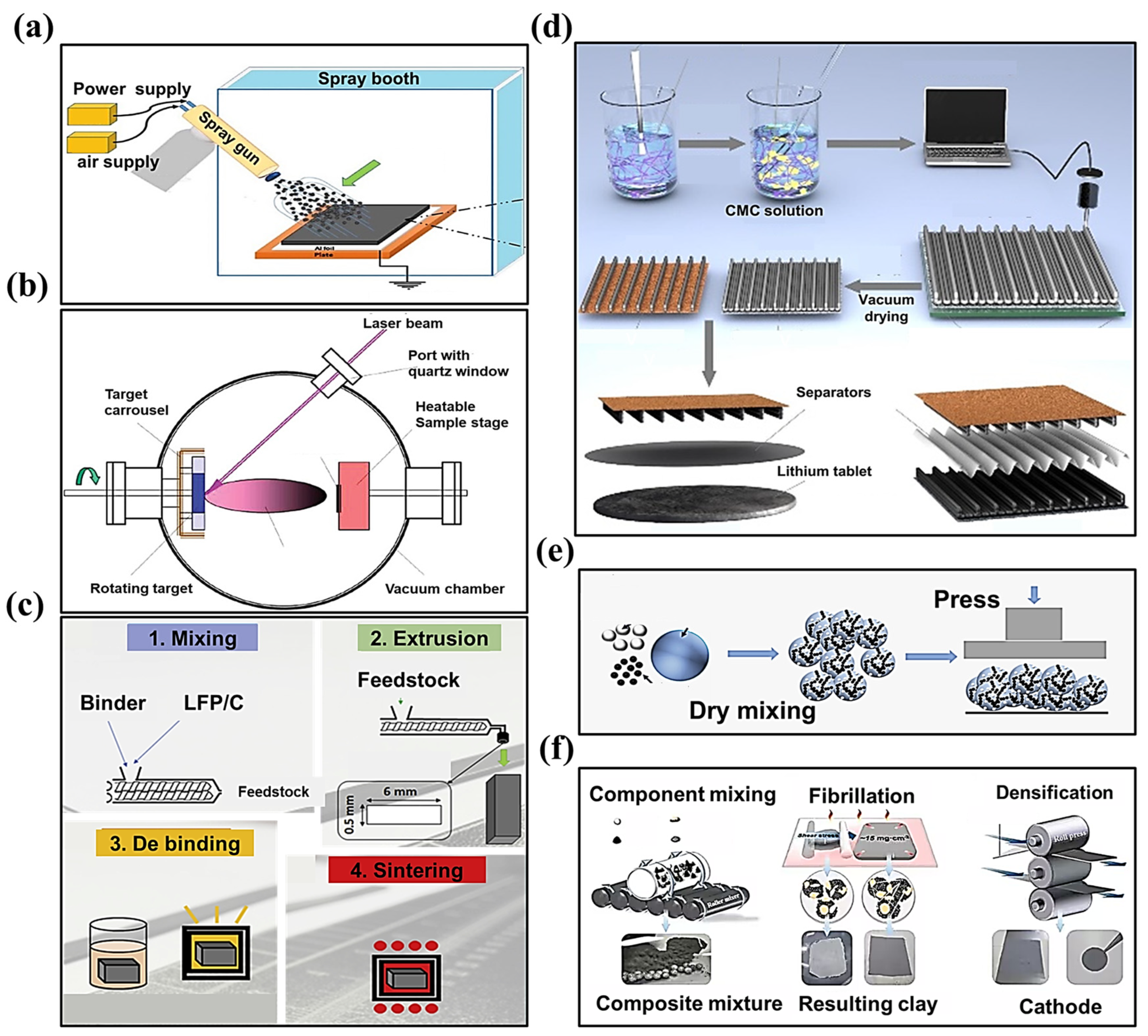
- I.
-
Dry spray depositionAs shown in Figure 31a, the method involves the dry mixing of the active material and the conductive agent first; then, the composite powder obtained is added to the spraying device. The composite powder (active material, conductive agent, binder) is sprayed onto the collector through the spraying device and then reinforced using the heat pressing method. For this method, the PVDF binder, or PVDF binder with a certain percentage of PTFE added, are commonly used [31][28].
- II.
-
Vapor deposition
- III.
-
Melting and extrusion
- IV.
-
3D printing
- V.
-
Direct pressing
- VI.
-
Polymer fibrillation
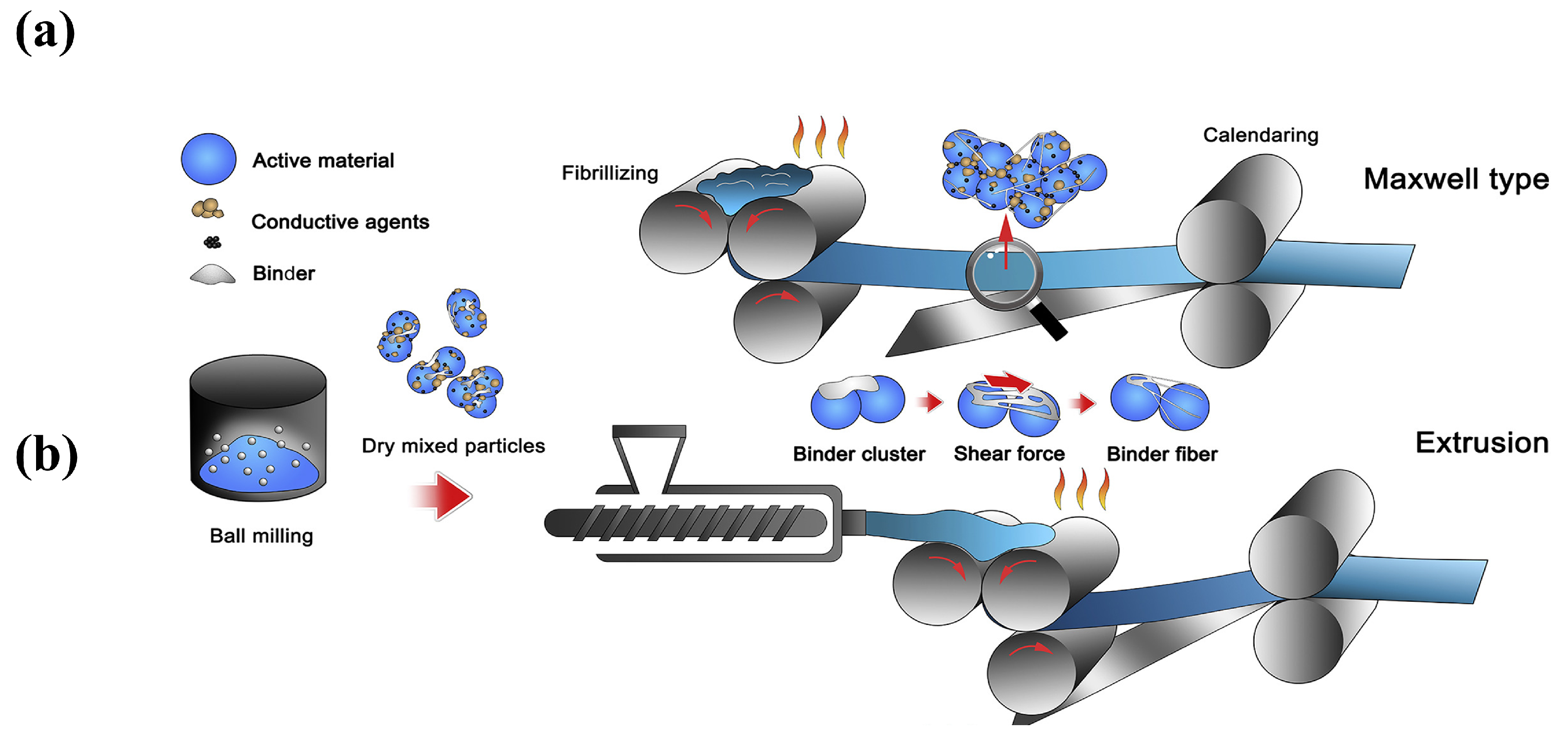 Figure 52.Processes of (a) powder extrusion molding, and (b) powder roll molding [45].
2.2. Binders
Actually, the SF process shows a tight relationship with the binder. The battery binder is a class of polymer compounds that adheres the active materials and conductive agents in the electrode sheet to the electrode collector, and it is one of the essential constituent materials of LIBs [13,46]. Although the amount of binder is small (∼5 wt%) [47], it serves to enhance the contact between the active material, the conductive agent, and the collector, as well as to stabilize the structure of the electrode sheet, which determines the change of the fabrication technology. Typical binders used in LIBs electrodes include PVDF [48,49,50,51,52,53], PTFE, styrene-butadiene rubber (SBR) [54,55,56], sodium carboxymethylcellulose (CMC) [57,58,59], poly (acrylic acid) (PAA) [60,61], poly (ethylene oxide) (PEO) [62,63,64], alginate [65,66,67], etc.In 2023, Tian Qin et al. [68] summarized the adhesion, tensile strength, elasticity, swelling, conductivity, thermal stability, and oxidation stability of seven types of binders. Among them, PVDF, as the major binder for commercial battery systems (cathode), shows the most satisfactory balance between the material and electrochemical properties, as shown in) powder roll molding [29].2.2. Binders
Actually, the SF process shows a tight relationship with the binder. The battery binder is a class of polymer compounds that adheres the active materials and conductive agents in the electrode sheet to the electrode collector, and it is one of the essential constituent materials of LIBs [13][30]. Although the amount of binder is small (∼5 wt%) [31], it serves to enhance the contact between the active material, the conductive agent, and the collector, as well as to stabilize the structure of the electrode sheet, which determines the change of the fabrication technology. Typical binders used in LIBs electrodes include PVDF [32][33][34][35][36][37], PTFE, styrene-butadiene rubber (SBR) [38][39][40], sodium carboxymethylcellulose (CMC) [41][42][43], poly (acrylic acid) (PAA) [44][45], poly (ethylene oxide) (PEO) [46][47][48], alginate [49][50][51], etc.In 2023, Tian Qin et al. [52] summarized the adhesion, tensile strength, elasticity, swelling, conductivity, thermal stability, and oxidation stability of seven types of binders. Among them, PVDF, as the major binder for commercial battery systems (cathode), shows the most satisfactory balance between the material and electrochemical properties, as shown inFigure 6.3.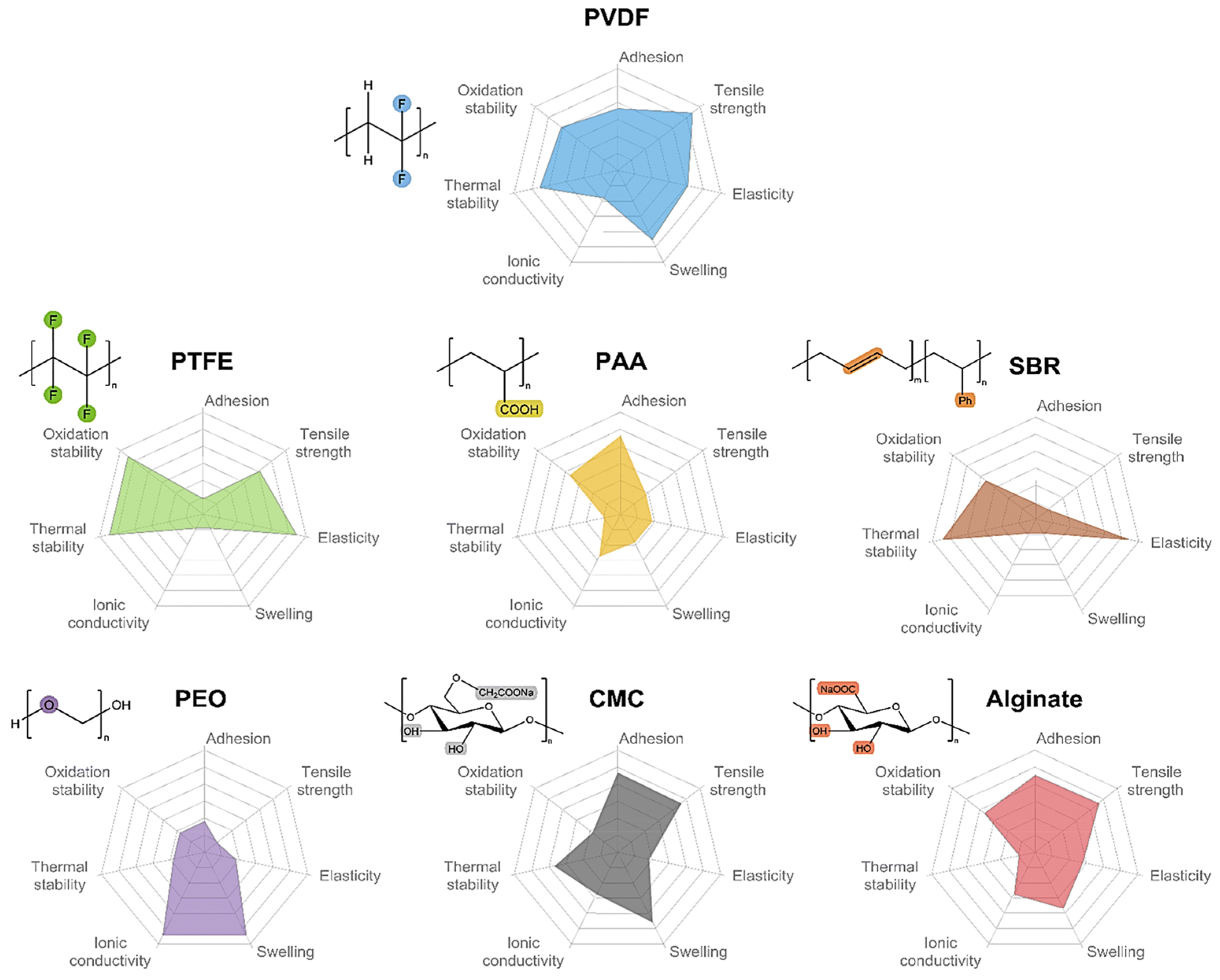 Figure 63. Comparison of the basic properties of common binders.The mechanical properties of CMC, PAA, and alginate are inferior to those of PVDF; however, they are rich in polar groups such as carboxylic or hydroxyl groups. The free carboxylic acid groups are able to interact with the hydroxyl groups on the surface of materials such as silicon/carbon and aluminum foils, resulting in better bonding properties. Even though CMC is inexpensive and thermally stable, it exhibits high rigidity and brittleness. In order to resolve these issues, CMC is often used as an anode binder in conjunction with SBR, which has high elasticity. The silicon anode with the SBR-CMC composite binder showed a smaller Young’s modulus and stronger adhesion strength to the collector [69]. PTFE, SBR, CMC, PAA, etc., could be used with water as a solvent to reduce the toxicity associated with the use of organic solvents, whereas further optimization of the time-consuming and energy-consuming drying step is still necessary in order to decrease the cost of battery manufacturing.The mechanical properties of CMC, PAA, and alginate are inferior to those of PVDF; however, they are rich in polar groups such as carboxylic or hydroxyl groups. The free carboxylic acid groups are able to interact with the hydroxyl groups on the surface of materials such as silicon/carbon and aluminum foils, resulting in better bonding properties. Even though CMC is inexpensive and thermally stable, it exhibits high rigidity and brittleness. In order to resolve these issues, CMC is often used as an anode binder in conjunction with SBR, which has high elasticity. The silicon anode with the SBR-CMC composite binder showed a smaller Young’s modulus and stronger adhesion strength to the collector [53]. PTFE, SBR, CMC, PAA, etc., could be used with water as a solvent to reduce the toxicity associated with the use of organic solvents, whereas further optimization of the time-consuming and energy-consuming drying step is still necessary in order to decrease the cost of battery manufacturing.Based on the above considerations, researchers have continued to explore new electrode fabrication methods that do not require the use of solvents. Spray deposition and polymer fibrillation are considered as the two most mainstream methods for the fabrication of SF electrode membranes [31,70]. PVDF is mainly used as binder in the spray deposition method [26], and the binders of polymer fibrillation include PTFE, ethylene-tetra-fluoro-ethylene (ETEF), and fluorinated ethylene propylene (FEP) [31].Based on the above considerations, researchers have continued to explore new electrode fabrication methods that do not require the use of solvents. Spray deposition and polymer fibrillation are considered as the two most mainstream methods for the fabrication of SF electrode membranes [28][54]. PVDF is mainly used as binder in the spray deposition method [55], and the binders of polymer fibrillation include PTFE, ethylene-tetra-fluoro-ethylene (ETEF), and fluorinated ethylene propylene (FEP) [28].
3. Binders of PTFE
Currently, most cathode binders use the PVDF [46][30]. However, the NMP solvent is expensive and harmful to organisms and the environment [74][56]. Water-based binder performs equally as well as, or even better than, oil-based binder. Choosing the right amount of water-based binder could improve the behavior of the battery. Therefore, many companies are actively exploring the use of cheaper and more environmentally friendly water-based binders to replace PVDF. The PTFE binder shows extraordinary suitability for LIBs due to its excellent mechanical properties, electrochemical ability, and electrolyte compatibility [32][57]. In addition, PTFE could form an emulsion in aqueous solution containing stabilizers. In recent years, several studies have been conducted using aqueous bonding agents for PTFE. For instance, Gao et al. [75][58] applied a PTFE aqueous binder in the creation of C/LiFePO4 batteries. The SEM images of electrodes prepared using PTFE and PVDF are shown in Figure 7a,b4.3.1. Aqueous Binders of PTFE
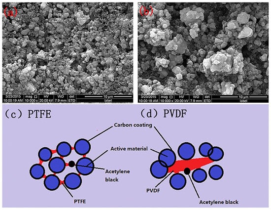 Figure 74. SEM image of LiFePO4/C electrodes prepared using (a) aqueous binders of PTFE and (b) PVDF, as well as the electrodes combined with (c) aqueous binders of PTFE and (d) PVDF [75][58].
3.2. SF Binders of PTFE
Polymer fibrillation requires materials with unique characteristics. Currently, the most optimal selection for a binder is limited to PTFE due to its exceptional mechanical qualities, high crystallinity (achieving 97% or more post-sintering) [77[59][60][61],78,79], and its ability to produce fibers. PTFE exhibits flexibility and reduced resilience compared to the properties of other polymers, with moderate tensile strength and high elongation at the break [80,81][62][63]. The material undergoes deformation under specific pressure conditions, while retaining the correct dimensions. The above behavior perfectly matches the processing requirements for the SF method of electrode stretch molding.3.2.1. Molecular Structure
PTFE possesses the highest chemical resistance, a high dielectric constant, and a wide range of operating temperatures [82][64]. The properties of PTFE result from its high crystallinity, high molecular weight, and unbranched structure. The radius of the F atom in PTFE is more significant than that of the H atom, and the C-F bonding energy is relatively vital (485 kJ mol−1) [80,81,82,83][62][63][64][65]. Therefore, the adjacent -CF2- units in the molecular chain structure cannot present a transverse cross-orientation conformation, as does polyethylene, and instead appear to be helically arranged in the overall conformation [84][66]. This spiral arrangement of the F atoms surrounds the carbon main chain. It covers the entire surface of the molecular chain, forming a protective layer of low surface energy around the C-C main chain. This non-polar and inert dense layer produces high intermolecular van der Waals repulsion.3.2.2. The Principle of Polymer Fibrillation
PTFE SF binder particles show an average particle size of 500 μm, with many oblate spheroidal particles. These particles are comprised of several folded lamellar crystals (0.54 μm long, 0.25 μm wide) [82,86][64][67]. When applying a shear load to PTFE, the oblate spheroidal particles exhibit flexibility, allowing them to elongate and form a fiber. This process is called “fibrillation” in Figure 85a,b [87][68]. Why can fibrillations occur using PTFE? There are two primary factors contributing to this phenomenon. One is the dislocation slip in the PTFE polymer crystals [28][69]. The polymer’s crystal structure determines the fibrillation behavior caused by dislocations. As shown in Figure 85c, the crystal structure of PTFE can be divided into four phases [29,88][70][71]: pseudo-hexagonal crystal (Phase I), trilobal crystal (Phase II), planar zig-zag crystal (Phase III), and hexagonal crystal (Phase IV). Taking the hexagonal crystals of Phase IV as an example, the pre-fibrillation operation in the range of 19–30 °C transforms the crystalline phase of PTFE from Phase II to Phase IV. The PTFE’s repeating distance along the molecular axis increases from 1.65 nm in the triple-diagonal crystals to 1.95 nm in the hexagonal crystals. Additionally, the repeating helical structure in the molecular chain expands -CF2- from 13 to 15, accompanied by a slight expansion in the structure of the helical repeating units [88][71]. The structure of the helical repeating unit is slightly expanded in Figure 85d [89][72]. In this phase of PTFE, the cohesion between the neighboring chains is weak and easily dislocated. In order to avoid polymer chain breakage, dislocations can generally only slide along planes parallel to the polymer chains, most commonly observed as chain slip and lateral slip. The sliding deformation of PTFE along the chain (c-axis of the hexagonal system) has been reported to be easier to deform into nanofiber structures under a high aspect ratio, as shown in Figure 85e [89][72].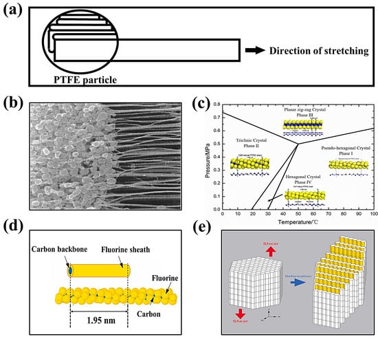 Figure 85. (a) PTFE spheres are stretched into banded fibers [87][68]. (b) SEM image (2 μm) of PTFE fibrillation [87][68]. (c) Phase diagram of PTFE [88][71]. (d) The individual PTFE polymer chain with helical structure and its simplified cylinder model [89][72]. (e) The PTFE crystals with slip dislocations occurring under shear [89][72].
3.2.3. Factors Affecting PTFE Fibrillation
Currently, there are fewer studies dedicated to discussing the influence of fibrillation properties. In the field of SF batteries research, Maxwell’s experimental data show that the impedance of the original fibrillated electrode film is related to the feed rate and the shear force [44][73]. Related reports in other fields also assist in investigating the mechanical behavior of PTFE. Aimin Zhang et al. [90][74] explored the fibrillation mechanism, crystallization behavior, and mechanical properties of in situ fiber PTFE-reinforced PP composites. The experimental results showed that the shear rate is the key parameter affecting the morphological evolution of PTFE, and the processing time also affects the morphology of PTFE, to a certain extent. The influencing factor of PTFE deformation may consist of a single variable or a synergistic effect of multiple variables. As a binder in polymer fibrillation, PTFE should possess a smaller particle size and a higher molecular weight.4. SF Process with PTFE Binder
4.1. Positive Characteristics
Figure 96a shows a comparison of the wet and dry processes, and Figure 96b shows the SEM images of the electrodes for the wet and dry processes (polymer fibrillation). Polymer fibrillation stands out in the SF approach to batteries because of the following five advantages.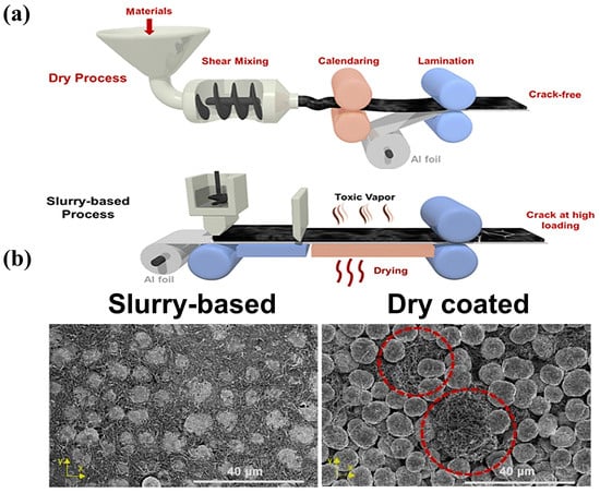 Figure 96. (a) Scheme of the PTFE-based SF and SC processes [101][75]; (b) the top surface of slurry-based LNMO electrodes and SF coated eletrodes [101][75].
- I.
-
It is environmentally friendly and suitable for large-scale production.NMP solvent is toxic, unfriendly to the environment, and needs to be recycled using the traditional wet process. The SF process does not require solvent in the electrode coating process to reduce baking and solvent recovery, the process is simpler, the equipment covers a smaller area, and the method is more suitable for the large-scale production of electrodes.
- II.
-
It exhibits a flatter electrode shape than that from the wet process.Because the wet method requires solvent, after the solvent evaporation, the active substance and conductive agent will leave more spaces between the gaps, leading to the low compaction density of the material. The SF method does not exist in the drying process, so there is no solvent evaporation left after the gap, and the contact between the particles is closer.
- III.
-
It offers greater compaction density.After compaction under dry conditions, there are fewer cracks, micropores, and other problems. The compacted density of lithium iron phosphate and SF battery energy density may be improved. According to Maxwell’s experimental data [44][73], the energy density of the SF electrode can be more than 300 Wh/kg, and has the possibility to realize 500 Wh/kg.
- IV.
-
It improves the performance of the batteryIn the wet process, after the battery has gone through many cycles, the stresses within the active particles continue to accumulate, leading to cracks in the profile, which ultimately reduces the performance of the battery. In the SF process, the fiber network is wrapped around the surface of the active material, and the mesh structure remains intact after many cycles of charging and discharging.
- V.
-
It allows for the possibility of prepare solid-state batteries.Empowered by SF technology, the manufacturing process for creating solid-state battery electrodes can be completely dried, eliminating the problem of solvent molecules remaining after drying in the wet process. In addition, the use of the original fibrillation manufacturing solid electrolyte film can reduce manufacturing costs so that solid-state batteries can also be more productive.
4.2. Development Status of SF Process with PTFE Binder
4.2.1. Effect of PTFE on SF Batteries
The properties of PTFE determine the performance of the solvent-free batteries and influence the SF process at the fundamental level. Relevant studies have been devoted to exploring whether changing the PTFE has an impact on the battery system, and the standard variables include the side reactions of positive and negative electrodes, ultra-low content (0.1–0.5 wt%), crystallinity, modified molecules of PTFE, substitutes for PTFE, and synergistic polymer binder.- I.
-
Side reactions of PTFE binders
- II.
-
Crystallinity
- III.
-
Modified materials
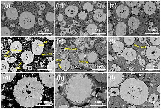 Figure 117. Cross-sectional SEM images of cathodes prepared (a) without binder, (b) with PTFE, and (c) with the ionic polymer. Cross-sectional SEM images of cycled (300 cycles) cathodes prepared (d,g) without binder, (e,h) with PTFE, and (f,i) with the ionic polymer [108][79].
4.2.2. Influence of Components Other Than Binders
- I.
-
Conductive additivesFor the variable of conductive additives, in 2023, Yang et al. [110][80] prepared a full battery, with different carbon active materials (graphite, stiff carbon, and soft carbon) as the negative electrode, and LiNi0.5Co0.2Mn0.3O2 as the positive electrode. As shown in Figure 128a, the hard and soft carbon negative electrodes exhibited better cycling stability than that of graphite due to their small volume expansion during charge storage, and this work successfully expanded the application scope of the PTFE-based SF process. Their group also investigated similar work, as shown in Figure 128b [111][81].
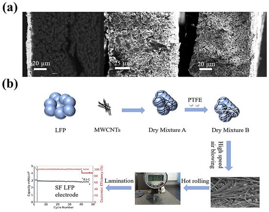 Figure 128. (a) Cross-sectional SEM images of a graphite, hard carbon, and soft carbon SF anode [108][79]. (b) SF-LFP electrode procedure [111][81].
- II.
-
Electrode materialsThe electrode material will not only have an effect on the SF electrode method alone, but it will also affect the overall capacity of the SF batteries. For SF electrode technology, measures such as developing electrode materials with higher specific capacity, increasing the proportion of active substances, and selecting active substances in the appropriate voltage range could enhance the overall performance of the SF batteries. Based on the method using the PTFE solvent-free electrode to adjust for the variation of other components, it will be expected to obtain higher performance batteries. This means that there is an excellent opportunity to prepare high-capacity batteries from the perspective of the PTFE solvent-free process.
- III.
-
CollectorsAlthough there are previous works reporting on collector-free LIBs, most of them focus on the design of an integrated battery structure concept. Currently, the SF batteries usually obtained using the polymer fibrillation method use temperatures of 180 °C and above [] to hot press and hold electrode self-supporting film for a period of time, while employing collectors such as aluminum foil, copper foil, carbon coated aluminum foil, etc.
4.2.3. Innovative Technology and System
The exploration of battery processes and systems is also essential. Nevertheless, several efforts have also focused on novel SF battery systems, such as those involving high-voltage, solid-state, and high-load battery systems.- I.
-
High-speed airflow technology
- II.
-
Lithium-sulfur (Li-S) batteries
- III.
-
High-voltage batteries
- IV.
-
High-load batteries
- V.
-
Solid-state batteries
References
- Dang, C.C.; Mu, Q.; Xie, X.B.; Sun, X.Q.; Yang, X.Y.; Zhang, Y.P.; Maganti, S.; Huang, M.N.; Jiang, Q.L.; Seok, I.; et al. Recent Progress in Cathode Catalyst for Nonaqueous Lithium Oxygen Batteries: A review. Adv. Compos. Hybrid Mater. 2022, 5, 606–626.
- Eng, A.Y.S.; Soni, C.B.; Lum, Y.; Khoo, E.; Yao, Z.; Vineeth, S.K.; Kumar, V.; Lu, J.; Johnson, C.S.; Wolverton, C.; et al. Theory-Guided Experimental Design in Battery Materials Research. Sci. Adv. 2022, 8, eabm2422.
- Jiang, M.; Danilov, D.L.; Eichel, R.A.; Notten, P.H.L. A Review of Degradation Mechanisms and Recent Achievements for Ni-Rich Cathode-Based Li-Ion Batteries. Adv. Energy Mater. 2021, 11, 2103005.
- Kalnaus, S.; Dudney, N.J.; Westover, A.S.; Herbert, E.; Hackney, S. Solid-State Batteries: The Critical Role of Mechanics. Science 2023, 381, eabg5998.
- Li, J.L.; Fleetwood, J.; Hawley, W.B.; Kays, W. From Materials to Cell: State-of-the-Art and Prospective Technologies for Lithium-Ion Battery Electrode Processing. Chem. Rev. 2022, 122, 903–956.
- Liu, W.; Placke, T.; Chau, K.T. Overview of Batteries and Battery Management for Electric Vehicles. Energy Rep. 2022, 8, 4058–4084.
- Wang, W.; Yuan, B.Q.; Sun, Q.; Wennersten, R. Application of Energy Storage in Integrated Energy Systems-A Solution to Fluctuation and Uncertainty of Renewable Energy. J. Energy Storage 2022, 52, 104812.
- Viswanathan, V.; Epstein, A.H.; Chiang, Y.M.; Takeuchi, E.; Bradley, M.; Langford, J.; Winter, M. The Challenges and Opportunities of Battery-Powered Flight. Nature 2022, 601, 519–525.
- Xing, C.W.; Li, M.C.; Liu, L.Y.; Lu, R.; Liu, N.; Wu, W.J.; Yuan, D.D. A Comprehensive Review on the Blending Condition Between Virgin and RAP Asphalt Binders in Hot Recycled Asphalt Mixtures: Mechanisms, Evaluation Methods, and Influencing Factors. J. Clean. Prod. 2023, 398, 136515.
- Zhu, C.; Usiskin, R.E.; Yu, Y.; Maier, J. The Nanoscale Circuitry of Battery Electrodes. Science 2017, 358, eaao2808.
- Ludwig, A.; Wu, M.; Kharicha, A. On The Importance of Modeling 3D Shrinkage Cavities for the Prediction of Macrosegregation in Steel Ingots. CFD Model. Simu. Mat. Pro. 2016, 2016, 1–10.
- Pillai, A.M.; Salini, P.S.; John, B.; Devassy, M.T. Aqueous Binders for Cathodes: A Lodestar for Greener Lithium Ion Cells. Energy Fuels 2022, 36, 5063–5087.
- Guo, R.N.; Han, W.Q. Effects of Structure and Properties of Polar Polymeric Binders on Lithium-ion Batteries. Inorg. Mater. 2019, 34, 1021–1029.
- Wang, Y.B.; Yang, Q.; Guo, X.; Yang, S.; Chen, A.; Liang, G.J.; Zhi, C.Y. Strategies of Binder Design for High-Performance Lithium-Ion Batteries: A Mini Review. Rare Metals 2022, 41, 745–761.
- Pettinger, K.-H.; Dong, W. When Does the Operation of a Battery Become Environmentally Positive? J. Electrochem. Soc. 2017, 164, A6274.
- Al-Shroofy, M.; Zhang, Q.; Xu, J.; Chen, T.; Kaur, A.P.; Cheng, Y.-T. Solvent-Free Dry Powder Coating Process for Low-Cost Manufacturing of LiNi1/3Mn1/3Co1/3O2 Cathodes in Lithium-Ion Batteries. J. Power Sources 2017, 352, 187–193.
- Ludwig, B.; Liu, J.; Chen, I.M.; Liu, Y.; Shou, W.; Wang, Y.; Pan, H. Understanding Interfacial-Energy-Driven Dry Powder Mixing for Solvent-Free Additive Manufacturing of Li-Ion Battery Electrodes. Ad. Mater. Interfaces 2017, 4, 1700570.
- Shiraki, S.; Oki, H.; Takagi, Y.; Suzuki, T.; Kumatani, A.; Shimizu, R.; Haruta, M.; Ohsawa, T.; Sato, Y.; Ikuhara, Y.; et al. Fabrication of All-Solid-State Battery Using Epitaxial LiCoO2 Thin Films. J. Power Sources 2014, 267, 881–887.
- Subramanyam, G.; Cole, M.W.; Sun, N.X.; Kalkur, T.S.; Sbrockey, N.M.; Tompa, G.S.; Guo, X.; Chen, C.; Alpay, S.P.; Rossetti, G.A.; et al. Challenges and Opportunities for Multi-Functional Oxide Thin Films for Voltage Tunable Radio Frequency/Microwave Components. J. Appl. Phys. 2013, 114, 191301.
- Sotomayor, M.E.; Torre-Gamarra, C.d.l.; Levenfeld, B.; Sanchez, J.-Y.; Varez, A.; Kim, G.-T.; Varzi, A.; Passerini, S. Ultra-Thick Battery Electrodes for High Gravimetric and Volumetric Energy Density Li-Ion Batteries. J. Power Sources 2019, 437, 226923.
- Trembacki, B.; Duoss, E.; Oxberry, G.; Stadermann, M.; Murthy, J. Mesoscale Electrochemical Performance Simulation of 3D Interpenetrating Lithium-Ion Battery Electrodes. J. Electrochem. Soc. 2019, 166, A923.
- Carneiro, O.S.; Silva, A.F.; Gomes, R. Fused Deposition Modeling with Polypropylene. Mater. Des. 2015, 83, 768–776.
- Kirsch, D.J.; Lacey, S.D.; Kuang, Y.; Pastel, G.; Xie, H.; Connell, J.W.; Lin, Y.; Hu, L. Scalable Dry Processing of Binder-Free Lithium-Ion Battery Electrodes Enabled by Holey Graphene. ACS Appl. Energy Mater. 2019, 2, 2990–2997.
- Han, X.; Funk, M.R.; Shen, F.; Chen, Y.-C.; Li, Y.; Campbell, C.J.; Dai, J.; Yang, X.; Kim, J.W.; Liao, Y.; et al. Scalable Holey Graphene Synthesis and Dense Electrode Fabrication toward High-Performance Ultracapacitors. ACS Nano 2014, 8, 8255–8265.
- Lee, D.J.; Jang, J.; Lee, J.-P.; Wu, J.; Chen, Y.-T.; Holoubek, J.; Yu, K.; Ham, S.-Y.; Jeon, Y.; Kim, T.-H.; et al. Physio-Electrochemically Durable Dry-Processed Solid-State Electrolyte Films for All-Solid-State Batteries. Adv. Funct. Mater. 2023, 33, 2301341.
- Wood, D.L.; Wood, M.; Li, J.; Du, Z.; Ruther, R.E.; Hays, K.A.; Muralidharan, N.; Geng, L.; Mao, C.; Belharouak, I. Perspectives on The Relationship Between Materials Chemistry and Roll-to-Roll Electrode Manufacturing for High-Energy Lithium-Ion Batteries. Energy Stor. Mater. 2020, 29, 254–265.
- Ludwig, B.; Zheng, Z.; Shou, W.; Wang, Y.; Pan, H. Solvent-Free Manufacturing of Electrodes for Lithium-ion Batteries. Sci. Rep. 2016, 6, 23150.
- Li, Y.; Wu, Y.; Wang, Z.; Xu, J.; Ma, T.; Chen, L.; Li, H.; Wu, F. Progress in Solvent-Free Dry-Film Technology for Batteries and Supercapacitors. Mater. Today 2022, 55, 92–109.
- Lu, Y.; Zhao, C.-Z.; Yuan, H.; Hu, J.-K.; Huang, J.-Q.; Zhang, Q. Dry Electrode Technology, The Rising Star in Solid-state Battery Industrialization. Matter 2022, 5, 876–898.
- Zou, F.; Manthiram, A. A Review of the Design of Advanced Binders for High-Performance Batteries. Adv. Energy Mater. 2020, 10, 2002508.
- Wu, Y.; Li, Y.; Wang, Y.; Liu, Q.; Chen, Q.; Chen, M. Advances and Prospects of PVDF Based Polymer Electrolytes. J. Energy Chem. 2022, 64, 62–84.
- Zhu, T.; Sternlicht, H.; Ha, Y.; Fang, C.; Liu, D.; Savitzky, B.H.; Zhao, X.; Lu, Y.; Fu, Y.; Ophus, C.; et al. Formation of Hierarchically Ordered Structures in Conductive Polymers to Enhance the Performances of Lithium-Ion Batteries. Nat. Energy 2023, 8, 129–137.
- Oh, J.; Choi, S.H.; Chang, B.; Lee, J.; Lee, T.; Lee, N.; Kim, H.; Kim, Y.; Im, G.; Lee, S.; et al. Elastic Binder for High-Performance Sulfide-Based All-Solid-State Batteries. ACS Energy Lett. 2022, 7, 1374–1382.
- Mu, P.; Zhang, H.; Jiang, H.; Dong, T.; Zhang, S.; Wang, C.; Li, J.; Ma, Y.; Dong, S.; Cui, G. Bioinspired Antiaging Binder Additive Addressing the Challenge of Chemical Degradation of Electrolyte at Cathode/Electrolyte Interphase. J. Am. Chem. Soc. 2021, 143, 18041–18051.
- Maleki, H.; Deng, G.; Kerzhner-Haller, I.; Anani, A.; Howard, J.N. Thermal Stability Studies of Binder Materials in Anodes for Lithium-Ion Batteries. J. Electrochem. Soc 2000, 147, 4470.
- Yonaga, A.; Kawauchi, S.; Mori, Y.; Xuanchen, L.; Ishikawa, S.; Nunoshita, K.; Inoue, G.; Matsunaga, T. Effects of Dry Powder Mixing on Electrochemical Performance of Lithium-ion Battery Electrode Using Solvent-Free Dry Forming Process. J. Power Sources 2023, 581, 233466.
- Zhang, Z.; Han, D.; Xiao, M.; Wang, S.; Feng, Y.; Huang, S.; Meng, Y. New Potential Substitute of PVDF Binder: Poly(propylene carbonate) for Solvent-Free Manufacturing High-Loading Cathodes of LiFePO4|Li Batteries. Ionics 2023, 29, 3895–3906.
- Abdel-Hakim, A.; El-Basheer, T.M.; Abdelkhalik, A. Mechanical, Acoustical and Flammability Properties of SBR and SBR-PU Foam Layered Structure. Poly. Test. 2020, 88, 106536.
- Li, Y.; Wu, Y.; Ma, T.; Wang, Z.; Gao, Q.; Xu, J.; Chen, L.; Li, H.; Wu, F. Long-Life Sulfide All-Solid-State Battery Enabled by Substrate-Modulated Dry-Process Binder. Adv. Energy Mater. 2022, 12, 2201732.
- Park, J.; Willenbacher, N.; Ahn, K.H. How the Interaction Between Styrene-Butadiene-Rubber (SBR) Binder and a Secondary Fluid Affects the Rheology, Microstructure and Adhesive Properties of Capillary-Suspension-Type Graphite Slurries Used for Li-ion Battery Anodes. Colloids Surf. A Physicochem. Eng. Asp. 2019, 579, 123692.
- Dueramae, I.; Okhawilai, M.; Kasemsiri, P.; Uyama, H.; Kita, R. Properties Enhancement of Carboxymethyl Cellulose with Thermo-Responsive Polymer as Solid Polymer Electrolyte for Zinc Ion Battery. Sci. Rep. 2020, 10, 12587.
- Kim, J.; Choi, J.; Park, K.; Kim, S.; Nam, K.W.; Char, K.; Choi, J.W. Host–Guest Interlocked Complex Binder for Silicon–Graphite Composite Electrodes in Lithium Ion Batteries. Adv. Energy Mater. 2022, 12, 2103718.
- Ibrahim, S.M.; El Salmawi, K.M. Preparation and Properties of Carboxymethyl Cellulose (CMC)/Sodium alginate (SA) Blends Induced by Gamma Irradiation. J. Polym. Environ. 2013, 21, 520–527.
- Xu, Z.; Yang, J.; Zhang, T.; Nuli, Y.; Wang, J.; Hirano, S.-i. Silicon Microparticle Anodes with Self-Healing Multiple Network Binder. Joule 2018, 2, 950–961.
- Hu, Y.; Shao, D.; Chen, Y.; Peng, J.; Dai, S.; Huang, M.; Guo, Z.-H.; Luo, X.; Yue, K. A Physically Cross-Linked Hydrogen-Bonded Polymeric Composite Binder for High-Performance Silicon Anodes. ACS Appl. Energy Mater. 2021, 4, 10886–10895.
- Senthil, C.; Kim, S.-S.; Jung, H.Y. Flame Retardant High-Power Li-S Flexible Batteries Enabled by Bio-macromolecular Binder Integrating Conformal Fractions. Nat. Commun. 2022, 13, 145.
- Mackanic, D.G.; Yan, X.; Zhang, Q.; Matsuhisa, N.; Yu, Z.; Jiang, Y.; Manika, T.; Lopez, J.; Yan, H.; Liu, K.; et al. Decoupling of Mechanical Properties and Ionic Conductivity in Supramolecular Lithium Ion Conductors. Nat. Commun. 2019, 10, 5384.
- Dong, T.; Zhang, H.; Hu, R.; Mu, P.; Liu, Z.; Du, X.; Lu, C.; Lu, G.; Liu, W.; Cui, G. A Rigid-Flexible Coupling Poly (vinylene carbonate) Based Cross-Linked Network: A versatile Polymer Platform for Solid-state Polymer Lithium Batteries. Energy Stor. Mater. 2022, 50, 525–532.
- Xia, J.; Wang, Z.; Rodrig, N.D.; Nan, B.; Zhang, J.; Zhang, W.; Lucht, B.L.; Yang, C.; Wang, C. Super-Reversible CuF2 Cathodes Enabled by Cu2+-Coordinated Alginate. Adv. Mater. 2022, 34, 2205229.
- Jeong, Y.K.; Kwon, T.-w.; Lee, I.; Kim, T.-S.; Coskun, A.; Choi, J.W. Millipede-inspired structural design principle for high performance polysaccharide binders in silicon anodes. Energy Environ. Sci. 2015, 8, 1224–1230.
- Strand, A.; Kouko, J.; Oksanen, A.; Salminen, K.; Ketola, A.; Retulainen, E.; Sundberg, A. Enhanced Strength, Stiffness and Elongation Potential of Paper by Spray Addition of Polysaccharides. Cellulose 2019, 26, 3473–3487.
- Qin, T.; Yang, H.; Li, Q.; Yu, X.; Li, H. Design of Functional Binders for High-Specific-Energy Lithium-Ion Batteries: From Molecular Structure to Electrode Properties. Ind. Eng. Chem. Res. 2023.
- Wang, X.; Liu, S.; Zhang, Y.; Wang, H.; Aboalhassan, A.A.; Li, G.; Xu, G.; Xue, C.; Yu, J.; Yan, J.; et al. Highly Elastic Block Copolymer Binders for Silicon Anodes in Lithium-Ion Batteries. ACS Appl. Mater. Interfaces 2020, 12, 38132–38139.
- Ignatieva, L.N.; Mashchenko, V.A.; Zverev, G.A.; Ustinov, A.Y.; Slobodyuk, A.B.; Bouznik, V.M. Study of The Manufactured Copolymers of Ethylene with Tetrafluoroethylene. J. Fluor. Chem. 2020, 231, 109460.
- Zhang, Y.; Lu, S.; Wang, Z.; Volkov, V.; Lou, F.; Yu, Z. Recent Technology Development in Solvent-Free Electrode Fabrication for Lithium-Ion Batteries. Renew. Sust. Energ. Rev. 2023, 183, 113515.
- Huang, S.; Huang, X.T.; Huang, Y.Y.; He, X.Q.; Zhuo, H.T.; Chen, S.J. Rational Design of Effective Binders for LiFePO4 Cathodes. Polymers 2021, 13, 3146.
- Liu, Y.; Zhang, R.; Wang, J.; Wang, Y. Current and Future Lithium-Ion Battery Manufacturing. iScience 2021, 24, 102332.
- Gao, S.; Su, Y.; Bao, L.; Li, N.; Chen, L.; Zheng, Y.; Tian, J.; Li, J.; Chen, S.; Wu, F. High-Performance LiFePO4/C Electrode with Polytetrafluoroethylene as An Aqueous-Based Binder. J. Power Sources 2015, 298, 292–298.
- Li, W.; Mays, S.; Lam, D. Material and Finite Element Analysis of Poly(tetrafluoroethylene) otary Seals. Plast. Rubber Compos. 2002, 31, 359–363.
- Brown, E.N.; Rae, P.J.; Bruce Orler, E.; Gray, G.T.; Dattelbaum, D.M. The Effect of Crystallinity on the Fracture of Polytetrafluoroethylene (PTFE). Mater. Sci. Eng. C 2006, 26, 1338–1343.
- Brown, E.N.; Dattelbaum, D.M. The Role of Crystalline Phase on Fracture and Microstructure Evolution of Polytetrafluoroethylene (PTFE). Polymer 2005, 46, 3056–3068.
- Joyce, J.A. Fracture Toughness Evaluation of Polytetrafluoroethylene. Polym. Eng. Sci. 2003, 43, 1702–1714.
- Rae, P.J.; Brown, E.N. The Properties of Poly(tetrafluoroethylene) (PTFE) in Tension. Polymer 2005, 46, 8128–8140.
- Pruitt, L.A. Deformation, Yielding, Fracture and Fatigue Behavior of Conventional and Highly Cross-Linked Ultra High Molecular Weight Polyethylene. Biomaterials 2005, 26, 905–915.
- Brown, E.N.; Trujillo, C.P.; Gray, G.T.; Rae, P.J.; Bourne, N.K. Soft Recovery of Polytetrafluoroethylene Shocked Through The Crystalline Phase II-III Transition. J. Appl. Phys. 2007, 101, 024916.
- Millett, J.C.F.; Brown, E.N.; Gray, G.T.; Bourne, N.K.; Wood, D.C.; Appleby-Thomas, G. The Effects of Changing Chemistry on the Shock Response of Basic Polymers. J. Dyn. Behav. Mater. 2016, 2, 326–336.
- Lee, D.; Manthiram, A. Stable Cycling with Intimate Contacts Enabled by Crystallinity-Controlled PTFE-Based Solvent-Free Cathodes in All-Solid-State Batteries. Small Methods 2023, 7, 2201680.
- Kitamura, T.; Okabe, S.; Tanigaki, M.; Kurumada, K.; Ohshima, M.; Kanazawa, S. Morphology Change in Polytetrafluoroethylene (PTFE) Porous Membrane Caused by Heat Treatment. Polym. Eng. Sci. 2000, 40, 809–817.
- Wecker, S.M.; Davidson, T.; Baker, D.W. Preferred Orientation of Crystallites in Uniaxially Deformed Polytetrafluoroethylene. J. Appl. Phys. 1972, 43, 4344–4348.
- Puts, G.J.; Crouse, P.; Ameduri, B.M. Polytetrafluoroethylene: Synthesis and Characterization of the Original Extreme Polymer. Chem. Rev. 2019, 119, 1763–1805.
- Wu, J.; Wang, H.; Feng, B.; Li, Y.; Wu, S.; Yin, Q.; Yu, Z.; Huang, J. The Effect of Temperature-Induced Phase Transition of PTFE on The Dynamic Mechanical Behavior and Impact-Induced Initiation Characteristics of Al/PTFE. Polym. Test. 2020, 91, 106835.
- Sato, K.; Tominaga, Y.; Imai, Y.; Yoshiyama, T.; Aburatani, Y. Deformation Capability of Poly(tetrafluoroethylene) Materials: Estimation with X-ray Diffraction Measurements. Polym. Test 2022, 113, 107690.
- Hieu, D.; Joon, S.; Yudi, Y. Dry Electrode Coating Technology; Maxwell Technologies: San Diego, CA, USA, 2018; Available online: https://api.semanticscholar.org/CorpusID:201928996 (accessed on 19 October 2023).
- Zhang, A.; Chai, J.; Yang, C.; Zhao, J.; Zhao, G.; Wang, G. Fibrosis Mechanism, Crystallization Behavior and Mechanical Properties of In-Situ Fibrillary PTFE Reinforced PP Composites. Mater. Des. 2021, 211, 110157.
- Yao, W.; Chouchane, M.; Li, W.; Bai, S.; Liu, Z.; Li, L.; Chen, A.X.; Sayahpour, B.; Shimizu, R.; Raghavendran, G.; et al. A 5 V-Class Cobalt-Free Battery Cathode with High Loading Enabled by Dry Coating. Energy Environ. Sci. 2023, 16, 1620–1630.
- Wu, Q.; Zheng, J.P.; Hendrickson, M.; Plichta, E.J. Dry Process for Fabricating Low Cost and High Performance Electrode for Energy Storage Devices. MRS Adv. 2019, 4, 857–863.
- Li, G. The Influence of Polytetrafluorethylene Reduction on the Capacity Loss of the Carbon Anode for Lithium Ion Batteries. Solid State Ion. 1996, 90, 221–225.
- Tao, R.; Tan, S.; Meyer Iii, H.M.; Sun, X.-G.; Steinhoff, B.; Sardo, K.; Bishtawi, A.; Gibbs, T.; Li, J. Insights into the Chemistry of the Cathodic Electrolyte Interphase for PTFE-Based Dry-Processed Cathodes. ACS Appl. Mater. Interfaces 2023, 15, 40488–40495.
- Hong, S.B.; Lee, Y.J.; Kim, U.H.; Bak, C.; Lee, Y.M.; Cho, W.; Hah, H.J.; Sun, Y.K.; Kim, D.W. All-Solid-State Lithium Batteries: Li+-Conducting Ionomer Binder for Dry-Processed Composite Cathodes. ACS Energy Letter. 2022, 7, 1092–1100.
- Zhang, Y.; Huld, F.; Lu, S.; Jektvik, C.; Lou, F.; Yu, Z. Revisiting Polytetrafluorethylene Binder for Solvent-Free Lithium-Ion Battery Anode Fabrication. Batteries 2022, 8, 57.
- Zhang, Y.; Lu, S.; Lou, F.; Yu, Z. Solvent-free Lithium Iron Phosphate Cathode Fabrication with Fibrillation of Polytetrafluoroethylene. Electrochim. Acta 2023, 456, 142469.
- Zhou, H.; Liu, M.; Gao, H.; Hou, D.; Yu, C.; Liu, C.; Zhang, D.; Wu, J.-C.; Yang, J.; Chen, D. Dense Integration of Solvent-Free Electrodes for Li-Ion Supercabattery with Boosted Low Temperature Performance. J. Power Sources 2020, 473, 228553.
- Fiedler, M.; Cangaz, S.; Hippauf, F.; Dörfler, S.; Abendroth, T.; Althues, H.; Kaskel, S. Mechanistic Insights into the Cycling Behavior of Sulfur Dry-Film Cathodes. Adv. Sustain. Syst. 2023, 7, 2200439.
- Tao, R.; Steinhoff, B.; Sun, X.-G.; Sardo, K.; Skelly, B.; Meyer, H.M.; Sawicki, C.; Polizos, G.; Lyu, X.; Du, Z.; et al. High-Throughput and High-performance Lithium-ion Batteries via Dry Processing. Chem. Eng. J. 2023, 471, 144300.
- Shin, D.; Nam, J.S.; Linh Nguyen, C.T.; Jo, Y.; Lee, K.; Hwang, S.M.; Kim, Y.J. Design of Densified Nickel-Rich Layered Composite Cathode via The Dry-Film Process for Sulfide-Based Solid-State Batteries. J. Mater. Chem. A 2022, 10, 23222–23231.
