Your browser does not fully support modern features. Please upgrade for a smoother experience.
Please note this is a comparison between Version 1 by Ryohei Mori and Version 2 by Lindsay Dong.
Lithium sulfur batteries (LSBs) have demonstrated to be a promising candidate battery to serve as the next-generation secondary battery, owing to its enhanced theoretical specific energy, economy, and environmental friendliness. Its inferior cyclability, however, which is primarily due to electrode deterioration caused by the lithium polysulfide shuttle effect, is still a major problem for the real industrial usage of LSBs. The optimization of the separator and functional barrier layer is an effective strategy for remedying these issues.
- lithium sulfur battery
- rechargeable battery
- separator
1. Introduction
The propagation of modern human society based on the electronic industry has demanded stronger and cheaper energy storage systems. Among these, lithium ion batteries (LIBs) have been aggressively studied and developed because of their high endurance against electrochemistry variation and their stable usage for application in various types of electronic devices, including smart phones, mobile phones, EVs, etc., even though LIBs still suffer from limited capacity, high price, and safety issues, including their flammable nature. Due to these reasons, it would be difficult for LIBs to fulfill the demand for upcoming new industrial applications, such as drones, EVs, military power supplies, and stationary electrical power stations, because they always demand higher capacity as well as safer and economically friendly rechargeable batteries [1][2][3][1,2,3]. In this regard, lithium sulfur batteries (LSBs) could be one of several alternative candidate rechargeable batteries because of their high theoretical capacity and energy density (1675 mAh g−1 and 2600 Wh Kg−1, respectively). The corresponding values for LIBs are 240–280 mAh g−1 and 350–400 Wh Kg−1, respectively. Apart from the nature of LIBs, the electrochemical reaction of LSBs is different from that of LIBs due to the presence of a sulfur cathode, and can be expressed as:
S + 2Li → Li
2
S (E
0
= 2.20 V vs. Li/Li
+
)
As a result, LSBs can offer 5–7 times higher energy density than that of LIBs. Combined with its other advantages, i.e., sulfur being naturally abundant, cheap, and a non-toxic element, LSBs can be considered as one of the candidates for next-generation rechargeable batteries [4][5][6][7][4,5,6,7]. The typical configuration of an LSB is shown in Figure 1.
Lithium metal is the anode and a carbon–sulfur composite is the cathode [8]. As an ordinary battery, the separator and an electrolyte exist between the anode and cathode.
When the LSB is discharged, sulfur is reduced to Li2S by a series of electrochemical reaction while forming various types of polysulfide intermediates. Figure 2 indicates an ordinary LSB profile during a charge–discharge electrochemical reaction [9].
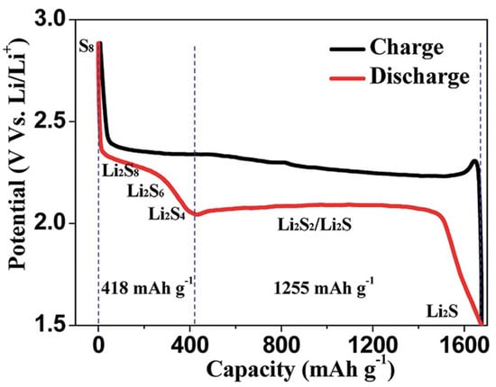
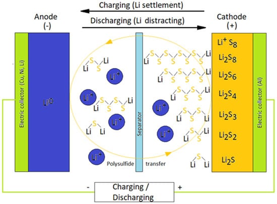
Figure 2.
During the electrochemical reaction, sulfur is reduced to Li2Sx (x = 2–8) via a stepwise electrochemical reaction to form each lithium sulfide compound. The lithium polysulfide (LiPS) compound with a relatively long chain (Li2Sx (x = 4–8)) can be highly soluble. On the other hand, the solubility of Li2Sx (x = 2–4) with short chain is lower compared to the long-chained one in the electrolyte [10]. The lithiation of sulfur occurs stepwise. At a voltage of around ~2.3 V, S8 as the solid state is reduced to soluble S82− via an initial electrochemical reaction. After that, dissolved S82− is electrochemically reduced to S42− on the cathode. During this sequential chemical process, LiPS intermediates such as S62−, S32−, and S3 are formed [11][12][11,12].
As LiPS concentration increases gradually throughout the electrochemical reaction, the viscosity of the electrolyte is enhanced. Gradual voltage decrease can be seen at this stage of reaction. After these events, one can observe a prolonged voltage of around 2.0–2.2 V, which is the major origin of LSB capacity. During this stage, an electrochemical reaction, which transforms soluble low-ordered LiPS to insoluble Li2S2 or Li2S, takes place.
At the final stage, Li2S2 would become Li2S via a reduction process. However, it should be noted that since this is the solid–solid phase reaction, the kinetics are slow due to sluggish ion diffusion. The insulating characteristics of both Li2S2 and Li2S are an additional cause for a slow electrochemical reductive reaction [13].
In spite of these advantages, LSBs still face with obstacles for practical industrial usage. For example, sulfur as a cathode active material has insulating characteristics for both the electron and the ion. LiPS as byproducts are formed in the liquid electrolyte (shuttle effect) during the discharge process, which reduce the mass and utilization of cathode sulfur. In addition, the dendrite formation of a lithium anode may cause fire once they reach the other side of the electrode through a state of battery short circuit. Furthermore, volume expansion induced by the electrochemical reaction of S to Li2S would result in loosing stability in the cathode structure [14][15][14,15].
A tremendous amount of effort has been carried out to overcome these problematic issues by increasing the cathode materials’ conductivity as well as by reducing LiPS dissolution in the electrolyte [16][17][18][19][16,17,18,19]. For example, an increase in conductivity in the cathode structure is being attempted by researchers by applying conductive carbon, carbon nanotube, graphene, as well as conductive polymer. To prevent LiPS dissolution in the electrolyte, various kinds of oxides, sulfides, nitrides, and carbides, alongside some functional materials such as quantum dot and a metal organic framework, have been replaced with carbon to reduce the shuttle effect [20][21][22][23][20,21,22,23].
Further challenges facing the cathode and electrolyte development for LSBs have been recently accelerated due to the strong influence upon the electrochemical properties. The key function of an LSB electrolyte is to transport Li+ ions in the battery efficiently, and this requires a high level of Li+ conductivity. The composition of electrolyte also largely influences the cathode electrode reaction as well as the behavior of LiPS byproducts [24][25][26][24,25,26].
In addition to designing cathodes and electrolytes, a separator is also a critical LSB component to effect its performance, especially in terms of suppressing the LiPS problem as separators can be reservoirs or capturing materials for polysulfide intermediates. Additionally, when separators have conductivity, for example, they can behave as the second current collector for electrons, which would result in enhancing the LSB electrochemical performance [27]. Nevertheless, it should be mentioned here that any additional separator weight due to modifications should be carefully regulated to maintain the battery energy density as a whole [28].
In general, polypropylene (PP) and polyethylene (PE) are utilized as separators, although it would be difficult for these nonpolar and hydrophobic materials to suppress the LiPS shuttle effect, because lithium polysulfide is more polar in nature [29]. As a preparation procedure, direct coating, slurry coating, or the filtration of functional materials onto a commercial separator would be enough to make such separators in order to prevent the LiPS shuttle effect. Besides LiPS suppression, such functional separators are also expected to possess catalytic activity and good mechanical strength for LSBs [30].
2. Separators Classified by Materials
2.1. Separator Material Facing Anode Side
2.1.1. Separator Material: Metal
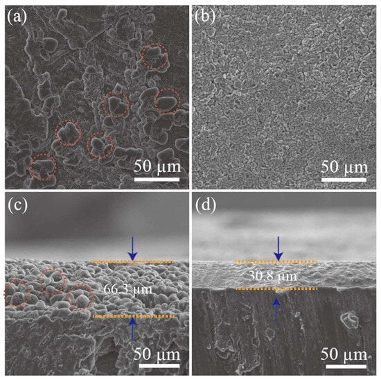
Nanoparticle- or nanolayer-based materials can inhibit dendritic Li growth by controlling lithium nucleation [31][38]. The nanoparticles in anode-facing separators behave as nucleation sites for lithium metal during electrochemical reactions as they decrease the Gibbs free energy of lithium metal electrodeposition. Initially, lithium crystal seeds would gradually grow until they cover the entire surface of the separator surface. As the process proceeds, dense lithium metal layers without dendrites are formed on the separator. Liu et al. demonstrated this phenomenon by applying lithiophilic Mg nanoparticles to an anode, whereby an LSB was prepared with this unique functional separator and which exhibited high-capacity retention (>80% after 400 cycles) [32][39]. Zuo et al. investigated the Li metal deposition phenomenon in a symmetrical cell system. As a result, lithium dendrites were seen on the surface of the pristine Li metal anode after an electrochemical discharge process, as confirmed and shown in Figure 3a. When Ag was co-deposited, Li dendrites had a tendency to fill the interspace among the Ag particles, which resulted in a lateral growth (Figure 3b). When the cross-sectional SEM image was observed, without Ag introduction, clear Li dendrites were seen after 50 cycles of the electrochemical charge–discharge process (Figure 3c). When Ag was introduced to the Li metal, in contrast, the electrode surface with a dense Ag–Li alloy layer without any Li dendrites was observed (Figure 3d).Figure 3. Surface observation: (a) bare lithium; (b) Ag co-deposited lithium with SEM. SEM observation of cross-sectional (c) bare lithium; (d) Ag co-deposited lithium [33][40].
2.1.2. Separator Material: Ceramic
Boron nitride was applied to optimize the commercial separators, owing to its intrinsic high levels of insulation and high thermal conductivity [34][43]. Boron nitride (BN)/carbon-modified composite separator was prepared with a coating method on a separator. Figure 4A shows a schematic figure and the functions of the BN/carbon separator in an LSB. During discharge, LiPS spreads out from the sulfur cathode toward the lithium anode metal. The carbon layer hinders the diffusion of the LiPS acting as the first blocking layer, and any LiPS that diffuses through the carbon layer is subsequently trapped by the BN layer acting as the second blocking layer. This BN/carbon separator was made by direct ink casting (ink composed of carbon nanopowder and BN nanopowder) onto a polypropylene separator via the slurry coating method. Owing to this simple procedure, large-scale separator fabrication (dimensions 150 mm long and 60 mm wide) could be achieved (Figure 4B). The prepared separator had sufficient mechanical strength and was able to resist physical twisting due to the strong level of adhesion between the separator, carbon, and BN nanopowders, having been bonded using a polyvinylidene fluoride (PVDF) binder (Figure 4C). Figure 4D shows the surface of a pristine commercial polypropylene separator, on which some distributed pores can be observed. After coating the separator with BN (particle size ~ 100 nm; Figure 4E) and carbon (particle size ~ 50 nm; Figure 4F) nanopowders, the pores were fully covered. BN and the carbon layer thickness were approximately 7 and 6 μm, respectively (Figure 4G). Some of the electrochemical properties of the prepared LSBs were measured. After the surface modification, lithium dendrite formation was suppressed by forming on the Li surface by an ideal Li plating/striping process (Figure 4H). Fortunately, LiPS diffusion was mitigated by an additional BN layer on the separator, thus resulting in obtaining a higher LSB electrochemical performance (Figure 4I) [34][43].
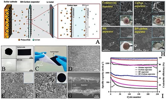
Figure 4. (A) Speculated image of the BN-carbon separator role. (B) Separator of BN coating layer. (C) Bent BN-coated separator image. Top view of SEM image of (D) intact separator. (E) BN side separator. (F) Carbon side of a BN-carbon separator. (G) Cross-sectional SEM view of a BN–carbon separator. (H) Photographs of a lithium metal anode of LSB prepared with described type of separators in each picture, after 250 cycles. (I) Cycle performances of various kinds of separators at 0.5 C [34][43].
In addition to controlling the lithium metal growth and nucleation, the oxide functional interlayer could also be ideal in suppressing the LiPS effect. Silica (SiO2) is one such material effective for preventing the LiPS shuttle effect and improving LSB performance. One of its advantages is its abundance. The thermal stability of SiO2 is also a good feature in order to confer the separator with high thermal stability [35][44]. However, its direct contact with the cathode should be prevented as SiO2 is known to react with lithium metal [36][45]. However, it should be noted that one of the SiO2-coated separator example will be presented in a later section.
2.1.3. Separator Material: Solid Electrolyte
Li6.4La3Zr1.4Ta0.6O12 (LLZTO) is the lithium ion conductive solid electrolyte, and it was coated on the PP separator on the anode side. Smooth lithium deposition was achieved due to a uniformly dispersed transportation path for the lithium ion in three-dimensional structure in LLZTO. It was also clarified that lithium ion deposition was further enhanced by adding a higher content of LLZTO by localizing a higher content of anions. Owing to these improvements, the prepared LSB presented an improved electrochemical performance with better safety due to solid electrolyte stability [37][51].
2.1.4. Other Functional Separator Materials
A modified anode-facing separator could act as a simple barrier to push back LiPS immigration from the cathode to the anode, and this would also be expected to impede Li dendrite formation. For example, there is a kind of conducting polymer that is known to capture LiPS, promoting Li ion flux and electron transportation. Li et al. prepared a conductive polypyrrole (PPy) film for a commercial anode-facing separator and succeeded in improving LSB electrochemical properties [38][52]. They deposited the PPy film on the separator by applying an Fe-based precursor and pyrrole monomer and succeeded in obtaining a PPy-modified separator (Figure 5a,b). A scanning electron microscope (SEM) observation of the pristine commercial separator exposed 100–200 nm sized nanopores (Figure 5c). In contrast, slightly smaller nanopores with sizes of 30–50 nm were observed on the PPy-coated separator (Figure 5d). The thickness and weight of the coated PPy layer were as small as 15–25 nm and ~0.13 mg cm−2, respectively, which is advantageous for industrial use in terms of energy density per weight (Figure 5e). X-ray photoelectron spectroscopy (XPS) was carried out upon both separators. It has observed a peak at 399.8 eV, which can be ascribed to N 1s with the PPy-coated separator (Figure 5f).
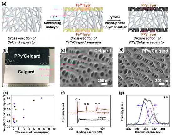
Figure 5. (a) The speculated image of PPy layer on a commercial separator by a vapor–phase polymerization method. (b) Actual image of commercial separator with and without PPy treatment. SEM image of commercial separator (c) without and (d) with PPy treatment. (e) Comparison and other examples of the weight and thickness with various types of coating. (f) XPS spectra of a separator with and without PPy treatment. The spectrum of N is originated from the PPy-treated layer. (g) Expanded N 1s spectrum of the separator with PPy treatment [38][52].
Preparing a physical barrier by introducing some kinds of lithium compound to a separator is an alternative way to reduce the unfavorable reactions between LiPS and lithium metal. This concept is different from using a material that would not react with any LSB component. Based on this concept, the lithium compound, LiF, was applied to a separator. Lewis acid lithium atoms in LiF could relate with 1,2-dimethoxyethane (DME) as Lewis alkali to form LiF–DME clusters. These clusters are viscous sol and form dense layers that would behave as a shield to prevent the shuttle effect of LiPS.
Cathode-facing functional separators could also be effective as anode-facing counterparts because they can serve as the first barrier to LiPS, potentially increasing the chances of sulfur utilization as an active material. To date, polymers, metal compounds, ceramics, carbonaceous material, and their composites have been used to alter commercial separators in order to endow them with additional positive properties [39][58]. Separators should be mechanically strong, chemically and electrochemically stable, and lightweight in order to avoid negatively impacting the density of energy of the final LSB product. Furthermore, they should possess an enhanced ionic conductivity and the ability to suppress the shuttle effect of LiPS. The functions of a cathode-facing separator can be generally classified as physical adsorption, chemical adsorption, catalytic conversion, and dual-mechanism functions, as shown in Figure 6 [40][35].
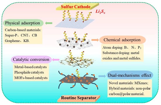
Classification and functional mechanism of functional separators in LSBs [35].
2.2. Separator Material Facing Cathode Side
2.2.1. Separator Material: Carbonaceous Materials
Commercial separators are composed primarily of PP and PE and are considered to be purely physical barriers. In light of this, a great number of research were carried out to study the influence of applying carbonaceous material to the cathode side of the separator, owing to its high electrical conductivity. These carbonaceous materials, including conductive carbon black, carbon nanotube, and graphene, are being studied with an aim to enhance LiPS suppression, cycle stability, and capacity of LSBs [41][42][59,60]. The improved electrochemical characteristics of LSBs are mainly the result of high electrical conductivity, which can confer them to behave as additional current collectors to lower the battery resistance [43][61].
For example, eight separators coated with the conducted carbon of various nano-porosities were investigated by Huang et al. to see how the material characteristics contributed to LSB separator performance [44][62]. The LSB with the nonporous carbon-loaded separator demonstrated a 1112 mAh g−1 capacity at a C/10 cycling rate, and even after 200 cycles, a stable reversible capacity of 710 mAh g−1 was maintained [45][63].
Besides conductive carbon and carbon nanotubes, graphene can be also considered as an attractive functional coated material to improve the separator properties. In general, graphene possesses high electrical conductivity, is super lightweight, has high chemical stability and ductility, and is mechanically strong. The separator coated with graphene blocks pores in the polyolefin separator, which can prevent LiPS dissipation. Reduced graphene oxide (rGO) was obtained using Hammer’s method, and it was dispersed in DMF (dimethylformamide) and combined with sodium ligno-sulfonate (SL) and hexamethylene diisocyanate (HDI). SL is rich in hydroxyl, carboxyl, and dendritic groups and it is considered an industrially cheap and available material. IR spectra elucidated a broad peak at 3400 cm−1, which can be ascribed to stretching vibrations of the hydroxyl group, and 1634 cm−1, 1402 cm−1, and 1112 cm−1 peaks were originated from carbonyl C=C, –OH, and C–O bonds in GO and SL, respectively [46][47][48][64,65,66]. The -OH bond peak disappeared at the GO/SL composite material after reacting with HDI and SL; this is due to GO reduction to rGO (Figure 78B). Zeta-potential for the rGO/SL composite was 75.14 mV. This indicates that the significantly strong electrostatic repulsion force is formed against polysulfide ions, which is negatively charged, in order to suppress the LSB shuttling effect [49][50][67,68].
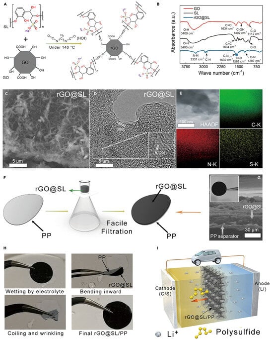
Figure 78. Synthesis procedure, microscopic observation and preparation of the rGO/SL composite and rGO/SL/PP separator [51][69]. (A) Preparation steps to make rGO/SL. (B) FTIR spectra of GO, SL, and rGO/SL. (C) Scanning electron microscopy images of the rGO/SL composite. (D) HRTEM observation of the rGO/SL composite. (E) Elemental analysis of C, N, and S for rGO/SL. (F) Preparation for the rGO/SL/PP separator. (G) Scanning electron microscopy picture of the rGO/SL/PP separator. (H) rGO/SL/PP separator image against mechanical stresses. (I) Speculated image of the rGO/SL/PP separators for suppressing LiPS shuttle effect.
This type of prepared rGO/SL composite solution was applied to a commercial PP separator using a facile vacuum filtration process. Sulfonic groups in the lignin can confer a separator with enough negative charge and reduce negatively charged LiPS diffusion. Applying this reduced graphene oxide/sodium ligno-sulfonate/separator achieved a capacity retention of 74% over 1000 cycles [51][69].
In addition to simply physically blocking LiPS, chemical bonding between polar substances is an alternative procedure to suppress LiPS diffusion. To capture polar polysulfide, polar materials are superior to hydrophobic carbon materials. Carbonaceous materials doped with various kinds of elements (e.g., N, B, S, P, F, O, Cl, Co, Ni, Fe) tend to possess polarity and have greater ability to capture LiPS [52][70]. The composite material composed of a nitrogen-doped reduced form of graphene oxide with CoS2 and NiS2 was made via a hydrothermal method [53][71]. Figure 89a shows the adsorption–desorption isotherms and pore size distribution of the cobalt nickel sulfur/nitrogen-doped reduced graphene oxide (CNS/N-rGO) composite and the one combined with sulfur, respectively. BET-specific surface area of CNS/N-rGO was 177 m2/g, and the pore volume was 0.416 cm3/g. The desorption isotherm of Barrett–Joyner–Halenda (BJH) is presented in Figure 89b. An obvious strong peak at 4 nm is proof of the porous structure of the sample, which can promote lithium ion transportation and help adsorb the LiPS, thus improving the LSB electrochemical performance [54][55][72,73]. However, after combining with sulfur, the pore volume and surface area significantly reduced, suggesting that the CNS/N-rGO was deeply immersed with sulfur. Figure 89c is the XRD pattern of the CNS/N-rGO composite material. A 26° broad peak can be ascribed to the (002) facet of the graphite. One can deduce that 53.04°, 49.03°, and 32.01° peaks corresponded to the (200), (220), and (311) CoS2 facets, respectively [56][74].
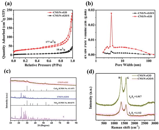
Figure 89. (a) The adsorption–desorption isotherms of N2. (b) BJH pore size distribution curves of the CNS/N-rGO composite and CNS/N-rGO/S. (c) XRD pattern of the CNS/N-rGO composite. (d) Raman spectrum of the CNS/N-rGO composite [54][72].
2.2.2. Separator Material: Metal Oxide
Metal oxides were investigated for application as LSB separators as they can generate different bonds for LiPS. Metals lose their electrons in certain conditions and become metal ions, which can generate chemical bonds to capture LiPS to prevent the shuttle effect. In addition, the metal oxides in nanostructure states would be easier to combine with polymers to become functional separators. It has been shown that LiPS diffusion can be suppressed with the Al2O3-coated layer on the separator’s cathode side as a physical block layer for LiPS. The first discharge capacity of the LSB prepared with an Al2O3-applied separator was 967 mAh g−1 at 0.2 C and deteriorated to 593.4 mAh g−1 after 50 cycles. The electrode resistance was reduced because of the porous structure of the Al2O3-coated layer that worked as an ion-conducting scaffold for capturing sulfur containing active materials [57][78].
A SiO2 nanoparticle-modified PP separator was made by Li et al. by dipping a PP separator into a sol–gel TEOS solution and Tween-80 [57][78]. This kind of separator has high wettability and thermal stability, and the resulting LSB showed considerable improvement in its electrochemical performance. The capacity decay of the LSB prepared with this SiO2–PP separator was 64% after 200 cycles at 0.2 C, which was superior than the one made with a commercial separator (45%). In addition, the capacity of LSB with SiO2–PP separator achieved 956.3, 691.5, 621, and 567.6 mAh g−1 at a 0.2, 0.5, 1, and 2 C current density, respectively [58][81].
2.2.3. Separator Material: Metal Sulfide
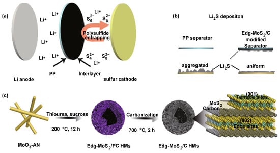
Some metal sulfides are known to adsorb LiPS, owing to their polar nature, and thus have been studied for use as a separator material. Tan et al. prepared a reduced graphene oxide/MoS2 (rGO/MoS2) layer on the cathode side of the commercial separator. The rGO behaves as a barrier for LiPS diffusion and an extra current collector, while MoS2 can capture LiPS. The prepared LSB demonstrated 1122 mAh g−1 at 0.2 C, with a low capacity fading rate of 0.116% for 500 cycles at 1 C, and an excellent performance rate of 615 mAh g−1 at 2 C [59][86]. Another study demonstrated the potential use of edge-rich MoS2/C hollow microspheres as LSB separators. The MoS2/C hollow microspheres were prepared via hydrothermal synthesis with MoO3, aniline, thiourea, and sucrose, following a carbonization process [60][87]. Carbonization was carried out in order to improve the graphitization degree of the carbon in MoS2/C hollow microspheres (Figure 910). The prepared MoS2/C hollow microspheres carry a high chemical absorption property and a high density of LiPS-capturing sites, resulting in showing excellent LiPS diffusion prevention. In addition, the phase conversion reversibility of the active sulfur species could be regulated in a stable matter with this MoS2/C composite material particularly at high C-rates and sulfur loading. Thus, the LSB arranged with the MoS2/C separator exhibited a capacity of 935 mAh g−1 at an initial cycle atof 1.0 C and it was 494 mAh g−1 even after 1000 cycles [61][88].Figure 910. Schematic model of the operation and preparation of the Edge-MoS2/C/PP separators [60][87]. (a) Image illustration of polysulfides’ capture in LSB with Edge-MoS2/C/PP separator. (b) Image illustration of Li2S deposition on the separator with edge-MoS2/C/PP and PP. (c) Synthesis procedure of the Edge-MoS2/C hollow microspheres and illustration of the Edg-MoS2/C hollow microspheres.
2.2.4. Separator Material: Metal Carbide
Titanium carbide (TiC) is regarded as a representative non-oxide ceramic material with high electrical and thermal conductivity, robust hardness, and high chemical stability [62][92]. In a recent study, TiC is acknowledged to be utilized for energy storage purposes owing to these excellent properties. Especially for LSBs, TiCs are considered to improve the cycle stability via its high polarity to capture sulfur species and its ability to reduce the LiPS shuttle effect [63][93]. In addition, the high electrical conductivity of TiC is an additional good reason for it to be an ideal sulfur scaffold material.
Liu et al. synthesized TiC nanoparticles from waste polytetrafluoroethylene as a carbon source at 500 °C, that is lower than general TiC synthesis temperature. They used this TiC as a coating material for an LSB separator and successfully mitigated the shuttling problem. The visual influence was investigated by dispersing prepared TiC nanoparticles in an LiPS solution. At the TiC–Li2S6 bottle, the yellowish color became more transparent after two hours of adsorption, whereas the bottle without TiC remained unchanged, as presented in Figure 110A,B. These results clearly imply that waste polytetrafluoroethylene-derived TiC nanoparticles have high potential in reducing LiPS shuttle effect in LSBs [64][94]. The bending exam proved TiC’s strong adhesion to the separator as shown in Figure 101C.
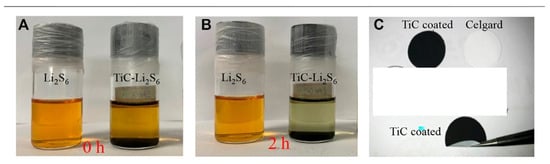
Figure 101. The pictures of LiPS capturing: (A) Before and (B) after 2 h. (C) Digital image of the TiC-coated separator and bent testing image [64][94].
2.2.5. Separator Material: Nitride
Transition metal nitrides have been applied as a catalyst and as electroanalysis devices because of their high conductivity, reactivity, and stability [65][100]. For example, in contrast to their oxide (1.0 × 10⁻³ Sm−1) and sulfide (9.7 × 10⁻²–103 Sm−1) counterparts, molybdenum nitrides possess high electrical conductivity [66][101]. Chen et al. applied molybdenum nitride on a commercial separator and the capacity of the assembled LSB was 566 mAh g−1 after 500 cycles at 0.5 C [67][102].
Kim et al. prepared a boron nitride nanotube (BNNT)-based separator for the cathode side. Lithium stripping/plating analysis was conducted to elucidate the lithium metal’s stability by observing the overpotential. When stripping/plating of lithium was conducted at 0.35 mA/cm2, a similar overpotential profile was observed for LSBs composed of all separator types; however, when it was carried out at 1 mA/cm2, the overpotentials of the commercial and BNNT separator were much more obvious than those of the p-BNNT (Figure 112a,b). This occurred because of dendrite formation and detachment caused by non-uniform lithium stripping/plating. In contrast, the higher ionic conductivity of the p-BNNT separator demonstrated the good stability of the lithium anode (Figure 112c–e).
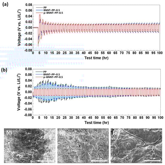
Figure 112. Lithium stripping/plating reaction with PP, BNNT, and p-BNNT-applied separator at (a) 0.35 mA/cm2 and (b) 1 mA/cm2. Top view of SEM observation of lithium metal after lithium stripping/plating reaction with (c) PPY (d) BNNT-PP-0.5, and (e) p-BNNT-PP-0.5 [68][103].
2.2.6. Separator Material: Phosphide
Transition metal phosphides generally have good electrical performance, adequate chemical adsorption ability, and significantly high catalytic capability for LiPS, which makes them an interesting choice as a separator modifier for LSBs [69][106].
Chen et al. applied CoP nanospheres as a separator coating material for LSBs [66][101]. It was found that the conductive CoP could efficiently anchor LiPS because of its polar nature and partial surface oxidation state (as confirmed via the XPS analysis), which induce Co sites to chemically capture LiPS with Co–S bonding. Owing to these characteristics, this LSB exhibited high electrochemical characteristics and excellent rate performance (725 mAh g−1 at 5 C) [70][107].
Another transitional metal phosphide was also studied by Zhao et al., who prepared FeP/spongy carbon composites with multiple adsorptions and catalytic sites as a modified material for an LSB separator [71][109]. The spongy carbon was shown to possess suitable structural stability and long ion/electron transmission channels. The addition of the FeP-endowed spongy carbon reacted with the LiPS to block shuttling and catalyze the conversion of sulfur. It was found that the FeP/spongy carbon-modified separator could reduce the flammability of the completed LSB. Benefiting from these features, the prepared LSB exhibited high cycling stability and the LSB could retain a 618 mAh g−1 capacity even after 150 cycles [71][109].
Figure 123 indicates cyclic voltammetry curves of an LSB prepared with four types of separators. Two cathodic peaks can be ascribed to the sulfur transition of soluble polysulfides to solid-state Li2S2/Li2S, and they are stronger for the LSB prepared with Ni/Ni2P–MCN. Thus, it can be suggested that Ni/Ni2P–MCN can enhance the efficiency of polysulfide conversion kinetics [72][110]. One can also observe the anodic peak approximately at 2.4 V. The one with Ni/Ni2P–MCN/PP indicated an anodic peak with a lower potential than the remaining three types, proving an enhanced Li2S2/Li2S oxidation reaction [73][74][111,112].
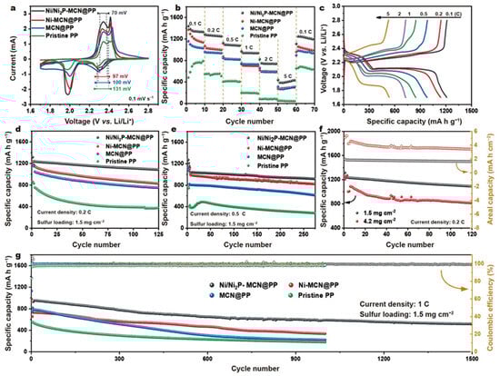
Figure 123. (a) Cyclic voltammetry. (b) Rate performances of LSB prepared with Ni/Ni2P-MCN/PP, Ni-MCN/PP, MCN/PP, and commercial PP. (c) Charge–discharge profiles of LSB prepared with Ni/Ni2P-MCN/PP at various current densities from 0.1 to 5 C. (d,e) LSB cyclic performance prepared with Ni/Ni2P-MCN/PP, MCN/PP, and pristine PP at 0.2 and 0.5 C. (f) LSB cycling performance prepared with Ni/Ni2P-MCN/PP at 0.2 C. (g) LSB cycling performance prepared with Ni/Ni2P-MCN/PP, MCN/PP, and commercial PP at 1 C [72][110].
2.2.7. Separator Material: Metal Organic Framework-Based Materials
Metal organic frameworks (MOFs) are the class of porous materials composed of metal ions and organic ligands. One of MOF application can be molecular sieves and selective gas separation on a molecular scale [75][76][77][78][79][113,114,115,116,117]. MOF and MOF-based composite materials have been investigated as porous host materials for LSB cathodes to retain sulfur due to their large specific surface area and catalytic effect for LiPS. A porous material with optimally regulated pore sizes can work as a sieve to separate desirable ions from an ionic solution such as LiPS, thus resulting in reducing their shuttle effect. In this regard, MOF and MOF-based materials are good candidate materials for LSB separators owing to their tunable pore size and specific surface area.
One example is in applying MOF–graphene oxide composite as a separator material. The preparation procedure is exhibited in Figure 134a. The MOF layer was grown initially. A desirable amount of graphene oxide (GO) solution, which was obtained by filtration, was applied onto uniformly dispersed crystalline MOF particles. It was confirmed that the MOF and GO layers were strongly adhered onto the membrane. This procedure was repeated several times to assure the quality of the preparation process. The MOF nanoparticles filled the void space tightly near the grain boundaries. A self-standing separator can be obtained by peeling off this type of material from the filter. It was found that the structural scaffold of the MOF remained intact even after over 200 electrochemical cycles. (Figure 134c). The morphological observation of the MOF/GO separator is presented in the SEM image (Figure 134d,e).
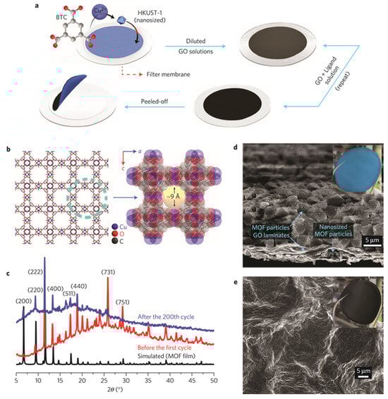
Figure 134. Preparation and material characteristics of MOF/GO separators [80][118]. (a) Illustration of preparation method to make MOF/GO separators. (b) Schematic image of HKUST-1. (c) PXRD patterns of MOF/GO separators. MOF structure remains unbroken after the discharge/charge process. (d) SEM photographs of the MOF/GO separator. The inset presents a digital image from the MOF side aspect. (e) SEM photograph of GO layer. The inset is an image from the GO side aspect.
2.2.8. Separator Material: Quantum Dot
Quantum dots (QDs) are generally super small crystalline particles with a size range of 1.0–10 nm. Recently, QDs have gained much attention for being interesting materials for electrochemical energy storage due to their large specific surface area, tunable size, short ion/electron transportation path, adjustable photoluminescence, and feasible surface functionalization [81][82][122,123]. In addition, it was reported that QDs can modify separators to suppress the shuttle effect, owing to their effective interaction with LiPS [83][124].
Atomic-layer deposition method was applied to prepare a TiO2 quantum dot-modified multiwalled carbon nanotube as the deposition material for LSB separators and succeeded in preventing the LiPS shuttling effect and improving the coulomb efficiency and cycle stability (Figure 145a) [84][121]. It was suggested that these positive effects were achieved due to an interaction between TiO2 quantum dots and LiPS that could adsorb soluble polysulfide compounds, leading to suppressing the shuttle effect. The interlayer also had abundant spacing and excellent conductivity because of the multiwalled carbon nanotube. The assembled LSB showed 1083 mAh g−1 as the initial capacity and kept a cycle capacity of 610 mAh g−1 after 600 cycles at a rate of 838 mAh g−1. Capacity decay rate was only 0.072% per cycle (Figure 145b) [85][125].
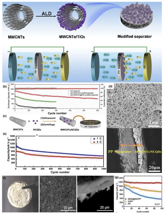
Figure 145. (a) Speculated image of the synthesis procedure of MWCNTs/TiO2 quantum dots and LSB with conventional PP and applied MWCNTs/TiO2 quantum dots. (b) Cycle tests of LSB prepared with PP, MWCNTs/PP, and MWCNTs/TiO2 quantum dots/PP. (c) Speculated image of MWCNTs/NCQDs composite and HRTEM picture of NCQDs anchored on MWCNTs surface. (d) SEM image of MWCNTs/NCQDs -applied separator and cross-sectional view of MWCNTs/NCQDs-applied separator. (e) Cycle test of the LSB assembled with MWCNTs/NCQDs-applied separator. (f) Digital and SEM image of lithium metal after plating/stripping experiments carried out with MQD/NG/PP separators for 200 cycles. (g) Cycle performance of LSB prepared with PP, G/PP, and MQD/NG/PP [85][86][87][88][125,126,127,128].
A superlight PP-coated film with multiwalled carbon nanotubes/nitrogen-doped carbon quantum dots (MWCNTs/NCQDs) was synthesized by Pang et al. (Figure 145c) [86][126]. The weight of the MWCNT/NCQD coating per area was as low as 0.15 mg cm−2 (Figure 145d).
It was found to have superior capacity retention and self-discharge suppression compared to the LSB made by Chung et al. with an MWCNT-modified separator [87][127]. The synergistic influence of the MWCNTs and NCQDs was ultimately positive, resulting in 1331 mAh g−1 as an initial capacity and presenting a stable cycling performance. The capacity decay was as low as 0.05% per cycle at 0.5 C, over 1000 cycles (Figure 145e).
Yu et al. developed a Mo2C quantum dot (MQD)-anchored nitrogen-doped graphene-deposited separator (MQD/NG) [88][128]. Figure 145f shows the optical and TEM pictures of the separator with MQD/NG/PP surface after 200 cycles. Polar Mo2C QDs offer a uniform lithium deposition and good chemical adsorption of LiPS. The LSB operated more than 1600 h with dendrite-free lithium deposition at a current density of 10 mA cm−2. The capacity of 1230 mAh g−1 was observed under stable cycle performance after 100 cycles at 0.2 C without obvious capacity decay (Figure 145g).
2.2.9. Separator Material: Mxenes
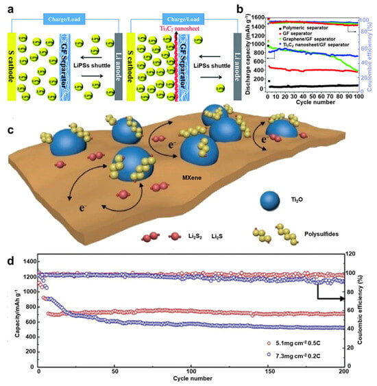
“MXenes” are materials known as two-dimensional transition metal carbides, nitrides, and carbonitrides and have been gaining significant attention owing to their high conductivity, rich functionality on Mxene surface, and exclusive two-dimensional morphologies, especially for energy storage devices [89][90][132,133]. Glass fiber and Ti3C2 composite separator were prepared by Lin et al. via a vacuum filtration process [91][143]. As displayed in Figure 156a, a few layers of a conductive Ti3C2 nanosheet with an average thickness of 1–4 nm were deposited on a glass fiber separator. This type of separator can offer strong LiPS adsorbing sites due to their high porosity, and LiPSs shuttle effect was successfully reduced when compared to a glass fiber separator without Mxene.Figure 156. (a) Speculated image of the cell with a GF or GF/Ti3C2 separator. (b) Cycling performance and coulombic efficiency at 0.5 A g–1. (c) Speculated image of the LiPS capture and process on TiO2–Ti3C2Tx structures. (d) Cycling performance of LSBs with a Ti3C2Tx–GN with different amounts of sulfur loadings [91][92][143,144].
TiO2–MXene heterostructures were prepared by Jiao et al. via the partial oxidation of Ti3C2Tx nanosheets [92][144]. It was shown that this crafted structure had a large surface area, strong ability to catch LiPS, and high conductivity and electrocatalytic activity. Figure 156c depicts how TiO2 uniformly distributed over MXene sheets can offer numbers of effective adsorbing sites to catch LiPS, while its heterostructure interface assures the rapid diffusion of LiPS to MXene, leading to its high catalytic activity for rapid LiPS conversion. The discharge capacity of LSB assembled with this TiO2–MXene-deposited separator was 662 mAh g−1 after 200 cycles at 0.5 C, which indicates 93% of capacity retention, proving its high sulfur utilization efficiency (Figure 156d).
3. Necessary Properties for LSB Separators
In general, electronic resistance and ion conductivity need to be high for LSB separators. Ionic conductivity is related to separator structure, including porosity and tortuosity. Porosity is necessary to save enough electrolytes in order to keep ionic transference in an enhanced level. Tortuosity is an additional important factor. Tortuosity is the amount to explain the morphology. As tortuosity becomes smaller, conductivity will be higher. Furthermore, wettability is also a key factor to determine ionic conductivity. Obviously, a higher electrolyte permeation could serve as an easier way for lithium ion transportation. It should also be noted that the pore size and tortuosity should be uniform in order to obtain stable current density [93][154].