1. Factors Influencing Residual Stresses
Understanding the variables that determine residual stresses is crucial to prolonging the service life of components since residual stresses can shorten their lifespan
[1][40]. Essentially, the causes of residual stresses can probably be divided into three categories; the first is non-uniform plastic deformation, the second is temperature variation, and the third is non-uniform phase change
[2][41]. The strengthening effect of the CE process depends on reasonable process parameters, mainly including the degree of expansion, mandrel speed, initial hole diameter, thickness, edge distance ratio, reaming degree, etc.
1.1. Expansion Degree
The expansion degree is one of the most critical process parameters in the CE process, and directly affects the amount of fatigue gain achieved by this process. If the degree of expansion is too small, the tightening of the hole around the formation of a certain depth of residual compressive stress layer will not strengthen the effect; The degree of expansion is too large and will cause many problems, such as SCE being used to cause an increase in the flow of metal in the direction of the axis of the hole, so that the expansion exit surface has a significant bump. The expansion between the hole diameter and the mandrel maximum diameter is referred to as the expansion degree:
where D is major mandrel diameter, t0 is sleeve thickness and 𝐷0 is beginning hole size.
Liu et al.
[3][42] determined the residual stresses by finding that mandrels of different radii produce different expansion degrees for the aluminum alloy LY12-CZ. Geometric non-linearities were taken into account to determine residual stresses for mandrels without frictional contact with the hole surface. The simulation findings demonstrate that when the quantity of extrusion increases, the maximum values of tensile and compressive stresses in the radial and circumferential residual stresses steadily rise. According to the residual stress distribution curve for 2024-T3 aluminum alloy that Kumar et al.
[4][38] obtained using finite element analysis, the tangential residual stress at the hole edge that corresponds to the 5% expanded hole was 14% higher than that of the 3% expanded hole and was 6.36% higher than that of the 4% expanded hole. Even though the expansion degree can be adjusted to greater levels, there is a certain threshold of expansion beyond which advantageous results are not evident due to strong frictional forces and surface upsetting problems connected to mandrel tugging
[5][43]. According to Ghfiri et al.
[6][44], drilling a hole while expanding can postpone the initiation and propagation of new cracks, and fatigue life is enhanced by increasing SCE. However, despite the high value of CE degrees, the projected benefits of CE were not realized in the experimental study for the two aluminum alloys, 6005A-T6 and 6082-T6
[7][18]. The local zone surrounding the hole may have been harmed during the CE process at these high values, which is one potential explanation.
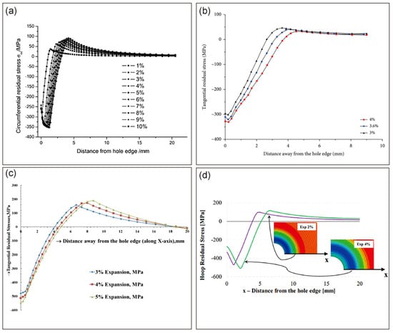
Figure 13 shows the variation in residual stress for different alloys at different expansion degrees. The applied expansion for fastener hole diameters in aluminum typically varies from 3 to 6 percent. The applied expansion range for titanium is 4.5 to 6.7 percent. There will be numerous deep microcracks in the boss after expansion if the expansion degree is too high, which will result in a reduction in fatigue strength; there will be few deep microcracks in the boss after expansion if the expansion degree is too low, which will have the opposite effect
[5][43].
Figure 13.
Variation in residual stresses along the distance away from the hole edge (
a) LY12–CZ Al alloy [3]; ( ) LY12–CZ Al alloy [42]; ( c) 2024–T3 Al alloy [4]; ( ) 2024–T3 Al alloy [38]; (
1.2. Mandrel Speed
When the fastener hole expands, the expansion bar is required to uniformly and continuously squeeze through the hole wall, so that the hole wall is completely deformed; pauses and intermittent and impact stroke phenomena should not be allowed in the expansion process. Otherwise, it will be easy to cause open seam-sleeve expansion in the sleeve fold, resulting in jamming and the broken rod phenomenon. Farhangdoost et al.
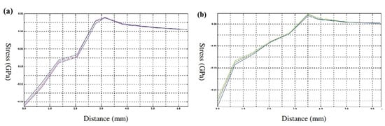
[10][11][48,49] analyzed the impact of various mandrel speeds on the distribution of residual stress around the fastener hole. As depicted in
Figure 24, the fatigue life of the fastener hole increases with increasing mandrel speed and residual stress around the hole.
Figure 24.
(
a
) Tangential residual stress distribution around the CE hole in the X–direction (
b) Tangential residual stress distribution around the CE hole in the Y–direction [10]. ) Tangential residual stress distribution around the CE hole in the Y–direction [48].
1.3. Edge Distance Ratio
Typically, a ratio of e/D is used to determine the edge distance ratio (EDR). D is the hole diameter, and e is the distance between the hole center and the plate’s undamaged edge. Due to residual stresses produced by CE and the interaction of the fastener with the unstressed edges of the plate when the edge distance is minimal, the tangential residual stress distribution around the fastener hole is no longer symmetrical to the hole center. Liu et al.
[12][50] found that when the EDR of TC4 titanium alloy specimens was reduced, the residual tangential compressive stresses in the CE hole decreased and the fatigue life was reduced.
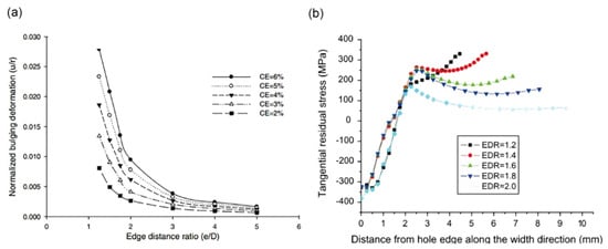
Figure 35 shows the distribution of residual stresses for different EDRs at different expansion degrees and different hole margins. As the edge distance decreases relative to the EDR, the residual tangential compressive stress at the hole edge decreases. CE slows the fracture propagation as intended at all edge ratios. This delay is brought on by a decrease in the stress intensity factor of the fractures produced by the cold expansion holes. As a result, Fatigue Technology Inc (FTI) recommends 1.75 as the minimal e/D limit
[13][51]. The residual stress field has no impact if e/D is higher than 3
[14][52].
Figure 35. (
a) Comparison of normalized bulging deformation
[14][52]; (
b) residual tangential stress distribution along the width direction on the entrance face
[12][50].
1.4. Thickness
The plate is expanded layer by layer from the inlet side to the outlet side during the drawn mandrel CE as the mandrel gradually interacts with the fastener hole. When the mandrel is fully engaged with the hole, the fastener hole experiences unequal expansion along the thickness of the plate as a result of differences in the constraining conditions
[15][53]. Depending on which way the mandrel is being pulled, each layer experiences a variation in axial strain as a result
[16][37]. Due to this expansion behavior, the residual stresses generated by the fastener holes will be completely non-uniform along the thickness. Stuart et al.
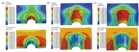
[17][54] used the contour method to measure the two-dimensional residual stress distribution in CE along the crack plane of 7075 aluminum alloy. It was found that the residual stress levels were higher in the mid-thickness of the specimen and lower in compression at the surface; the thickness-averaged residual stresses compressed in the first 2 mm at the edge of the hole and then shifted to tensile residual stresses. According to the available literature, the residual stresses due to the CE of the fastener holes are higher in the middle part of the thickness, and lower compressive residual stresses are generated at the surface (
Figure 46). Due to the asymmetry of the residual stress field across the thickness of the plate, two–dimensional simulations of cold forming cannot accurately estimate the residual stress field
[15][53]. According to the investigation, the compressive residual stresses for SCE fastener holes, in particular, achieved their maximum values and become more compressive with increasing plate thickness for a certain degree of expansion
[18][55].
Figure 46. Von Mises stress under different thicknesses. (
a) 6 mm; (
b) 8 mm; (
c) 10 mm
[8][33].
1.5. Initial Hole Diameter
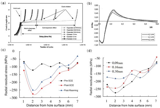
In the SCE process, as most of this process is used in a one-time expansion process, when the expansion is over, the material after elastic-plastic deformation, elastic deformation release, or even reverse yielding phenomenon should be calculated. After the selected expansion amount, the accurate knowledge of the amount of material rebound, to set the hole diameter of an expansion, is needed to achieve the basic assembly requirements. The service life increases as the diameter of the hole increases. This outcome is well known because fracture retardation occurs when the hole diameter rises and the stress concentration factor kt falls, reducing the driving power for crack initiation (
Figure 57a,b)
[7][18]. Yasniy et al.
[19][56] found that for the same degree of CE, the increase in hole diameter was accompanied by an increase in the plastic deformation of the metal around the hole, partially increasing the residual stress. For various hole sizes and CE levels, a relationship exists between the stress range or maximum stress at the edge of the hole on the specimen inlet side and the fracture initiation life.
Figure 57.
(
a
) Crack length vs. number of cycles; (
b
) evolution of the residual tangential stresses with the different diameters; (
c
) radial residual stress in SCE; (
d) radial residual stress of different reaming values [7][20]. ) radial residual stress of different reaming values [18,57].
1.6. Reaming
The diameter of the hole can also be changed by reaming. During the SCE process, the material is plastically deformed by the force at the large end of the mandrel and the metal is expanded at the open seam, resulting in an axial convex ridge in the wall of the fastener hole. This is usually carried out by reaming to remove the convex ridges in the hole to bring the hole size up to the assembly requirements. Proper reaming of the hole wall can correct the roundness of the hole and remove potential fatigue micro-cracks, ensure the continuity of hole collection and micro-continuity, and improve the fatigue life of the hole
[20][57]. However, the removal of the material will inevitably change the elastic-plastic state of the pore wall material, thereby affecting residual stress and microstructure, as shown in
Figure 57c
[21][58].
Figure 57d shows the effect of different reaming amounts on the residual stress distribution. It can be seen that after reaming, the compressive residual stress along the radial direction of the hole edge shows a trend of increasing and then decreasing, and the compressive residual stress gradually decreases with the increase in the reaming amount. Therefore, the proper amount of reaming will result in maximum residual stress around the fastener holes, thereby maximizing fatigue life.
2. The Effect of Cold Expansion on Fatigue Life
Both residual stress and microstructure can affect the fatigue strength of components. Residual compressive stresses inhibit fatigue crack initiation and propagation; the CE process produces plastic deformation, resulting in grain refinement, increased slip and dislocations and improved fatigue strength of the component. This section summarizes in detail the effects of residual stress and microstructure on fatigue performance.
2.1. Effect of Residual Compressive Stress on Fatigue Life
The mechanism by which CE promotes crack initiation and propagation is through the CE process generating a residual compressive stress field that lowers the stress intensity factor around the hole relative to the stress intensity factor for cracks in no cold expansion (NCE) holes
[22][23][70,71].
At an early stage, the fatigue crack growth (FCG) rate can be given by:
where A and m are materials parameters, ΔK is the stress intensity factor range and ΔKop is the crack opening stress intensity factor range. The stress intensity factor range can be calculated by [24][25][72,73]
where 𝜙 accounts for the increase in stress near the hole due to the presence of the hole, α is the fracture length determined from the hole edge, r is the radius of the hole, F is the elastic-plastic correction factor and w is the width of the plate, which can be given by
Synthesizing Equations (2)–(4), the crack propagation rate can be given by
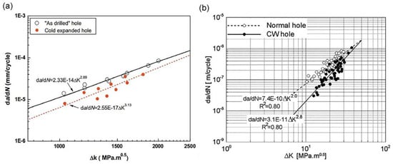
Figure 69 displays the crack extension rate
da/
dN as a function of the different stress intensity components. This comparison unequivocally demonstrates that the crack propagation rate of the CE specimen consistently remains lower than that of the NCE specimen. Due to the residual compressive stresses created by the CE process, which raise the crack open stress intensity factor, the effective stress intensity factor drops
[26][74]. It is suggested that the CE process has a more substantial damping effect on the crack propagation rate when the
ΔK value is low.
Figure 69. da/dN vs.
ΔK plot for NCE and CE hole specimens (
a) TC4
[26][74] (
b) 2024–T3
[27][75].
In recent years, it has been possible to use the modified Goodman relation, as shown in Equation (6), to explain the impact of residual compressive stress on delaying the onset of the fatigue crack. This relationship denotes a linear relationship between stress amplitude and mean stress regardless of the microstructure effect, where 𝜎f is the fatigue endurance of the material under fully reverse loading, 𝜎𝑚 is the mean stress due to the external applied load, 𝜎b is the ultimate tensile strength of material, and 𝜎𝑎 is the equivalent fatigue strength. As a result, fatigue would rise along with the rise in residual compressive stress (𝜎𝑅), extending the fracture initiating life.
The effect of residual compressive stress on the FCG rate at this point can be analyzed using the Paris equation, as shown in Equations (7) and (8):
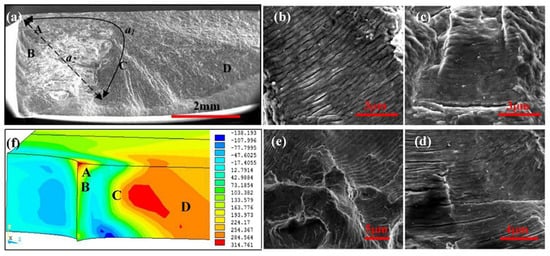
where Δσeff is the effective stress amplitude, σmax is the maximum applied stress, σop is the threshold value of crack opening stress, Δkeff is the stress intensity factor amplitude, kmax and kmin are the maximum and minimum stress intensity factors at the crack, f is a function of component geometry and crack size, a is the crack length, da/dN is the crack growth rate and C and m are material constants. It is obvious that the residual compressive stress, which is treated as a special static, means that stress could minimize the effective stress amplitude Δσeff, and then result in a decrease in the effective stress intensity factor Δkeff at the crack tip and evidently, at last, slow down the FCG rate [26][74]. The striation spacing reflects the FCG rate accurately under cyclic load [28][30]. As a general rule, a smaller striation spacing corresponds to a lower FCG rate [27][29][75,76]. However, the striation spacing is non-uniform owing to complex influencing factors such as the microstructure and load applied. Thus, for an FCG rate in a particular region, an average striation spacing is usually adopted for representation. The stress value aligns with the striation spacing; the greater the stress value, the smaller the striation spacing, as shown in Figure 710. The stress distribution state of the CE specimen during a fatigue test might therefore be interpreted to have been successfully altered by the residual compressive stress produced by CE, leading to an effectively delayed FCG rate compared to the NCE specimen. Yan et al. [26][74] found that the SCE treatment of TC4 produced significant compressive residual stresses that retarded the rate of crack propagation, resulting in a three-fold increase in fatigue life.
Figure 710. Effect of residual stress on FCG rate: (
b–
e) Magnification images for the particular regions of (A–D) in (
a); (
f) Stress counters under fatigue test condition
[30][10].
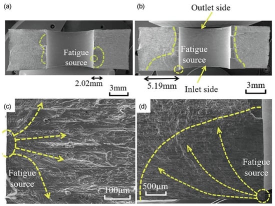
Figure 811 shows that while the crack front of the CE hole is quite uneven, the fracture surface of the NCE hole is regular. Due to the impact of tangential compressive residual stress, the fracture for CE holes expands more slowly down the hole than away from the hole. Because of their propensity to cancel out with the stress brought on by external loading, compressive residual stresses are advantageous because they lower the effective stress concentration at the hole edge
[31][4]. Because the tangential compressive residual stresses on the drilling path of the CE hole increased with time, the crack’s ability to spread was slowed or prevented altogether. However, the SCE specimen is located at the hole entrance, where the strengthening impact is minimal
[32][45]. The material fatigue life is strongly impacted by residual stress, according to Kattoura et al.
[33][77]. It alters the specimen stress state when paired with the fatigue load, which reduces the initiation and growth of fatigue cracks. As a result, the SCE specimen crack started at the hole inlet side, where residual stress was minimal. Additionally, the lengths of the transition area and the major crack extension area were both longer than those of the NCE specimens. This shows that the SCE specimens can withstand more fatigue cycles and have a longer fatigue life.
Figure 811. SEM photos of the fracture surface of 7075-T6 Al alloy: (
a,
c) NCE (
b,
d) CE
[32][45].
Both the beginnings of cracks and the delay in the propagation of cracks are significantly influenced by the magnitude of plastic deformation brought on by compressive residual stress
[7][18]. The magnitude of the plastic deformation after the compressive residual stress that has been decreased by relaxation treatment or fatigue loading determines the fracture propagation delay. With increasing distance from the hole edge, the material plastic deformation lessens
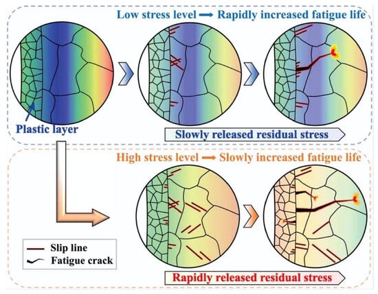
[33][77]. The compressive residual stress brought on by SCE may dramatically lessen crack initiation and propagation during fatigue testing when the material is under less stress (
Figure 912). When under increasing stress, the fast release of residual stress at the holed root results in a subtle improvement in fatigue life. Additionally, the substantial plastic deformation created at the holed root under the greater stress level makes it harder for the plastic layer to block fatigue fracture
[34][59].
Figure 912. Illustration of the fatigue failure mechanisms of the CE specimen in a schematic
[34][59].
2.2. The Effect of Microstructure on Fatigue Life
Numerous dislocations are produced as a result of the CE process in plastic deformation. As the degree of deformation rises, slippage and an increase in dislocation density take place. When dislocation lines encounter defects, particles and other obstacles, dislocation entanglement occurs and dislocation walls are formed. Faghih et al.
[35][47] found that at high CE concentrations inter-granular defects were found in the microstructure. Defects are present because of generated excessive plastic deformation, which causes grain slippage
[36][78]. Dislocations gather along grain boundaries or nanoprecipitation during expansion due to the significant plastic deformation surrounding the fastener hole, which hinders dislocation mobility and stops additional plastic deformation, increasing hardness.
In addition, grain boundaries (GB) can inhibit short crack extension, and changes in the crystal orientation of adjacent grains can lead to the tilting of the crack face
[35][37][47,79].
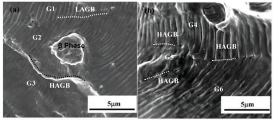
Figure 103 divides the GB into six regions and illustrates the effect of changes in GB and adjacent grain crystal orientation on FCG for AA6061-T6 holes. If the favorable slip plane of the adjacent grains is essentially in the same plane, the crack can be transmitted directly or indirectly from one grain to the other. On the other hand, if there is a deflection angle in the favorable slip plane of the adjacent grains, this can lead to tilting of the crack plane. Obviously, crack tilting or distortion favors FCG closure, resulting in longer fatigue life
[36][78].
Figure 103. Effects of secondary particles and grain boundary (GB) on crack growth: (
a) Crack propagating though the low angle grain boundary (LAGB) smoothly andsuppressed by the precipitation strengthening phase of SiMg2; (
b) Crack turning inhigh angle grain boundaries (HAGB)
[30][10].
As demonstrated in
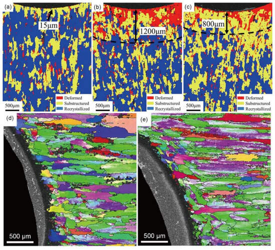
Figure 114, there is a clear deformation structure in the surface area on both sides, which is no longer the original recrystallized grain. Grain refinement is visible at the location of the expansion holes. As shown in
Figure 114a–c, in contrast to the large grains distant from the SCE holes, which remain unchanged, a significant number of LAGB are produced within the large grains close to the fastener holes, generating fine sub-grains
[38][19]. During grain refinement, more grain boundaries and sub-grain boundaries are created. These grain boundaries can stop fatigue cracks from spreading and significantly enhance fatigue performance
[39][80]. Particularly in the X-direction (
Figure 114d,e), the wall around the holes in SCE underwent extensive sub-grain refinement, resulting in the formation of numerous grain boundaries. Short crack growth may be hampered by these grain boundaries. A limited amount of plastic deformation will occur with hindered dislocation buildup if the dislocation slips to the grain boundary and is prevented by the grain border
[30][10].
Figure 114. Local misorientation average angle and deformation distribution map, 7075-T6: (
a) NCE specimen of 7075-T6; (
b) outlet side of SCE specimen; (
c) inlet side of SCE specimen; (
d,
e) inlet side of SCE specimen of 7075-T651 in the radial direction and tangent direction
[32][40][45,81].
SCE treatment produces a gradient effect on grain refinement
[6][44]. The formation of the gradient layer is associated with diverse plastic deformations at different depths in the SCE process. During deformation, dislocation slip is primarily responsible for the particle refinement that increases the strength of the material and improves its resistance to fatigue crack initiation
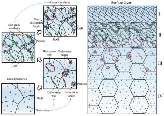
[41][42][82,83]. The construction of the gradient nanostructure using the SCE approach is shown in
Figure 125. The gradient structure can effectively prevent the spread of cracks
[43][84].
Figure 125. Schematic showing the process by which gradient nanostructures are formed after the SCE process
[32][45].