1. Additive Manufacturing
Additive manufacturing (AM) is a very promising manufacturing method that has been under research for a long time now. Yet, parts made by AM are still considered critical because of the large number of different AM technologies and their specific influences on the process and material, which significantly affect the mechanical properties. The currently available testing standards for conventional manufacturing methods (such as rolling, sheet metal forming, or machining) were considered. Newer technologies develop much faster than testing methods and the gathering of reliable results
[1]. Therefore, derived guidelines and standards for testing AM processes and parts take a lot of effort and time to be drafted and evaluated. Especially for high-risk applications such as the aviation industry, the qualification procedure for the manufacturing process, the processed material, as well as the part/material testing method is a time- and cost-consuming progress
[2]. At the moment the known testing standards are adapted for the testing of AM parts
[3][4][3,4].
Two widely spread AM methods are Laser Powder Bed Fusion (L-PBF) and Wire Arc Direct Energy Deposition (WA-DED), which share the same layer-wise deposition principle. L-PBF is realised by distributing powder of a specified layer thickness with a coater on a moveable building platform. A laser source is used to melt the previous solid layer together with the distributed powder. The desired geometry is generated by guiding the laser via a high-speed mirror system. After finishing one layer, the platform moves downwards and the process cycle starts again. The most influential process parameters for L-PBF are the laser power, laser scanning speed, laser spot size, powder layer thickness, and hatch distance. A derived influence of the previously mentioned parameters is the transient temperature field, which also depends on the platform pre-heating or powder bed temperature, the thermal material properties, and the part geometry
[5]. WA-DED instead uses conventional welding equipment like that for Gas Metal Arc Welding (GMAW). Here, a consumable electrode as filler wire is fed to a substrate plate. An electric arc, used as an energy source, melts the wire and the already deposited weld beads while generating a new layer. The control of the machine movement to generate the desired part geometry is mostly realised via NC code processed by a CNC machine or a robot. The process parameters with the most influence are the welding power, welding speed, and shielding gas composition
[6][7][8][6,7,8]. Up to date, a wide range of possible AM processes covering different materials and energy sources are available. For different AM principles, a certain terminology is used. Yet, there exist manufacturer-specific individual process names. A more detailed description of those processes and the applied terminology can be found in
[9][10][9,10].
AM processes need to be qualified to ensure the production of defect-free parts and the achievement of desired (minimal) mechanical properties like ultimate or yield strength. The easiest, and at the beginning of a qualification process the most informative testing method, are static tensile tests. The often-chosen geometries are therefore near net-shape geometries of tensile test samples or simple walls, where tensile test samples are extracted from. Further test geometries are specific, e.g., bending and shear or also crack propagation, which are also further separated in static and dynamic loads.
Complex AM parts, however, can experience combined tensile, compressive, bending, and shear loads at the same time. This causes a multi-axial load that can be calculated by equivalent stress, such as Von Mises
[11]. The AM parts are usually tested in a testing rig that simulates the real operation conditions. While this allows for proving of the stability of the final AM part, a distinguished determination of strength for each different mechanical load (e.g., bending and shear strength) is not possible. Yet, those parameters are required for a sufficiently accurate design and simulation process.
2. Investigation of the Obtained Mechanical Properties by Destructive Test Methods
The testing of AM parts with their final geometry and under real operation conditions has not been widely common in the research area so far. The VDI 3405.2 provides guidelines for conducting a range of tests aimed at determining standard material parameters for additive manufactured parts
[12]. The following section contains a detailed analysis of commonly used tests such as tensile, compression, and Charpy notched bar impact tests, followed by application-related tests such as bending or multiaxial loads, all of which allow for conclusions to be drawn about the quality of the components and the reliability of the processes in additive manufacturing.
The majority of researchers conduct
tensile tests using standard geometries, such as those outlined in standards, e.g., ASTM or DIN/ISO. In the standard DIN EN ISO/ASTM 52927-14 (draft) are stated general principles for testing AM parts
[13]. The standard also includes the stock material, geometrical, and surface aspects as well as load type and sample preparation methods for AM parts. An often-generated part geometry is a turbine blade, where tensile test specimens are extracted. Posch et al. used WA-DED to produce a blade-like geometry made of duplex stainless steel. They extracted tensile test samples from different regions of the blade-like geometry and showed that they have comparable mechanical tensile properties according to the material specification in an as-welded condition
[14]. Liu et al. used WA-DED to repair a Ti6Al4V blade and obtained mechanical tensile properties for the as-welded condition, which are in the range of other manufacturing processes
[15]. Yan et al. demonstrated the Laser Metal Deposition (LMD) process for a Ti6Al4V blade, where lower mechanical tensile properties than for WA-DED and the casting condition TC4 were achieved
[16]. Rodriguez et al. showed the influence of the tensile test sample orientation and the bead orientation for a stainless-steel WA-DED part. They demonstrated that vertically oriented samples (beads perpendicular to the tensile test sample orientation) have a lower ultimate strength and yield strength than horizontally oriented samples (beads parallel to the sample orientation)
[17]. Addison et al. examined the WA-DED process for a Ti6Al4V thin wall with a height of 155 mm. No influence of the extraction position (top or bottom) on the mechanical properties could be determined
[18]. Bambach et al. manufactured a Ti6Al4V hybrid part by forming a preform and subsequent WA-DED to enhance the geometry. They stated that the obtained tensile mechanical properties exceeded the requirements according to DIN standards for casted and forged material
[19]. Köhler et al. extracted tensile test samples from an aluminium wall made by WA-DED and also demonstrated that no significant influence on the tensile properties can be derived from the extraction height if the interlayer temperature is kept constant below the material’s maximum, but that it depends on the loading direction regarding the bead orientation
[20]. Yildiz et al. created thin walls and a large prismatic block of low-alloy steel by means of WA-DED and determined the tensile properties as well as the hardness distribution. They showed that tensile strength is only slightly affected by heat input but is more so affected by sample orientation. Nearly the same tensile strength values were achieved by both the thin walls and the block. The hardness varies maximally around 20% for the thin wall, depending on the distance to the substrate. At half the height, the hardness has a global minimum, while the bottom and top parts have higher hardness values. For the block, the hardness slightly increases from the bottom to the top of the block with a deviation of about 10%
[21].
Compression tests can be applied either to larger parts to simulate massive forming processes or to small samples to gain knowledge of microstructure development. In both cases, the forming behaviour is analysed as a crucial material parameter. Longhitano et al. investigated L-PBF-manufactured Ti6Al4V parts under tensile and compressive loads for biomedical applications, where a different material behaviour between tensile and compressive loads was observed. A heat treatment led to sufficient mechanical properties for use in implants by meeting ASTM requirements
[22]. Abbaszadeh et al. analysed the results of the compression behaviour of WA-DED structures for different materials. They showed material-dependent anisotropic behaviour
[23]. Bambach et al. examined the hot forming behaviour of Ti6Al4V made by AM. The findings allow for the design of optimised processing routes, which shall reduce forming forces and improve mechanical properties
[24]. The buckling that occurs during compression load is often examined for lightweight-designed L-PBF parts. Clausen et al. state that the buckling load depends on the infill material and can be increased by optimisation
[25]. Nazir et al. demonstrated the influence of design parameters on the buckling behaviour of lattice structures. Vertical beams have a higher tendency of buckling than horizontal or inclined beams. Also, the infill density is a significant design parameter
[26]. Vastola et al. showed the impact of smooth corners that lead to a reduction in distortion. Also, the part width has a stronger impact on the distortion than the part height. Furthermore, a tubular cross-section causes significantly less distortion than a square-like cross-section
[27].
The method of
notched bar impact testing, as outlined in the DIN EN ISO 148 series of standards and commonly employed in both scientific and practical contexts, serves to determine the energy of notched bars under impact loads and consequently their corresponding behaviour
[28]. The authors, Š. Hermanová et al., carried out a study on components manufactured through powder bed-based additive methods using 316L material. The study aimed to determine the maximum notched impact energy of these components
[29]. Deng et al. (2019) performed a similar study and made a distinction between specimens that underwent heat treatment at 650 °C and those that did not
[30]. In their study
[31], Davies et al. conducted comparable investigations wherein they analysed samples taken both horizontally and vertically in their original state, as well as after undergoing heat treatments at 700 °C and 900 °C. Komorasamy et al. accomplished a comparative analysis of the behaviour of notched bar impact specimens extracted horizontally and vertically with respect to the direction of exposure as per DIN EN ISO 148 on Inconel 718
[23]. Yasa et al. examined the notched bar impact strength of L-PBF produced parts made of 316L, Ti6Al4V, and maraging steel. Here, they used a cuboid testing geometry with and without notches. The varied process parameters were the building orientation (x, y, z) and heat treatment. They found that the preparation (conventionally or by electrical discharge machining, EDM) of the notch and the building orientation showed no significant influence on the toughness
[32]. Afkhami et al. investigated the influence of the weld orientation vertically and horizontally to the notch and found that there is no correlation
[33].
The following are some notes on application-related tests that allow conclusions to be drawn about the quality of the additive manufacturing process. Ayan et al. used tensile test geometries to examine the
bending fatigue properties of structural steel produced by WA-DED
[34]. Concli et al. investigated the bending fatigue behaviour of 17-4PH gears produced by AM. They used a single-tooth bending fatigue approach to determine the bending strength. They found good bending strength without any further treatment but highlighted the importance of defects, which negatively affect the gear
[35]. Schmitt et al. also applied dynamic mechanical testing to a gear made of 16MnCr5 processed by L-PBF to determine the tooth root bending strength. They showed that the achievable tooth root strength lies closely under the value of a conventional gear made of case-hardened steel. Additionally, this also showed the influence of the sample orientation, manufacturing process, and post-treatment on the tensile strength, which showed larger deviations
[36].
Torsional fatigue behaviour of wrought and AM Ti6Al4V was examined by Fatemi et al. They showed the effects of different manufacturing processes, additional heat treatment, and surface conditions
[37]. Furthermore, Fatemi et al. provide a novel sample geometry for fatigue testing of AM parts. Here, axial, torsion, and combined axial-torsion loads were applied to a hollow thin-walled sample. Experiments showed the general feasibility of the novel sample geometry without any significant negative effects of the geometrical shape on the fatigue life compared to conventional tensile test samples
[38]. The effect of combined multi-axial bending and torsion on fracture surface parameters was examined by Macek et al. for high-strength steels produced by conventional and additive manufacturing. They state that surface topography parameters are influenced by the bending-to-torsion ratio and the fatigue life, as well as the von Mises stress range, all in a linear relationship
[39]. Fatemi et al. also comprehensively examined the multi-axial fatigue behaviour of additively manufactured Ti6Al4V and 17-4PH
[40].
Bambach et al. conducted a study involving mechanical load testing on a thread that was cut into an aluminium sheet that had been thickened through the use of laser metal deposition (LMD). A comparative analysis showed a statistically significant increase in the pull-out force of the AM-thickened sheet after subsequent curing by almost four times compared to the original sheet
[41].
3. A Comparative Analysis of Manufacturing Technologies with Respect to Their Impact on Mechanical Properties
In some cases, tensile test results of ultimate strength or yield strength can be used to roughly estimate other mechanical properties such as bending strength. In general, the mechanical properties are empirically determined and individually proven but are not mathematically related to the manufacturing processes that define the geometrical shape.
A comprehensive overview of mechanical property gradients in AM parts and specimens is given by Kok et al. They state that anisotropic behaviour and heterogeneity are significantly affected by microstructural development, including grain morphology, crystallographic texture, lack-of-fusion defects, phase transformation, heterogeneous recrystallization, layer banding, and microstructural coarsening. While the requirements for the mechanical properties are often met, larger local variations in the strength parameters occur due to different building directions and AM process parameters
[42].
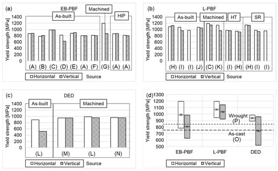
For demonstration purposes, the variation in the yield strength depending on the manufacturing process and material condition of the data summarized by Kok et al. is shown in Figure 1 for Ti6Al4V.
The figures reveal the large deviations in the yield strength depending on the manufacturing process (Electron Beam Powder Bed Fusion (EB-PBF), L-PBF, DED), the material condition (as-built, hot-isostatic pressed HIP, machined, heat treated HT, stress relieved SR), and the testing direction, even for standardized materials. In relation to Kok et al., and in accordance with ASTM F F1108
[57] and ASTM 1472
[58], the reference values for yield strength for the as-cast condition is 758 MPa and for the wrought condition 860 MPa
[42].
The yield strength in horizontal orientation of as-built samples shows a minimum of 783 MPa for Electron Beam Powder Bed Fusion (EB-PBF)
[44] and a maximum of 1093 MPa by DED
[50]. In vertical orientation, there is a range of 603 MPa between the minimum of 522 MPa by Powder Bed Fusion
[54] and the maximum of 1125 MPa by DED
[50]. Machining of the specimens improves the mechanical properties of the specimens due to the reduction in the notch effect. The minimum yield strength in horizontal orientation is 950 MPa by L-PBF method
[55] and maximum yield strength is 1195 MPa by the PBF and the DED method. In vertical orientation, the characteristic values are between 869 MPa by the PBF method and 1143 MPa by the DED
[45]. Heat treatment and stress relief annealing were only performed for the DED process. In horizontal orientation, the heat-treated samples obtain a minimum yield strength of 944 MPa and a maximum yield strength of 973 MPa
[53]. In vertical orientation, yield strengths are between 937 MPa
[50] and 964 MPa
[50]. Stress relief annealing produces yield strengths between 958 MPa
[51] and 1145 MPa in horizontal orientation
[50]. In vertical orientation, the yield strength ranges between 937 MPa
[51] and 1132 MPa
[50]. Hot-isostatic pressing was only investigated for the EB-PBF process. The yield strength in horizontal orientation varies between 814 MPa and 866 MPa. In vertical orientation, yield strengths vary between 807 MPa and 868 MPa
[50]. The minimum and maximum values of achievable yield strength over different manufacturing processes are shown in
Figure 1d. Here, the large general range is visible, which can vary from approx. 520 MPa up to 1200 MPa. In some cases, the requirements of ASTM standards are not met.
The impact of the component geometry on mechanical properties is a well-known phenomenon that is duly considered in component design through the incorporation of notch and shape factors. The aforementioned factors enable the capture of distinct stress distributions, local plastic strains, notch effects, and inhomogeneous microstructure development, thereby obviating the need for component-specific tests during the design phase
[59]. However, incorporation of the manufacturing process as a design factor is currently not feasible even for materials that are extensively utilized. So far, only surface treatments (e.g., shot peening) and/or heat treatments (e.g., induction heating) that can improve mechanical properties have been used as multiplicative factors in a range of 0.8–1.4 for the calculation
[59]. These factors are only applicable to the calculation of fatigue strength.
Due to the different material behaviours in a wide range during AM processes, a distinction of the process-specific influences of different AM processes on the microstructure evolution andmechanical properties are challenging, respectively. As the manufacturing process has a significant impact on the final mechanical properties, it is of high interest to know which AM process leads to which microstructures and mechanical properties and what the causing mechanisms are. This knowledge about the relationship between mechanical properties and the AM process is strongly required for the design of parts. Furthermore, there is a lack of statements for basic design elements in a part geometry that are dependent on the entire manufacturing process, which typically consists of multiple processing steps.