Grid-Forming Control Approaches: Comparison
Please note this is a comparison between Version 2 by Jason Zhu and Version 3 by Jason Zhu.

Changes are being implemented in the electrical power grid to accommodate the increased penetration of renewable energy sources interfaced with grid-connected inverters. The grid-forming (GFM) control paradigm of inverters in active power grids has emerged as a technique through which to tackle the effects of the diminishing dominance of synchronous generators (SGs) and is preferred to the grid-following (GFL) control for providing system control and stability in converter-dominated grids.Β 

  • grid forming
  • inverter control
  • low inertia
  • universal grid-forming control
  • inverter-dominated grid

1. Introduction

Generally regarded, the GFM structure is made up of inner control loops for voltage and current and an outer power synchronisation loop that implements the grid-forming control mechanism, depending on the method of preference [1][2]. A current-limiting algorithm may be implemented between the voltage control and the current control to prevent current overloads and keep the solid-state devices within allowable operational margins.
The inner control loops of the GFM may be implemented in single-loop, multi-loop, or open-loop frameworks [3]. When implemented in a multi-loop framework, the voltage and current loops are implemented, serving different purposes. The voltage loop regulates converter voltage and incorporates virtual impedance, while the current loop regulates the damping of LC filters, as well as overcurrent limitation [4]. Multi-loop control loops implement better harmonic rejection, resonance damping, fault-handling ride-through capability, and mode transition capability, compared to single-loop or open-loop implementations [5] The design of controllers strives to achieve a large control bandwidth and phase margins, which guarantee stable performance over a wide range. The adoption of each implementation framework has its merits over the others. For example, in [5], triple loops were used to provide the converter with a large bandwidth; in [6], the single-loop implementation was shown to perform better in motor inrush current mitigation, when compared to double-loop GFM controllers.
These controllers are preferably designed in the synchronous reference frame (π‘‘π‘žβˆ’) or the stationary frame (π›Όπ›½βˆ’), to transform a sinusoidal tracking problem into a DC tracking problem, which provides a robust design of controllers with suitable fidelity, bandwidth, and small errors, achievable with a simple controller design [7][8].
The primary structure of GFM control should provide dynamic synchronisation ability to an arbitrary grid and maintain the voltage magnitude and phase at the PCC for the entire range of load demands from the grid, without loss of synchronisation within the electrical and thermal limits of the inverter and its storage capacity [9].

2. Droop Control

Droop control is the simplest control adopted for connecting parallel inverters in active power networks, through adopting the steady-state power-sharing droop capabilities of SGs [10][11] Droop control depends on the steady-state relationships of active power (𝑃) and angular frequency, and reactive power (𝑄) and voltage difference in a predominantly inductive network, and may suffer instability due to power coupling in highly resistive networks, unless they are designed with alternative behaviours.
Droop control emulates synchronous generator governor control in the frequency control of inverters, establishing a negative feedback relationship between real power and frequency, and may incorporate a degree of inertia [1][7] The droop law is shown in Equation (1).
where
πœ”=πœ”π‘ π‘’π‘‘βˆ’πΎπ‘(π‘ƒβˆ’π‘ƒπ‘ π‘’π‘‘) (i)π‘‘πœƒπ‘‘π‘‘=πœ” (ii)

where

πœ”

is the instantaneous angular frequency,

πœ”π‘ π‘’π‘‘

is the angular frequency reference,

𝑃

is the power output of the converter,

𝑃𝑠𝑒𝑑

is the reference power,

𝐾𝑝

is the

π‘ƒβˆ’πœ”

droop coefficient, and

πœƒ is the power angle.

is the power angle.

Given the relationship between angular frequency and power angle, shown in Equation (1)(ii), active power may be drooped with angular frequency πœ” or power angle πœƒ. Angle droop has been adopted in some applications, due to the limits imposed on frequency in frequency regulation in a network with frequent load changes [12]. In the case of angle droop,
πœƒ=πœƒπ‘ π‘’π‘‘βˆ’πΎπ‘(π‘ƒβˆ’π‘ƒπ‘ π‘’π‘‘)

where πœƒπ‘ π‘’π‘‘ is the set value of the power angle, 𝑃 is the real power output of the inverter, 𝑃𝑠𝑒𝑑 is the reference power value, and 𝐾𝑝 is the π‘ƒβˆ’πœƒ droop coefficient.

The voltage droop is established to ensure reactive power sharing in the voltage magnitude loop, also imposing a negative feedback relationship between the reactive power and the voltage magnitude, according to Equation (3), as follows:
𝑉=π‘‰π‘ π‘’π‘‘βˆ’πΎπ‘ž(π‘„βˆ’π‘„π‘ π‘’π‘‘)

where 𝑉 is the instantaneous voltage, 𝑉𝑠𝑒𝑑 is the voltage reference, 𝑄 is the instantaneous reactive power, and 𝑄𝑠𝑒𝑑 is the reference reactive power.

When the controller is set in the π‘‘π‘žβˆ’π‘“π‘Ÿπ‘Žπ‘šπ‘’, the π‘‘βˆ’ and π‘žβˆ’ components of the voltage are defined according to Equation (4), as follows:
𝑉𝑑=π‘‰π‘‘βˆ’π‘ π‘’π‘‘βˆ’πΎπ‘ž(π‘„βˆ’π‘„π‘ π‘’π‘‘)π‘‰π‘ž=0
The value of π‘‰π‘ž is set to zero to assume that the π‘‘π‘ž frame is aligned with the stationary reference frame at the PCC. The reactive power loop prevents the circulation of reactive current between inverters while maintaining a predefined voltage magnitude, according to the π‘„βˆ’π‘‰ droop Equation (5).
Droop control is related to virtual synchronous machine control in a steady-state system [13] and has been proven to emulate inertia using low-pass filters in its power loops [14]. Correlations between angle droop, virtual impedance, and frequency droop were derived in [15], showing that angle droop is effectively a virtual inductance method, virtual inductance is a frequency droop method with derivative feedback, and virtual inductance and frequency droop, when combined, enhance oscillation damping in a proportional derivative manner. A comparison of the performance of single-loop and multi-loop droop controllers was performed in [16], showing the better performance of single-loop over multi-loop controllers in small-signal stability, due to the larger inner coupling reactance of the controller.
Droop controllers may face inaccuracy issues with power sharing, in highly loaded and high-impedance systems with varied line impedances between controllers, which may lead to the prioritisation of frequency and voltage regulation over power droop operation. To address this issue, the droop controllers in a microgrid were optimised in [17] following a multi-objective evolutionary algorithm to obtain a frontier of optimisation, from which the solution was chosen using the fuzzy affiliation function.
Droop variants proposed in the literature address the limitations of conventional droop that arise due to assumptions in its formulation, which include purely inductive network (high X/R ratio) coupling, decoupled voltage and frequency control, and simple networks with constant impedances. Therefore, controllers may be optimised using heuristic algorithms [18] or variants of the conventional droop used. In [19], the various droop control variants present in the literature were compared, including transient droop, angle power feedforward droop, and the virtual frame transformation droop.
Droop control used for steady-state power sharing in electrical grids [20] is implicitly incorporated in all grid-forming control techniques in their steady state [21], regardless of their unique designs and transient characteristics.

3. Power Synchronisation Control (PSC)

First presented in [22], this control mechanism was designed to use the transient power transfer mechanism of synchronous generators in voltage source converters (VSCs) to achieve active power control in weak grid HVDC applications [23][24]. The principle employs the relationship between the change in power (and torque) at the generator output and the angular frequency of the voltage phasor (and hence phase angle) when synchronous generators restore their synchronism after a disturbance in a connected system.
The PSC control law is as follows:
π‘‘βˆ†πœ—π‘‘π‘‘=π‘˜π‘(π‘ƒπ‘Ÿπ‘’π‘“βˆ’π‘ƒ)

where πœ— is the electrical angle, π‘˜π‘ is the controller gain, 𝑃 is the instantaneous active power, and π‘ƒπ‘Ÿπ‘’π‘“ is the reference of active power.

The PSC controller contains a high-pass filter and an embedded current controller that limits current during transients, which grants it a preferable advantage to operate in weak grids, as initially designed [22].
The transient stability of the PSC is related to the power angle dynamics of a converter, which affect the gain and bandwidth of the controller. Therefore, a PSC faces transient instability in weak grids, due to the higher power angle dynamics affecting its gain and bandwidth [25]. The PSC was designed for VSCs operated in weak grids, but faced operational challenges under those conditions, due to the large load angles, and needed to run a low controller bandwidth to maintain a stability margin. The challenge of achievable bandwidth was further proven through the analysis methods in [26]. This challenge was also addressed in [27], in which the active power loop was cascaded with the DC-link voltage loop design for a desirable bandwidth and stability margins, following a robust design that quantified the closed-loop transfer function, allowing for the design of the gain of the DC-link control loop. The design was reported to provide controller stability for all grid strengths and operational conditions.
The problems of low bandwidth and synchronous frequency resonance in PSCs operating in inductive grids was addressed in [28]. Using small-signal stability analysis, the dynamics of grid impedance on the power loops revealed that a slight resistance in the grid impedance and the non-minimum effect of loop gains on the phase caused synchronous frequency resonance. The conjugate pair poles in the open loop, due to the grid impedance, were eliminated using the analytics branch method in the power loops, which stabilised the controller by nullifying the non-minimum phase effect of the loop gains. The proposed method was reported to perform better than virtual resistance methods.
In [29], the transient stability of a PSC was performed using the phase portrait method. The system was modelled as a first-order system and was observed to possess better transient dynamics, as compared to SGs. The overdamped nature of the PSC grants it stability after a disturbance if equilibrium points exist. However, in cases for which no equilibrium points exist, and the VSC loses synchronism due to a fault, resynchronisation is possible after one cycle if the fault is cleared after the critical clearing time.
In [25], a deep neural network machine learning approach was used to detect the transient stability of a PSC using voltage sag severity and duration, the grid characteristics, and the operating point of the converter as data points for the learning process. This detection system was incorporated into the power synchronisation loop and fitted with a corrective mechanism that freezes the phase to keep the converter synchronised during faults.
An internal model with a one-degree-of-freedom structure was adopted for the PSC in [30] to minimise the plant error in the small-signal model of the controller to deal with the effects of non-minimal phase dynamics that affect the stability of a PV-based converter. This resulted in better tracking capabilities of the controller in weak grids, with seamless transitioning between island and grid-connected modes.
The control of a PSC using proportional-integral-derivative (PID) controllers was proposed in [31] to eliminate non-minimum phase phenomena in the small-signal model of the controller. This PID was tuned for robustness during voltage imbalances and frequency oscillations by adopting the power–frequency swing equation of the synchronous generator and a high-pass filter.

4. Synchronous Machine Emulation Controllers

To facilitate the seamless operation of controllers in a machine-dominated grid, controllers are designed to resemble the performance aspects of synchronous machines. The full-scale machine model is a high-order electrical and mechanical model that is not fully replicable in controllers, with only the relevant components for frequency and voltage regulation used in the required application. The power synchronisation loop is designed for machine emulation to provide the angular frequency (and power angle) by incorporating control algorithms used in the SG excitation, governor, and rotor.

4.1. Virtual Synchronous Generator (VSG) Control

The VSG was proposed to combat the high RoCoF effect observed in grids with increased penetration of inverter-based resources. To replace the rotating masses of synchronous machines, the emulation of rotor dynamics through electronic controllers was proposed first in [32]. The VSG, therefore, emulates the rotor (swing equation) and governor dynamics of the SG.
The formulation of VSG control includes governor dynamics that establish the necessary steady-state droop characteristics and a rotor dynamic that includes damping and inertia coefficients whose implementations are pertinent to the behaviour of the design [33][34][35][36][37]. The VSG dynamics are obtained through Equation (6), as follows:
π½π‘‘πœ”π‘‘π‘‘=1πœ”0(π‘ƒπ‘ π‘’π‘‘βˆ’π‘ƒπ‘’)βˆ’π·π‘(πœ”βˆ’πœ”0)𝑃𝑠𝑒𝑑=π‘ƒπ‘Ÿπ‘’π‘“+𝐾𝑝(πœ”βˆ’πœ”0)π‘‘πœƒπ‘‘π‘‘=πœ”

where πœ” is the angular frequency, πœ”0 is the set value of angular frequency, πœƒ is the electrical angle, 𝐽 is the inertia constant, 𝐷𝑝 is the damping coefficient of the rotor dynamics, 𝐾𝑝 is governor stiffness factor, 𝑃𝑒 is the electrical power supplied, 𝑃𝑠𝑒𝑑 is the set value of power, and π‘ƒπ‘Ÿπ‘’π‘“ is a variable calculated in the controller, derived as shown in Figure 1.
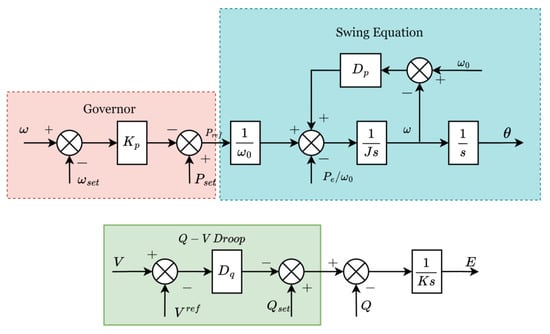
Figure 1. The virtual synchronous generator (VSG) controller.
The reactive power regulation is dictated through the following relationship:
𝐾𝑣𝑑𝑉𝑑𝑑=π‘„π‘ π‘’π‘‘βˆ’π‘„βˆ’π·π‘ž(π‘‰βˆ’π‘‰π‘Ÿπ‘’π‘“)

where 𝐾𝑣 is the voltage integral gain, 𝑄 is the instantaneous reactive power and 𝑄𝑠𝑒𝑑 its set value, and 𝐷𝑝 is the π‘„βˆ’π‘‰ droop coefficient of the controller.

The VSG is a virtual inertia implementation of the conventional droop function and uses this inertia derivable from energy storage to enhance the stability of the grid [38].
The limitations of the VSG stem from the implementation of mechanical control dynamics in an electronic setup. For example, SGs use the power system stabiliser unit for oscillation damping, whereas VSGs face oscillations when connected to the grid [39]. The advantage of using the VSG is its controllability, shown in the flexibility of designing the coefficients 𝐽 and 𝐷𝑝 for the desired inertia and damping responses, unlike the SG, which is limited by its physical characteristics [40].
The steady-state, transient, and synchronisation stability characteristics of the VSG are of interest, given that it is an attractive GFM control through which to combat the issue of reduced inertia in grids [41], with areas such as damping [42], resonance and oscillations in weak grids [43], virtual resistance [44], system representation [45][46], decoupling for oscillation mitigation [47], and the effects of grid conditions [48] being investigated extensively.

4.2. Synchronverter

In the initial design of grid-connected inverters, the motivation was to design a controller whose interaction with the power grid was minimal. The synchronverter is, therefore, designed to mimic the SG by emulating the governor, rotor, and exciter dynamics to provide controllability to factors that affect performance, such as inertia, friction, damping, and inductance, which the electronic control provides when compared to the rigid control of the SG [49].
The synchronverter is defined in Equation, as follows:
ΞΈ Β¨ = 1 J T m βˆ’ T e βˆ’ D p ΞΈ Λ™ T e = M f i f i , sin ΞΈ ~ e = ΞΈ Λ™ M f i f sin ΞΈ ~ P = ΞΈ Λ™ M f i f i , sin ΞΈ ~ Q = βˆ’ ΞΈ Λ™ M f i f i , cos ΞΈ ~ cos ΞΈ ~ = cos ΞΈ cos ΞΈ βˆ’ 2 Ο€ 3 cos ΞΈ + 4 Ο€ 3 , Β  sin ΞΈ ~ = sin ΞΈ sin ΞΈ βˆ’ 2 Ο€ 3 sin ΞΈ + 4 Ο€ 3 .

where πœƒ is the electrical angle, with πœƒΒ¨=𝑑2πœƒπ‘‘π‘‘2, πœƒΛ™=π‘‘πœƒπ‘‘π‘‘; 𝐽 is the moment of inertia, 𝐷𝑝 is the damping factor, also designed for droop functionality [50]; π‘‡π‘š is the mechanical torque; 𝑇𝑒 is the electrical torque; 〈.,.βŒͺ represents the inner product; 𝑀𝑓 is the mutual inductance; 𝑖𝑓 is the excitation current of the stator; 𝑒 is the electromotive force; 𝑃 is the real power; 𝑄 is the reactive power; and 𝑖 is the stator current.

The power synchronisation loop of this controller [51] is as follows:

where 𝑃0 and πœ”0 are the nominal values for real power and angular frequency.
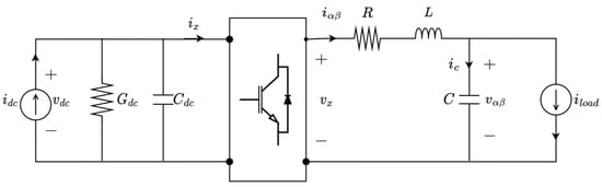
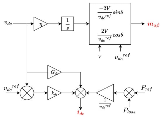
Initial synchronverter designs included a synchronisation unit, such as a PLL, to provide grid frequency and voltage references. A self-synchronising synchronverter is proposed in [52] through the introduction of a switching algorithm in the controller structure, operated to eliminate the synchronising unit, thus making the synchronverter structure simple. The stability of the synchronverter in [49] was improved in [53] through modification of the field current control for fault handling, improved filters for better grid connection, changes in the torque to incorporate losses and provide better power tracking, and incorporation of a virtual capacitor to filter DC components. A detailed analysis of a 5th-order synchronverter connected to an infinite bus was carried out in [54], investigating the necessary conditions for its local asymptotic stability using equilibrium points in the two-dimensional power plane.
The modification of the synchronverter, the effects of its parameters, and its applications were addressed in [55], presenting the effects of parameter tuning, based on proposed methods in the literature, on the eigenvalue-based analysis of stability. A synchronverter was designed in [56] to mitigate voltage imbalance in STATCOMs through supplying oscillating power locally in order to compensate for negative sequence voltage, illustrating the use of GFM inverters to improve power quality.

5. Matching Control

While power synchronising controllers assume decoupled DC and AC sides of a DC-to-AC power converter [57], with their synchronisation based on active power transfer emulating SGs, matching control is developed upon the measurement of the DC voltage at the DC bus of the inverter to indicate frequency balance on the AC side, which effectively couples the control of the AC frequency to the DC voltage [58]. The DC bus voltage, a form of energy storage in an inverter, fluctuates to indicate power transfer, and the control thereof can be utilised to effectively control active power transfer. Matching control is therefore designed to utilise the device-level similarities between power converters and synchronous machines [59].
By considering the averaged 3-phase model of a converter, given as a linear AC and DC circuit coupled with a nonlinear modulation block representing the 6-switch 2-level inverter, as shown in Figure 1, and matching its dynamics to those of a single pole pair, non-salient rotor SG excited externally, with both systems represented in the π›Όπ›½βˆ’frame, the converter model below can be derived [60][61]. Let π‘šπ›Όπ›½βˆˆ[βˆ’1,1] represent the modulation signal, so that 𝑖π‘₯=12π‘šπ›Όπ›½π‘‡π‘–π›Όπ›½ and 𝑣π‘₯=12π‘šπ›Όπ›½π‘£π‘‘π‘.
Figure 1. Equivalent inverter model in Ξ±Ξ²βˆ’frame, used in the analysis.
The inverter model for the closed-loop system in Figure 1 is as follows:

where π‘₯Λ™=𝑑x𝑑𝑑 for an arbitrary variable π‘₯.

The generator model in [60] is as follows:

where M is the rotor inertia, 𝐷 is the damping coefficient, πœπ‘š is the mechanical torque, πΏπ‘š is mutual inductance of the machine, 𝑖𝑓 is rotor current, πœƒ is the electrical angle, 𝐢 is the capacitance at the output, 𝑖𝛼𝛽 and 𝑣𝛼𝛽 are the output inductance current and output voltage expressed in the π›Όπ›½βˆ’ frame, π‘–π‘™π‘œπ‘Žπ‘‘ is the load current, 𝐿𝑠 is the stator inductance, 𝑅 is the stator resistance, and πœ” is the angular frequency.

The matching of the two sets of models in Equations (15) and (16) is derived through relating similarities in the two equations. Let the modulation π‘šπ›Όπ›½=πœ‡[βˆ’sinπœƒcosπœƒ], where πœ‡βˆˆ[0,1] is the amplitude gain constant. Let angular frequency πœƒΛ™=πœ‚π‘£π‘‘π‘, whereby the virtual angle resembles the rotor angle, with πœ‚=πœ”0π‘£π‘‘π‘π‘Ÿπ‘’π‘“. Then, 𝑖π‘₯=12π‘–π›Όπ›½π‘‡πœ‡[βˆ’sinπœƒcosπœƒ] and 𝑣π‘₯=12π‘£π‘‘π‘πœ‡[βˆ’sinπœƒcosπœƒ]. By comparing these terms in Equations (15) and (16), it is deduced that πœ‡=βˆ’2πœ‚πΏπ‘šπ‘–π‘“.
By letting πœ‚π‘£π‘‘π‘=πœ”π‘, the matched converter model becomes the following:
From Equation (17)(i), 𝑖𝑑𝑐 in the converter relates to the mechanical torque of the machine and controls the active power set point, while the primary energy source is controlled by the voltage 𝑣𝑑𝑐.
The controller implementing matching control is shown in Figure 2.
Figure 2. The basic controller implementing matching control [42][51].
In Figure 2, 𝑉 is the amplitude of the AC side voltage, π‘£π‘‘π‘π‘Ÿπ‘’π‘“ is the voltage reference, 𝐺𝑑𝑐 is the DC-side conductance, and π‘˜π‘‘π‘ is the compensator gain. The use of power loss in the calculation of 𝑖𝑑𝑐 compensates for the losses in the converter, ensuring that 𝑖𝑑𝑐 accurately tracks the set points of power. The controller model represents an inner loop, and outer loops can be incorporated to produce the desired performance, such as inertia, voltage, and frequency regulation through the modulation of πœ‚, 𝑖𝑑𝑐, and πœ‡. A droop controller can be incorporated to control the relationship between the DC voltage 𝑣𝑑𝑐 and the frequency πœ”π‘.
Matching control is attractive because it harnesses the interaction between the AC and DC sides of the converter, removing the need for the measurement delays used in feedback loops in other control approaches. In [61] , the electronic synchronous machine concept was further illustrated, showing that the relationship between the DC bus voltage and the angular frequency of the AC side constitutes a matching of machine dynamics and power flow in the converter. Energy functions of designed converter control features, such as synchronisation, power tracking, and voltage controller are used to formulate the GFM or GFL behaviour of the controller.

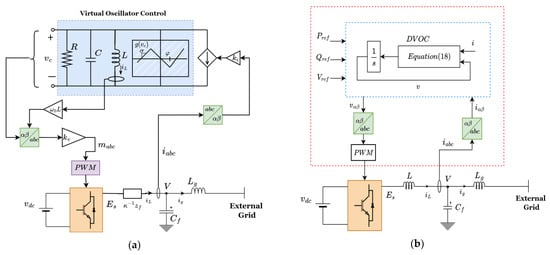
5. Virtual Oscillator Control (VOC)

The synchronisation ability of a network of coupled oscillators in a nonlinear dynamic network is used to implement the VOC model. Therefore, VOC utilises the dynamics of non-linear, weakly coupled oscillators to achieve a stable grid synchronisation mechanism in a limited-communication environment while regulating the voltage and frequency with proportional load-sharing capabilities [62][63][64][65].
VOC is a non-machine-emulating technique that does not require phasor measurements, or the calculation of quantities in a predefined synchronous state [66], but rather, achieves system-wise synchronisation stability of the local measurements in the underlying network in the real-time domain without direct communication. While loads may vary within a grid, VOC minimises any frequency deviations that threaten system stability and maintains the voltage with a droop capability in the steady state, a property that has been demonstrated in [67].
The basic VOC model, shown in Figure 3a, is built upon the dead zone oscillator, and is composed of the following features:
Figure 3. (a) Basic diagram of the virtual oscillator controller (VOC) [64]. (b) The dispatchable VOC (DVOC) model [68].
  • Parallel 𝐿𝐢 tank, which determines the resonant frequency that sets the system frequency.
  • 𝑔(𝑣𝑐) represents a voltage-dependent source. The value of its maximum slope, 𝜎, is related to the resistance, 𝑅, used for damping. The constant 𝜐 is the voltage scaling factor related to the grid RMS value, and πœ‘ and π‘˜π‘– are used to ensure that the voltage of the inverter is within the limits for safe supply to load. πœ… is related to the power rating of the GFM in proportion to other inverters within the network.
  • tank, which determines the resonant frequency that sets the system frequency.
  • 𝑔(𝑣𝑐)

represents a voltage-dependent source. The value of its maximum slope, 𝜎, is related to the resistance, 𝑅, used for damping. The constant 𝜐 is the voltage scaling factor related to the grid RMS value, and πœ‘ and π‘˜π‘– are used to ensure that the voltage of the inverter is within the limits for safe supply to load. πœ… is related to the power rating of the GFM in proportion to other inverters within the network.

Global synchronisation is based on the filter impedance, 𝑧𝑓, the effective impedance of the parallel 𝑅𝐿𝐢 branch in the oscillator, and the scaling factors π‘˜π‘£ and π‘˜π‘–.
A Van der Pol (VDP)-based VOC model was proposed in [69], designed using linear control methods to synthesise the required sinusoidal behaviour for application in AC power grids, with the capability for proportional power-sharing and droop characteristics in the steady state. The VDP-VOC structure deploys a current source with a cubic function of voltage obtained through 𝑔(𝑣𝑐)=𝛼(𝑣𝑐)3, while its general structure resembles that described for the basic VOC model, with 𝑅 replaced with a negative conductance element. The droop law embedded in the non-linearity of the VDP oscillator is shown through averaging methods in a slow timescale, and its stability in resistive networks is demonstrated through the global convergence of voltage in [70].
The nonlinearity of VOC laws leads to harmonics in the voltage output that require careful filter design to mitigate their effects. A modification of the cubic voltage function of the traditional VOC is addressed in [71], in which an improved VOC law was proposed to eliminate the third-order harmonic component in the voltage output, eliminating the need for notch filters, while making VOC faster in load response and synchronisation. A harmonic suppression method was proposed in [72]; using a virtual inductance control and current feedback from the network side of the output filter, compared to converter side current feedback in traditional methods, it led to simple implementation for grid-connected VOC inverters in the required performance region of passivity.
VDP-based VOC regulation of power flow in the grid-connected mode is constrained due to the lack of power control, and this issue was addressed in [73], in which a parameter was derived that describes voltage and power injection and could decouple real and active power; a controller was then designed to derive this parameter for different power references.
The dispatchable virtual oscillator control (dVOC) law was proposed in [74][75] to address the power control limitation of VOC-programmed inverters, while ensuring system-wide synchronisation.
The dVOC law [76] is as follows:
where 𝑣=[𝑣𝛼,𝑣𝛽]𝑇 is the terminal voltage in the π›Όπ›½βˆ’ frame, 𝑖=[𝑖𝛼,𝑖𝛽]𝑇 is the measured inverter current, πœ‚,𝛼>0 are positive constants, and 0<πœ…<πœ‹, 𝑅(πœ…)=[cosπœ…sinπœ…βˆ’sinπœ…cosπœ…], 𝐽=𝑅(πœ‹/2), 𝐾=1𝑉02𝑅(πœ…)[𝑃0βˆ’π‘„0𝑄0𝑃0], and πœ™(𝑣)=𝑉02βˆ’β€–π‘£β€–2𝑉02, where ‖𝑣‖ is the Euclidean norm. 𝑃0, 𝑄0, and 𝑉0 are the active power, reactive power, and voltage set points, respectively. πœ… caters for the line parameters, i.e., 0 for resistive and πœ‹2 for inductive lines. The dVOC controller is shown in Figure 13b.
By expressing 𝑣=[𝑣𝛼, 𝑣𝛽]𝑇 as 𝑣=‖𝑣‖ βˆ πœƒ, dVOC, the non-linear droop relationships are obtained as follows:
Assuming πœ…=πœ‹2 (for inductive impedance) and 𝑉0β‰ˆπ‘‰ for small voltage deviations in the steady state,

The authors of [76] tested the validity of the dVOC approach for inverters, showing its abilities for dynamic synchronisation, droop characteristics, black start, voltage regulation, and dynamic load sharing in an inverter-dominated grid.

A variant of the dVOC, proposed in [68], was based on the dynamics of the Andronov–Hopf oscillator (AHO), which is suitable for three-phase systems because of intrinsic orthogonal signal generation and performs better dynamically as compared to the traditional VOC, demonstrating better harmonic elimination. The controller is composed of an LC resonant tank of natural resonant frequency πœ”=1𝐿𝐢√ and nonlinear state-dependent voltage and current sources modelled after the nonlinear harmonic oscillators.
A benchmarking study on VOC oscillator implementations was carried out in [77], showing that the Andronov–Hopf-based dVOC is more suitable for grid applications, due to its superior dynamic and harmonic performance as compared to other implementations of VOC. A single-phase dVOC model, based on the VDP oscillator, was implemented in [78] to regulate power in a system of controlled and uncontrolled inverters, connected in parallel using tuneable proportional-integral (PI) controllers in the controlled inverters and proportional autonomous power sharing in the uncontrolled inverters, to supply a fixed load.
Nonlinear droop behaviour in frequency and voltage regulation was reported in [79] for the AHO-VOC inverter with decentralised and autonomous control for a system of interconnected inverters. The stability conditions for this nonlinear behaviour are addressed in [80], showing that nonlinear droop, also termed complex droop, presents better properties than conventional droop in the stable operation of the grid.
Despite VOC’s fast primary control, facilitated by instantaneous time-domain operation, it is difficult to incorporate into a hierarchical grid control, which is often required for both grid and island operation. The authors of [81] proposed a hierarchical secondary controller to facilitate the seamless transition of VOC in all modes of microgrid operation, with parameter regulation and synchronisation in island mode and power reference tracking in grid-tied modes.
VOC has been shown to operate in series-connected inverters in island mode, for which it offers decentralised synchronisation and control of inverters in a communication-free approach [82]. A port-Hamiltonian passivity-based VOC method for dealing with unknown grid conditions while ensuring synchronous stability was proposed in [83], satisfying a condition that is necessary for integration with systems of varied SCR values and disturbances.
Other limitations of VOC include inertia emulation for low-inertia systems, fault management, and fault ride-through capability in the grid-connected mode. Inertia emulation was proposed in [66], in which the power set point of dVOC was adjusted to enable the injection or absorption of power according to the differential power causing frequency deviation. Another implementation of the virtual inertia concept, using a proportional derivative controller approach to emulate inertia, was proposed in [84]. The fault ride-through capability of VOC was addressed in the unified virtual oscillator controller in [85], in which a fast overcurrent limiting mechanism was implemented. Current limiting is also proposed in a reduced dVOC model in [86] for overcurrent protection suitable for all grid impedances.
A system-level VOC control method was presented in [87]; termed sequence component-based VOC (S-VOC), it introduced improved control to encompass synchronisation of all sequence voltage components. This enabled VOC to deal with unbalanced voltages, integrating both single-phase and three-phase inverters, while accurately sharing power in hybrid structures with linear and nonlinear loads. This implementation was further improved in [88], in which S-VOC was combined with nested inner loops to decouple phases, improving the handling of unbalanced voltages with a feedback modification to the VOC that improved its unbalanced fault ride-through synchronous stability.

References

  1. Rosso, R.; Wang, X.; Liserre, M.; Lu, X.; Engelken, S. Grid-Forming Converters: Control Approaches, Grid-Synchronization, and Future Trendsβ€”A Review. IEEE Open J. Ind. Appl. 2021, 2, 93–109.
  2. Li, Z. Advanced Control of Grid-Forming Inverters under Uncertain Operating Conditions in AC Microgrids. Ph.D. Thesis, The Hong Kong Polytechnic University, Hongkong, China, 2021. Available online: https://theses.lib.polyu.edu.hk/handle/200/11693 (accessed on 17 July 2023).
  3. Dokus, M.; Mertens, A. On the Coupling of Power-Related and Inner Inverter Control Loops of Grid-Forming Converter Systems. IEEE Access 2021, 9, 16173–16192.
  4. Pereira, A.T.; Pinheiro, H. Inner Loop Controllers for Grid-Forming Converters. In Proceedings of the 2022 14th Seminar on Power Electronics and Control (SEPOC), Santa Maria, Brazil, 12–15 November 2022; pp. 1–6.
  5. Buso, S.; Caldognetto, T.; Liu, Q. Analysis and Experimental Characterization of a Large-Bandwidth Triple-Loop Controller for Grid-Tied Inverters. IEEE Trans. Power Electron. 2019, 34, 1936–1949.
  6. Gursoy, M.; Mirafzal, B. Direct vs. Indirect Control Schemes for Grid-Forming Inverters–Unveiling a Performance Comparison in a Microgrid. IEEE Access 2023, 11, 75023–75036.
  7. Pogaku, N.; Prodanovic, M.; Green, T.C. Modeling, Analysis and Testing of Autonomous Operation of an Inverter-Based Microgrid. IEEE Trans. Power Electron. 2007, 22, 613–625.
  8. Yazdani, A.; Iravani, R. Voltage-Sourced Converters in Power Systems: Modeling, Control, and Applications; Wiley: Hoboken, NJ, USA, 2010.
  9. Unruh, P.; Nuschke, M.; Strauß, P.; Welck, F. Overview on Grid-Forming Inverter Control Methods. Energies 2020, 13, 2589.
  10. Zhang, H.; Xiang, W.; Lin, W.; Wen, J. Grid Forming Converters in Renewable Energy Sources Dominated Power Grid: Control Strategy, Stability, Application, and Challenges. J. Mod. Power Syst. Clean Energy 2021, 9, 1239–1256.
  11. Abdel-Rahim, O.; Funato, H.; Junnosuke, H. Droop method based on model predictive control for DC microgrid. In Proceedings of the 2016 19th International Conference on Electrical Machines and Systems (ICEMS), Chiba, Japan, 13–16 November 2016; pp. 1–6.
  12. Majumder, R.; Ledwich, G.; Ghosh, A.; Chakrabarti, S.; Zare, F. Droop Control of Converter-Interfaced Microsources in Rural Distributed Generation. IEEE Trans. Power Deliv. 2010, 25, 2768–2778.
  13. D’Arco, S.; Suul, J.A. Virtual Synchronous Machinesβ€”Classification of Implementations and Analysis of Equivalence to Droop Controllers for Microgrids. In Proceedings of the 2013 IEEE Powertech Grenoble Conference, Grenoble, France, 16–20 June 2013; pp. 1–7.
  14. D’Arco, S.; Suul, J.A. Equivalence of Virtual Synchronous Machines and Frequency-Droops for Converter-Based MicroGrids. IEEE Trans. Smart Grid 2013, 5, 394–395.
  15. Sun, Y.; Hou, X.; Yang, J.; Han, H.; Su, M.; Guerrero, J.M. New Perspectives on Droop Control in AC Microgrid. IEEE Trans. Ind. Electron. 2017, 64, 5741–5745.
  16. Du, W.; Chen, Z.; Schneider, K.P.; Lasseter, R.H.; Nandanoori, S.P.; Tuffner, F.K.; Kundu, S. A Comparative Study of Two Widely Used Grid-Forming Droop Controls on Microgrid Small-Signal Stability. IEEE J. Emerg. Sel. Top. Power Electron. 2020, 8, 963–975.
  17. Shi, Y.; Gu, X.; Yin, X.; Feng, S.; Zhang, S. Design of droop controller in islanded microgrids using multi-objective optimisation based on accurate small-signal model. IET Power Electron. 2022, 15, 1093–1109.
  18. Eberlein, S.; Rudion, K. Small-signal stability modelling, sensitivity analysis and optimization of droop controlled inverters in LV microgrids. Int. J. Electr. Power Energy Syst. 2021, 125, 106404.
  19. Eberlein, S.; Rudion, K. Optimisation, benchmark testing and comparison of droop control variants in microgrids. IET Smart Grid 2021, 4, 536–548.
  20. Belal, E.K.; Yehia, D.M.; Azmy, A.M. Effective Power Management of DC Microgrids Using Adaptive Droop Control. In Proceedings of the 2018 Twentieth International Middle East Power Systems Conference (MEPCON), Cairo, Egypt, 18–20 December 2018; pp. 905–910.
  21. Gurugubelli, V.; Ghosh, A.; Panda, A.K.; Rudra, S. Implementation and comparison of droop control, virtual synchronous machine, and virtual oscillator control for parallel inverters in standalone microgrid. Int. Trans. Electr. Energy Syst. 2021, 31, e12859.
  22. Zhang, L.; Harnefors, L.; Nee, H.-P. Power-Synchronization Control of Grid-Connected Voltage-Source Converters. IEEE Trans. Power Syst. 2010, 25, 809–820.
  23. Ahmed, H.Y.; Abdel-Rahim, O.; Ali, Z.M. New High-Gain Transformerless DC/DC Boost Converter System. Electronics 2022, 11, 734.
  24. Zhang, L.; Harnefors, L.; Nee, H.-P. Interconnection of Two Very Weak AC Systems by VSC-HVDC Links Using Power-Synchronization Control. IEEE Trans. Power Syst. 2011, 26, 344–355.
  25. Sepehr, A.; Gomis-Bellmunt, O.; Pouresmaeil, E. Employing Machine Learning for Enhancing Transient Stability of Power Synchronization Control During Fault Conditions in Weak Grids. IEEE Trans. Smart Grid 2022, 13, 2121–2131.
  26. Zhang, L.; Nee, H.-P.; Harnefors, L. Analysis of Stability Limitations of a VSC-HVDC Link Using Power-Synchronization Control. IEEE Trans. Power Syst. 2011, 26, 1326–1337.
  27. Harnefors, L.; Hinkkanen, M.; Riaz, U.; Rahman, F.M.M.; Zhang, L. Robust Analytic Design of Power-Synchronization Control. IEEE Trans. Ind. Electron. 2019, 66, 5810–5819.
  28. Xiong, X.; Zhou, Y.; Luo, B.; Cheng, P.; Blaabjerg, F. Analysis and Suppression Strategy of Synchronous Frequency Resonance for Grid-Connected Converters with Power-Synchronous Control Method. IEEE Trans. Power Electron. 2023, 38, 6945–6955.
  29. Wu, H.; Wang, X. Design-Oriented Transient Stability Analysis of Grid-Connected Converters with Power Synchronization Control. IEEE Trans. Ind. Electron. 2019, 66, 6473–6482.
  30. Yazdani, S.; Davari, M.; Ferdowsi, M.; Shamsi, P. Internal Model Power Synchronization Control of a PV-Based Voltage-Source Converter in Weak-Grid and Islanded Conditions. IEEE Trans. Sustain. Energy 2021, 12, 1360–1371.
  31. Yazdani, S.; Ferdowsi, M.; Shamsi, P. Power Synchronization PID Control Method for Grid-Connected Voltage-Source Converters. In Proceedings of the 2020 IEEE Kansas Power and Energy Conference (KPEC), Manhattan, KS, USA, 13–14 July 2020; pp. 1–6.
  32. Driesen, J.; Visscher, K. Virtual synchronous generators. In Proceedings of the 2008 IEEE Power and Energy Society General Meeting Conversion and Delivery of Electrical Energy in the 21st Century, Pittsburgh, PA, USA, 20–24 July 2008; pp. 1–3.
  33. Liu, J.; Miura, Y.; Bevrani, H.; Ise, T. Enhanced Virtual Synchronous Generator Control for Parallel Inverters in Microgrids. IEEE Trans. Smart Grid 2017, 8, 2268–2277.
  34. Li, B.; Zhou, L.; Yu, X.; Zheng, C.; Liu, J. Improved power decoupling control strategy based on virtual synchronous generator. IET Power Electron. 2017, 10, 462–470.
  35. Shuai, Z.; Shen, C.; Liu, X.; Li, Z.; Shen, Z.J. Transient Angle Stability of Virtual Synchronous Generators Using Lyapunov’s Direct Method. IEEE Trans. Smart Grid 2019, 10, 4648–4661.
  36. Chen, M.; Zhou, D.; Blaabjerg, F. Enhanced Transient Angle Stability Control of Grid-Forming Converter Based on Virtual Synchronous Generator. IEEE Trans. Ind. Electron. 2022, 69, 9133–9144.
  37. Xiong, X.; Wu, C.; Hu, B.; Pan, D.; Blaabjerg, F. Transient Damping Method for Improving the Synchronization Stability of Virtual Synchronous Generators. IEEE Trans. Power Electron. 2021, 36, 7820–7831.
  38. Sadeque, F.; Fateh, F. On Control Schemes for Grid-Forming Inverters. In Proceedings of the 2022 IEEE Kansas Power and Energy Conference (KPEC), Manhattan, KS, USA, 25–26 April 2022; pp. 1–6.
  39. Shintai, T.; Miura, Y.; Ise, T. Oscillation Damping of a Distributed Generator Using a Virtual Synchronous Generator. IEEE Trans. Power Deliv. 2014, 29, 668–676.
  40. Wang, L.; Zhou, H.; Hu, X.; Hou, X.; Su, C.; Sun, K. Adaptive Inertia and Damping Coordination (AIDC) Control for Grid-Forming VSG to Improve Transient Stability. Electronics 2023, 12, 2060.
  41. Cheema, K.M.; Chaudhary, N.I.; Tahir, M.F.; Mehmood, K.; Mudassir, M.; Kamran, M.; Milyani, A.H.; Elbarbary, Z.S. Virtual synchronous generator: Modifications, stability assessment and future applications. Energy Rep. 2022, 8, 1704–1717.
  42. Li, J.; Li, Y.; Du, Z.; Xu, Z.; Dong, Z. Damping Turning Rule of Virtual Synchronous Generator for Global Stability. IEEE Trans. Power Deliv. 2023, 38, 2650–2660.
  43. Li, C.; Yang, Y.; Cao, Y.; Wang, L.; Blaabjerg, F.; Dragicevic, T. Frequency and Voltage Stability Analysis of Grid-Forming Virtual Synchronous Generator Attached to Weak Grid. IEEE J. Emerg. Sel. Top. Power Electron. 2022, 10, 2662–2671.
  44. Chen, S.; Sun, Y.; Han, H.; Fu, S.; Luo, S.; Shi, G. A Modified VSG Control Scheme with Virtual Resistance to Enhance Both Small-Signal Stability and Transient Synchronization Stability. IEEE Trans. Power Electron. 2023, 38, 6005–6014.
  45. Miranbeigi, M.; Kandula, P.; Divan, D. A New Representation based on Virtual Capacitor for Virtual Synchronous Generators. In Proceedings of the 2020 IEEE 11th International Symposium on Power Electronics for Distributed Generation Systems (PEDG), Dubrovnik, Croatia, 28 September–1 October 2020; pp. 205–210.
  46. Suvorov, A.; Askarov, A.; Bay, Y.; Maliuta, B.; Achitaev, A.; Suslov, K. Comparative small-signal stability analysis of voltage-controlled and enhanced current-controlled virtual synchronous generators under weak and stiff grid conditions. Int. J. Electr. Power Energy Syst. 2023, 147, 108891.
  47. Yang, Y.; Xu, J.; Li, C.; Zhang, W.; Wu, Q.; Wen, M.; Blaabjerg, F. A New Virtual Inductance Control Method for Frequency Stabilization of Grid-Forming Virtual Synchronous Generators. IEEE Trans. Ind. Electron. 2023, 70, 441–451.
  48. Lu, S.; Zhu, Y.; Dong, L.; Na, G.; Hao, Y.; Zhang, G.; Zhang, W.; Cheng, S.; Yang, J.; Sui, Y. Small-Signal Stability Research of Grid-Connected Virtual Synchronous Generators. Energies 2022, 15, 7158.
  49. Zhong, Q.-C.; Weiss, G. Synchronverters: Inverters that mimic synchronous generators. IEEE Trans. Ind. Electron. 2011, 58, 1259–1267.
  50. Tayyebi, A.; DΓΆrfler, F.; Kupzog, F.; Miletic, Z.; Hribernik, W. Grid-Forming Convertersβ€”Inevitability, Control Strategies and Challenges in Future Grids Application. In Proceedings of the CIRED 2018 Ljubljana Workshop, Ljubljana, Slovenia, 7–8 June 2018.
  51. Rosso, R.; Engelken, S.; Liserre, M. A Generalized Formulation of Active Power Synchronization Based Control Algorithms for Grid Connected Converters. In Proceedings of the IECON 2018β€”44th Annual Conference of the IEEE Industrial Electronics Society, Washington, DC, USA, 21–23 October 2018; pp. 883–888.
  52. Zhong, Q.-C.; Nguyen, P.-L.; Ma, Z.; Sheng, W. Self-Synchronized Synchronverters: Inverters Without a Dedicated Synchronization Unit. IEEE Trans. Power Electron. 2014, 29, 617–630.
  53. Natarajan, V.; Weiss, G. Synchronverters with Better Stability Due to Virtual Inductors, Virtual Capacitors, and Anti-Windup. IEEE Trans. Ind. Electron. 2017, 64, 5994–6004.
  54. Lorenzetti, P.; Kustanovich, Z.; Shivratri, S.; Weiss, G. The Equilibrium Points and Stability of Grid-Connected Synchronverters. IEEE Trans. Power Syst. 2022, 37, 1184–1197.
  55. Vasudevan, K.R.; Ramachandaramurthy, V.K.; Babu, T.S.; Pouryekta, A. Synchronverter: A Comprehensive Review of Modifications, Stability Assessment, Applications and Future Perspectives. IEEE Access 2020, 8, 131565–131589.
  56. Gomes, L.D.N.; Abrantes-Ferreira, A.J.G.; Dias, R.F.d.S.; Rolim, L.G.B. Synchronverter-Based STATCOM With Voltage Imbalance Compensation Functionality. IEEE Trans. Ind. Electron. 2022, 69, 4836–4844.
  57. Remon, D.; Cantarellas, A.M.; Rakhshani, E.; Candela, I.; Rodriguez, P. An active power synchronization control loop for grid-connected converters. In Proceedings of the IEEE Power & Energy Society General Meeting, National Harbor, MD, USA, 27–31 July 2014; IEEE: Piscataway, NJ, USA, 2014; pp. 1–5.
  58. Arghir, C.; Jouini, T.; DΓΆrfler, F. Grid-forming control for power converters based on matching of synchronous machines. Automatica 2018, 95, 273–282.
  59. Curi, S.; Gross, D.; Dorfler, F. Control of low-inertia power grids: A model reduction approach. In Proceedings of the 2017 IEEE 56th Annual Conference on Decision and Control (CDC), Melbourne, VIC, Australia, 12–15 December 2017; pp. 5708–5713.
  60. Jouini, T.; Arghir, C.; DΓΆrfler, F. Grid-Friendly Matching of Synchronous Machines by Tapping into the DC Storage. IFAC-Pap. Online 2016, 49, 192–197.
  61. Arghir, C.; Dorfler, F. The Electronic Realization of Synchronous Machines: Model Matching, Angle Tracking, and Energy Shaping Techniques. IEEE Trans. Power Electron. 2020, 35, 4398–4410.
  62. DΓΆrfler, F.; Chertkov, M.; Bullo, F. Synchronization in complex oscillator networks and smart grids. Proc. Natl. Acad. Sci. USA 2013, 110, 2005–2010.
  63. Torres, L.A.B.; Hespanha, J.P.; Moehlis, J. Synchronization of Identical Oscillators Coupled Through a Symmetric Network with Dynamics: A Constructive Approach with Applications to Parallel Operation of Inverters. IEEE Trans. Autom. Control 2015, 60, 3226–3241.
  64. Johnson, B.B.; Dhople, S.V.; Hamadeh, A.O.; Krein, P.T. Synchronization of Parallel Single-Phase Inverters with Virtual Oscillator Control. IEEE Trans. Power Electron. 2014, 29, 6124–6138.
  65. Dhople, S.V.; Johnson, B.B.; Hamadeh, A.O. Virtual Oscillator Control for voltage source inverters. In Proceedings of the 2013 51st Annual Allerton Conference on Communication, Control, and Computing (Allerton), Monticello, IL, USA, 2–4 October 2013; pp. 1359–1363.
  66. Aghdam, S.A.; Agamy, M. Virtual oscillator-based methods for grid-forming inverter control: A review. IET Renew. Power Gener. 2022, 16, 835–855.
  67. Sinha, M.; Dorfler, F.; Johnson, B.B.; Dhople, S.V. Virtual Oscillator Control subsumes droop control. In Proceedings of the 2015 American Control Conference (ACC), Chicago, IL, USA, 1–3 July 2015; pp. 2353–2358.
  68. Lu, M.; Dutta, S.; Purba, V.; Dhople, S.; Johnson, B. A Grid-compatible Virtual Oscillator Controller: Analysis and Design. In Proceedings of the 2019 IEEE Energy Conversion Congress and Exposition (ECCE), Baltimore, MD, USA, 29 September–3 October 2019; pp. 2643–2649.
  69. Johnson, B.B.; Sinha, M.; Ainsworth, N.G.; Dorfler, F.; Dhople, S.V. Synthesizing Virtual Oscillators to Control Islanded Inverters. IEEE Trans. Power Electron. 2016, 31, 6002–6015.
  70. Sinha, M.; Dorfler, F.; Johnson, B.B.; Dhople, S.V. Uncovering Droop Control Laws Embedded Within the Nonlinear Dynamics of Van der Pol Oscillators. IEEE Trans. Control Netw. Syst. 2017, 4, 347–358.
  71. Luo, S.; Wu, W.; Koutroulis, E.G.; Chung, H.S.-H.; Blaabjerg, F.G. A New Virtual Oscillator Control Without Third-Harmonics Injection For DC/AC Inverter. IEEE Trans. Power Electron. 2021, 36, 10879–10888.
  72. Awal, M.A.; Yu, H.; Husain, I.; Yu, W.; Lukic, S.M. Selective Harmonic Current Rejection for Virtual Oscillator Controlled Grid-Forming Voltage Source Converters. IEEE Trans. Power Electron. 2020, 35, 8805–8818.
  73. Raisz, D.; Thai, T.T.; Monti, A. Power Control of Virtual Oscillator Controlled Inverters in Grid-Connected Mode. IEEE Trans. Power Electron. 2019, 34, 5916–5926.
  74. Colombino, M.; Gros, D.; Dorfler, F. Global phase and voltage synchronization for power inverters: A decentralized consensus-inspired approach. In Proceedings of the 2017 IEEE 56th Annual Conference on Decision and Control (CDC), Melbourne, VIC, Australia, 12–15 December 2017; pp. 5690–5695.
  75. Colombino, M.; Groz, D.; Brouillon, J.-S.; Dorfler, F. Global Phase and Magnitude Synchronization of Coupled Oscillators with Application to the Control of Grid-Forming Power Inverters. IEEE Trans. Autom. Control 2019, 64, 4496–4511.
  76. Seo, G.-S.; Colombino, M.; Subotic, I.; Johnson, B.; Gros, D.; Dorfler, F. Dispatchable Virtual Oscillator Control for Decentralized Inverter-dominated Power Systems: Analysis and Experiments. In Proceedings of the 2019 IEEE Applied Power Electronics Conference and Exposition (APEC), Anaheim, CA, USA, 17–21 March 2019; pp. 561–566.
  77. Lu, M.; Dhople, S.V.; Johnson, B. Benchmarking Nonlinear Oscillators for Grid-Forming Inverter Control. IEEE Trans. Power Electron. 2022, 37, 10250–10266.
  78. Ali, M.; Nurdin, H.I.; Fletcher, J.E. Dispatchable Virtual Oscillator Control for Single-Phase Islanded Inverters: Analysis and Experiments. IEEE Trans. Ind. Electron. 2021, 68, 4812–4826.
  79. Lu, M. Virtual Oscillator Grid-Forming Inverters: State of the Art, Modeling, and Stability. IEEE Trans. Power Electron. 2022, 37, 11579–11591.
  80. He, X.; Haberle, V.; Subotic, I.; Dorfler, F. Nonlinear Stability of Complex Droop Control in Converter-Based Power Systems. IEEE Control Syst. Lett. 2023, 7, 1327–1332.
  81. Awal, M.A.; Yu, H.; Tu, H.; Lukic, S.M.; Husain, I. Hierarchical Control for Virtual Oscillator Based Grid-Connected and Islanded Microgrids. IEEE Trans. Power Electron. 2020, 35, 988–1001.
  82. Lu, M.; Dutta, S.; Johnson, B. Self-Synchronizing Cascaded Inverters with Virtual Oscillator Control. IEEE Trans. Power Electron. 2022, 37, 6424–6436.
  83. Kong, L.; Xue, Y.; Qiao, L.; Wang, F. Enhanced Synchronization Stability of Grid-Forming Inverters with Passivity-Based Virtual Oscillator Control. IEEE Trans. Power Electron. 2022, 37, 14141–14156.
  84. Li, J.; Fletcher, J.E.; Holmes, D.; McGrath, B. Developing a machine equivalent inertial response for a Virtual Oscillator Controlled Inverter in a machine-inverter based microgrid. In Proceedings of the 2020 IEEE Energy Conversion Congress and Exposition (ECCE), Detroit, MI, USA, 11–15 October 2020; pp. 4314–4321.
  85. Awal, M.A.; Husain, I. Unified Virtual Oscillator Control for Grid-Forming and Grid-Following Converters. IEEE J. Emerg. Sel. Top. Power Electron. 2021, 9, 4573–4586.
  86. Ajala, O.; Lu, M.; Johnson, B.B.; Dhople, S.V.; Dominguez-Garcia, A. Model Reduction for Inverters with Current Limiting and Dispatchable Virtual Oscillator Control. IEEE Trans. Energy Convers. 2022, 37, 2250–2259.
  87. Ghosh, R.; Tummuru, N.R.; Rajpurohit, B.S. Modified VOC Using Three Symmetrical Components for Grid-Supporting Operation During Unbalanced Grid Voltages and Grid-Forming Operation in Hybrid Single-Phase/Three-Phase Microgrid. IEEE Trans. Ind. Electron. 2023, 70, 11276–11286.
  88. Ghosh, R.; Tummuru, N.R.; Rajpurohit, B.S. A New Virtual Oscillator-Based Grid-Forming Controller with Decoupled Control Over Individual Phases and Improved Performance of Unbalanced Fault Ride-Through. IEEE Trans. Ind. Electron. 2023, 70, 12465–12474.
More
Video Production Service