Your browser does not fully support modern features. Please upgrade for a smoother experience.
Please note this is a comparison between Version 1 by Nannan Wang and Version 2 by Sirius Huang.
Ultrasound waves have been widely used in the field of organic wastewater treatment due to their mechanical, thermal, and chemical effects derived from their cavitation effect. Many researchers have combined ultrasound waves with other organic wastewater treatment methods because they have the potential to offset the disadvantages of other method.
- cavitation mechanism
- ultrasound operation mode
- ultrasound reactor
- organic wastewater treatment
- physical fields
1. Introduction
Environmental pollution has become a concern worldwide, because it seriously hinders the sustainable development of our world [1]. Organic wastewater is one of the main pollution sources because of toxic refractory organic pollutants in wastewater, which can be enriched in the human body and animals through the food chain; this seriously endangers human health and natural ecology [2]. The main types of organic wastewater include dye wastewater, pharmaceutical wastewater, coking wastewater, atrazine wastewater, high saline petrochemical wastewater, dairy wastewater, etc. [3][4][5][6][7][8][9][10][11][12][3,4,5,6,7,8,9,10,11,12]. In order to effectively eliminate organic pollutants in wastewater, many methods have been explored, and they can be divided into a chemical oxidation degradation process [13], biochemical degradation process [14], and physicochemical degradation process. However, every method has shortcomings [15]. Against this backdrop, some physical fields such as an ultrasound field, MW field, and UV/visible light field were introduced to compensate for these shortcomings, thus enhancing the treatment efficiency of wastewater.
In these physical fields, the ultrasound field is different from other physical fields because it belongs to a mechanical field, while other physical fields belong to the electromagnetic field; ultrasound works by relying on high-frequency vibrations and a subsequent cavitation effect [16]. According to the definition from the American National Standards Institute, ultrasound is a type of dense longitudinal wave with a frequency of >20 kHz; it can be generated by a piezoelectric effect (generated by the interaction of mechanical pressure and electricity) or magnetostriction (generated in electromagnetic fields) [17]. Ultrasound can transmit strong energy and produce a considerable impact between interfaces when it is propagated in a gas, liquid, or solid, accompanied with the consumption of energy and the corrosion of equipment and materials [18][19][18,19]. As the application of ultrasound in the treatment of organic wastewater does not involve the addition of chemicals and does not cause secondary pollution [20], ultrasound is welcomed by many researchers, and it has been applied in combination with other treatment methods such as electrochemistry oxidation, photocatalytic oxidation, FE oxidation, membrane filtration, and PS oxidation [21]; its excellent enhancement capacity to various treatment methods of organic wastewater has been confirmed by many reports [22][23][24][22,23,24].
2. Typical Ultrasound-Enhanced Organic Wastewater Treatment Equipment
2.1. Classification by Reactor Type
2.1.1. Ultrasound Cleaning Tank-Type Reactor
Ultrasound cleaning tank-type reactors are usually equipped with transducers on both sides (No. 7 in Figure 13a) or at the bottom of the reactor (No. 4 in Figure 13b). The advantage of the installation position of the transducer is that the transducer can be controlled easily to adjust the output power, and corrosion of the transducer can be avoided [25][94].
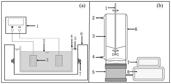
Figure 13. Device diagram of (a) ultrasound cleaning tank reactor and (b) ultrasound amplifier coupled transducer [4][26][4,67]. ((a) 1. Power supply, 2. wastewater, 3. electrode, 4. Perspex vessel, 5. water (20 °C), 6. ultrasound generation, 7. ultrasound transducer. (b) 1. Stirrer, 2. cooling water outlet, 3. cylindrical glass reactor, 4. cooling water inlet, 5. ultrasound transducer, 6. cooling jacket, 7. ultrasound amplifier and frequency controller, 8. ultrasound power supply).
As shown in Figure 13a, the temperature of the cooling water (No. 5) in the cleaning tank can be adjusted to control the temperature of the wastewater in Perspex vessel (No. 4) to achieve the optimal treatment temperature. In addition, researchers can achieve the optimal frequency and power of ultrasound by adjusting the transducer. Yang et al. removed more than 94.0% of COD from cephalosporin pharmaceutical wastewater by using this experimental device [4].
As shown in Figure 13b, ultrasound with a frequency of 3.82–140 kHz can be generated by a disk transducer (No. 5) at the bottom of the glass reactor (No. 3) [27][29]. The reactor is surrounded by a cooling jacket (No. 6) to achieve the required treatment temperature. This kind of device can easily output high-frequency ultrasound to effectively realize cavitation conditions. Bremner et al. [26][67] obtained a 29.0% removal rate of TOC in the aqueous phenol solutions by using the device in Figure 13b.
2.1.2. Ultrasound Probe Reactor
As shown in Figure 24, the probe transducer (No. 2) is the most important part of the reactor. The maximum transmission coefficient of ultrasound takes place along the axial direction of the probe and drops sharply in the radial direction of the probe. In addition, the emission power of the probe is adjustable. As the small diameter of the probe limits its effective working range, the use of this kind of reactor has been limited to the laboratory stage until now [28][71].
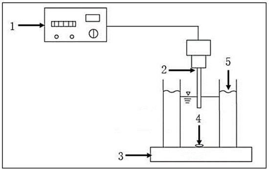
It is noteworthy that this kind of reactor is convenient to use, but the probe immersed in the solution can be eroded easily using the mechanical effect of ultrasound, and the vibration from the probe will raise the temperature of the solution and affect its service life. Thus, low-temperature liquid should be circulated in the jacket when necessary [25][94].
The treatment efficiency of organic wastewater in such a kind of reactor cannot satisfy people’s requirements. However, ultrasound can play an excellent auxiliary role and promote the efficiency of organic degradation when combined with other methods. Peng et al. [29][95] reported that only 4.0% of polycyclic aromatic hydrocarbons were degraded by ultrasound alone in 120 min, while the degradation rate reached 84.8% in the ultrasound-PS process. In addition, in the treatment of carbofuran [30][73], the removal efficiency of carbofuran (99.0%) in the ultrasound–FE process was much higher than that (60.0%) in the ultrasound alone system.
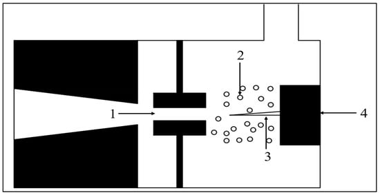
The above two types of reactors are the mainstream reactors at present, whereas the liquid whistle reactor is not common now. Unlike transducers, ultrasound in the liquid whistle reactor is generated by the jet impinging on the metal blade (No. 3, Figure 35). The sound intensity in the reactor can be adjusted by changing the shape of the jet. In addition, ultrasound frequency can be adjusted by the flow rate. This kind of reactor is always used in the emulsification and homogenization of oily wastewater [31][96].
2.1.3. Comparison of Ultrasound Reactors with Different Types
Table 1 compares the advantages and disadvantages of three types of ultrasound reactors. Firstly, the cleaning tank reactor has a wide range of uses and can be used to clean experimental equipment. It is relatively common to simply place the reaction tank in the cleaning tank during the reaction, and the external water bath can also control the temperature, but this also limits the size of the reaction tank. Subsequently, the ultrasound probe-type reactor only needs to insert the probe into the reaction solution during reaction, which is easy to operate. However, the ultrasound distribution is uneven, and the probe is prone to corrosion after long-term use. Finally, liquid whistle-type reactors are uncommon now, which are used for the averaging and emulsification of oily wastewater.
Table 1.
Comparison of different types of reactors.
| Reactors | Advantages | Disadvantages |
| Ultrasound cleaning tank-type reactor | Ultrasound wave is evenly distributed; Can easily control temperature. |
Limiting the reactor size. |
| Ultrasound probe reactor | Uneven distribution of ultrasound wave; The probe is prone to corrosion. |
Easy operation. |
| Liquid whistle reactor | Application in homogenization of oily wastewater. | Ancient, with certain limitations. |
2.2. Classified According to Liquid Flow Mode
2.2.1. Fully Mixed Reactor
The ultrasound cleaning tank-type reactor and ultrasound probe reactor can both work in fully mixed mode. The fully mixed reactor can be used in various ultrasound processes, including ultrasound alone, the ultrasound–PS process, the ultrasound–FE process, the ultrasound–electrochemistry process, the ultrasound–photocatalytic oxidation process, etc.
When ultrasound works alone or works with PS or a Fenton-like process, the reaction can be easily started by adding PS or Fe2+/H2O2 to the system. However, in the ultrasound–electrochemistry process (Figure 46a) the addition of an anode and cathode at both sides of the reactor (No. 3 and 5) is necessary. In addition, particle electrode may be needed as well if the fully mixed reactor can play the role of a three-dimensional electrode system. When the fully mixed reactor works with the photocatalytic oxidation process, UV lamp (No. 3, Figure 46b) or other light sources and a photocatalyst are needed.
The fully mixed reactor is generally equipped with a mechanical stirrer to evenly mix the wastewater and chemical reagents [32][97]. If the temperature and pH need to be controlled, a temperature controller and pH sensor will be set, respectively. The wastewater in the fully mixed reactor can be easily mixed uniformly. However, the capacity of the fully mixed reactor is limited, and it cannot work in a continuous mode. The treatment efficiency of organic wastewater in such a kind of reactor is very high, for example, the decolorization rate of reactive black 5 dye treated by the reactor, outlined in Figure 46a, reached 89.0% [33][45], while 99.9% rhodamine 6G and 88.7% phenol were removed by the reactor, as outlined in Figure 46b [34][98].
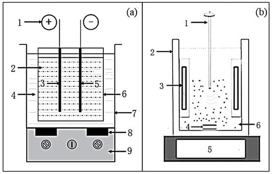
Figure 46. Experimental device of (a) ultrasound−EC process, and (b) continuous stirred tank of ultrasound−UV process [33][34][45,98]. ((a) 1. DC power supply, 2. dye solution, 3. anode, 4. distilled water, 5. cathode, 6. glass reactor, 7. ultrasound bath, 8. transducer, 9. ultrasound control unit. (b) 1. Ultrasound probe, 2. cooling water jacket, 3. UV lamp, 4. magnetic bar, 5. magnetic stirrer, 6. dye solution).
2.2.2. Continuous Reactor
In the continuous reactor, the ultrasound unit always works with other organic wastewater treatment units, and common treatment processes include, but are not limited to, the ultrasound–O3 process (Figure 57a), the ultrasound–MW process (Figure 57b), the ultrasound–membrane process (Figure 57c), etc.
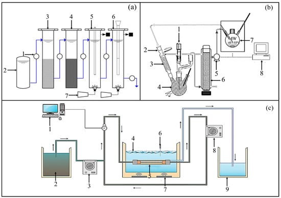
Figure 57. Experimental device diagram of (a) push flow reactor of ultrasound–UV–O3 process, (b) ultrasound–MW process, (c) ultrasound-membrane process [35][36][37][50,61,92]. ((a) 1. Pump, 2. storage tank, 3. coarse sand, 4. fine sand, 5. UV unit, 6. ultrasound unit, 7. O3 generators. (b) 1. Inlet, 2. cooling water outlet, 3. intensive condenser, 4. outlet and sampler, 5. pump, 6. ultrasound generator, 7. MW generator, 8. control center. (c) 1. Pressure meter and transducer, 2. feed tank, 3. peristaltic pump, 4. ice, 5. membrane module, 6. ultrasound bath, 7. temperature probe, 8. peristaltic pump, 9. permeate tank).
As for the ultrasound–O3 process, the organic wastewater is first filtered by coarse sand (No. 3) and fine sand (No. 4) and then sequentially entered into the UV unit (No. 5) and the ultrasound unit (No. 6). After the treatment, the treated organic wastewater can be discharged. Both of the bottoms of the UV unit and ultrasound unit are equipped with O3 generators (No. 7). They can determine the optimal scheme to adjust the experimental scheme. Using this device, 97.7% of atrazine was degraded in the study of Jing et al. [35][50].
As for the ultrasound–MW process, the function of MW is to control temperature. After the ultrasound treatment (No. 6), organic wastewater enters the circulation system for cooling. A control center is usually set (No. 8) to control the flow, temperature, and MW power. Using this device, up to 76.0% of phenol was degraded in the study of Wu et al. [36][61], which is equivalent to the sum of the degradation achieved by the separate treatment of ultrasound and MW.
As for the ultrasound–membrane process, the membrane module (No. 5) is usually immersed in the ultrasound bath (No. 6), and then the wastewater is pumped into the ultrasound bath and flows out after the ultrasound treatment and membrane filtration. The continuous reactor is suitable for the tandem treatment of wastewater by sequentially passing the treatment units. The disadvantage is that the reactor design is complex, and the operation cost is high.
2.2.3. Comparison of Ultrasound Reactors with Different Flow Modes
Table 2 is a comparative table of advantages and disadvantages classified by flow mode. For a fully mixed flow reactor, the reaction solution can be completely mixed and fully reacted, and the operation is simple, but it can only be reacted in batches. For continuous flow reactors, the solution can be continuously treated, but different types of treatment methods require redesigning the reactor, which is costly.
Table 2.
Comparison of reactors with different flow modes.
| Types | Advantages | Disadvantages |
|---|---|---|
| Fully mixed reactor | Mix the solution evenly. Convenient combination with other processing methods. | Unable to process continuously. |
| Continuous reactor | Continuous processing. | Complex design and high cost. |