The foot and ankle serve vital roles in weight bearing, balance, and flexibility but are susceptible to many diverse ailments, making treatment difficult. More commonly, Total Ankle Arthroplasty (TAA) and Total Talus Replacement (TTR) are used for patients with ankle degeneration and avascular necrosis of the talus, respectively. Ankle prosthesis and orthosis are also indicated for use with lower limb extremity amputations or locomotor disability, leading to the development of powered exoskeletons. However, patient outcomes remain suboptimal, commonly due to the misfitting of implants to the patient-specific anatomy. Additive manufacturing (AM) is being used to create customized, patient-specific implants and porous implant cages that provide structural support while allowing for increased bony ingrowth and to develop customized, lightweight exoskeletons with multifunctional actuators. AM implants and devices have shown success in preserving stability and mobility of the joint and achieving fast recovery, as well as significant improvements in gait rehabilitation, gait assistance, and strength for patients.
1. Introduction
The foot and ankle form a complex system of 28 bones and 33 joints and are involved in a wide variety of vital functions, including weight bearing, balance, shock absorption, and flexibility to ground terrain. The foot and ankle are common sites of emergent injury; for instance, ankle fractures account for over 20% of visits to the emergency room due to lower extremity fractures
[1]. Injuries and ailments that affect the foot and ankle have been attributed to a wide variety of causes, ranging from high-energy trauma to end-stage osteoarthritis, making treatment of the injury difficult. Damage to the foot and ankle can be debilitating, causing pain and loss of function in bearing weight and walking for the patient. In recent years, it has been reported that the direct cost of managing ankle/foot fracture can reach up to almost USD 22,000/patient, while treatment of soft tissue injury averages around USD 2700/patient
[2]. Long-term recovery prognosis is also reported as variable and suboptimal in the literature
[3].
Prosthetic components have become increasingly popular, ranging from single bone/joint components to functional limb prosthetics. Accordingly, attention in the scientific community has been paid to improving foot and ankle prosthetic options. With discomfort due to improper fit being the most common cause of rejection of prosthetic devices
[4], it is vital to produce dependable prosthetic devices for patients
[5]. Additive manufacturing (AM), or the industrial process for three-dimensional (3D) printing, has become increasingly prevalent in the development of custom prosthetic devices for individual patients, thereby improving patient satisfaction.
2. Total Ankle Replacement
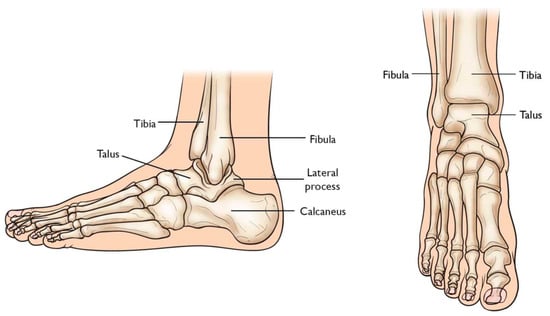
Total Ankle Arthroplasty (TAA) is an orthopedic procedure used as an increasingly popular treatment for patients with end-stage arthritis in the ankle joint. The ankle joint, also known as the tibiotalar joint, is formed from the meeting of the tibia, fibula, and talus bone
[6][18], shown and labeled in
Figure 12. Wearing of the cartilage within the joint can lead to the bone ends rubbing against each other, causing bone spurs, inflammation, stiffness, osteophyte formation, and pain in the joint, overall resulting in severely decreased function
[6][7][18,19].
Figure 12. Graphic of bones in ankle joint, including talus, fibula, tibia, calcaneus, and surrounding bones [8]. Graphic of bones in ankle joint, including talus, fibula, tibia, calcaneus, and surrounding bones [20].
2.1. The Evolution of Total Ankle Arthroplasty Implants
Previously, ankle arthrodesis (AA), which consists of fusing two or more bones within the joint together, was considered the standard treatment for end-stage ankle arthritis
[9][21]. While studies have reported patient satisfaction following AA as very high, assessment of functional outcomes has shown reduced mobility of the joint during activities of daily living as well as post-surgical degeneration of the neighboring subtalar joint
[9][10][11][12][13][21,22,23,24,25].
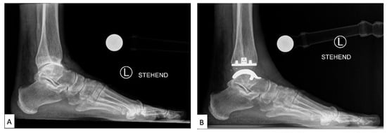
TAA was developed as a method of reducing pain while also preserving the mobility of the joint. Early first-generation TAA implants (
Figure 23) consisted of two components: a concave tibial component composed of polyethylene and a convex talar component composed of metal alloy, both fixated with bone cement. However, early TAA implants are still associated with a high rate of failure, which has been attributed to permanent deformation of the polyethylene component, large bone resection to allow for cement fixation and loosening of the talar component due to the high strength of the talus bone
[9][11][12][13][21,23,24,25].
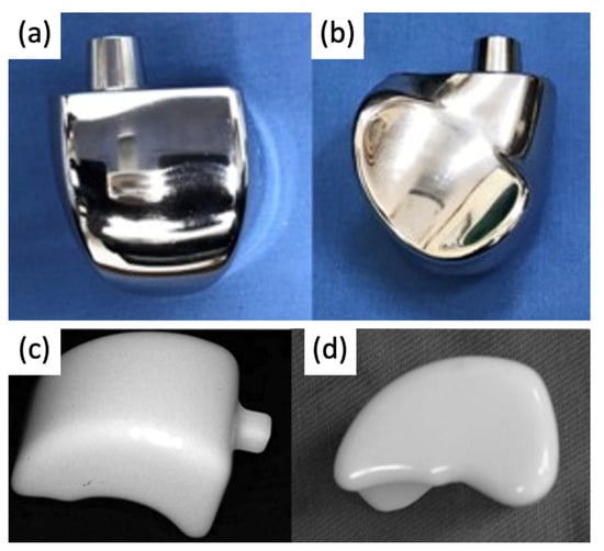
Figure 23. Labeled X-ray of (
A) preoperative and (
B) TAA implant performed on a patient, consisting of a polyethylene tibial component and metallic talar component
[14][26].
2.2. Current Total Ankle Arthroplasty Implants
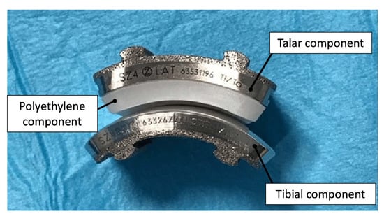
Second through fourth-generation TAA implants consist of three components: a metal component attached to the tibia, a metal component attached to the talus, and a mobile plastic implant between the two
[15][16][27,28], as shown in
Figure 34. Advancements in this design provided almost normal kinematic function of the joint in plantarflexion/dorsiflexion, inversion/eversion, and tibial rotation, resulting in overall improved gait performance as well as increased pain relief compared to AA outcomes
[14][16][26,28]. Existing reviews have concluded that complication rates in patients with TAA (19.7%) in recent years have also been lower than in patients with AA (26.9%)
[17][29]. However, complication and failure rates remain higher than those for knee and hip arthroplasties, still making TAA a controversial technique in clinical use. Revision rates following TAA have also been reported as high as 7.9%, compared to 5.4% for AA
[17][29], which has been largely attributed to the loosening of the implant.
Figure 34. Photograph of 3-part TAA implant composed of a metal tibial component, a mobile polyethylene insert, and a metal talar component
[18][30].
2.3. Advancements in Total Ankle Arthroplasty Design and Manufacturing
Loosening of TAA implants has been attributed to the mal-positioning of the implant, leading to altered motion and pressures at the contact surface
[12][24]. Furthermore, end-stage osteoarthritis (OA) can lead to significant degradation of the articular surface of the tibia and talus, which may lead to deformity of the underlying osteochondral bone and properties of the supporting soft tissue. Thus, mass-produced implants limited to mimicking the anatomy of a healthy joint can be highly unstable and unsupported in an OA joint. However, AM permits the fabrication of personalized TAA implants and reduces the risk of implant failure and patient discomfort.
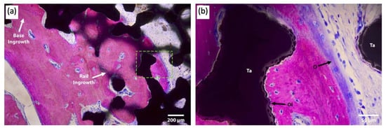
Attention has been paid to the bone–implant interface of TAA implants. In addition to hydroxyapatite and porous surface coating technologies commonly used in other joint replacements, a recent case study reported the use of a third-generation TAA implant, comprised of a titanium alloy tibial component and cobalt–chromium (CoCr) talar component, both coated with porous tantalum (P-Ta) (80% porosity)
[19][31]. Three years following implantation, the authors performed a histological analysis of the intact implant (
Figure 45).
Figure 45. Light microscopy images of the talar/bone component stained with Sanderson’s rapid bone stain (SRBS) 3.5 years post-operation. Mineralized bone was stained pink, osteoid and non-mineralized soft tissue were stained blue, and the color black is for tantalum. (
a) Low-magnification image of explants showing bony ingrowth into the porous tantalum implant, with healthy remodeling. (
b) Higher-magnification view of the green dotted box in image (
a) showing osseointegration to the porous tantalum with the patient’s newly formed bone. Ta: tantalum, O: osteoid, OI: osseointegration
[20][32].
3. Total Talus Replacement
The talus articulates with the fibula and tibia to form the ankle joint, allowing dorsiflexion and plantarflexion of the foot, and with the calcaneus to make the subtalar joint, allowing inversion and eversion of the foot (for anatomical pictural representation, reference
Figure 12: Graphic of bones in the ankle joint, including talus, fibula, tibia, calcaneus, and surrounding bones). It is responsible for the transmission of weight and pressure forces from the lower leg to the foot and is covered by articular cartilage for smooth movement against its neighboring bones
[21][37].
Total talus arthroplasty (TTA) is an alternative orthopedic procedure that was developed as a treatment in cases of total talar compromise due to avascular necrosis, trauma, osteonecrosis, tumor-induced bone defects, or talar body collapse due to complications of TAA
[6][22][23][24][25][26][27][28][18,38,39,40,41,42,43,44].
3.1. The Evolution of Total Talus Arthroplasty Implants
Prior to the advent of TTA, the recommended treatment for trauma or avascular necrosis of the talus was either arthrodesis or talectomy paired with simultaneous tibiocalcaneal arthrodesis; however, both options often resulted in the loss of ankle and foot function, as well as hindfoot instability in the former and discrepant leg shortening in the latter. TTA was designed to replace the talus while preserving the motion and work of the ankle and foot
[22][38].
The bone consists of three parts: head, neck, and body. In first-generation TTA implants (
Figure 58), the prosthesis consisted of two components: the talar body and a peg for attachment into the talar neck. Only the talar body was replaced, and the talar neck was fixated on the prosthetic stem with bone cement. Satisfactory results were reported in post-operative evaluations, with preserved joint stability and increased mobility of the ankle and foot. However, there were noted issues with prosthesis congruence and prosthesis failure where the prosthesis stem had sunken into the talar neck
[22][23][38,39].
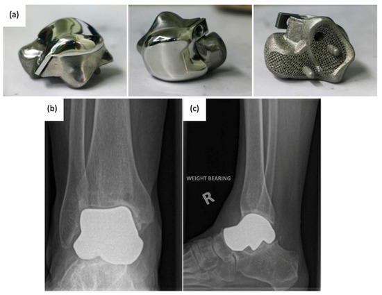
Figure 58.
(a
,b
) First-generation talar body prosthesis with an attachment peg and (c
,d) second-generation prosthesis [22][24].
3.2. Current Total Talus Arthroplasty Implants
Since the talus is not stabilized by any muscular attachments, its positioning primarily depends upon the support of the surrounding bones and ligaments, and thus, the most important factor for prosthesis survival is implant congruence with articular surfaces [29]. Recently introduced third-generation TTA implants ( ) second-generation prosthesis [38,40].
3.2. Current Total Talus Arthroplasty Implants
Since the talus is not stabilized by any muscular attachments, its positioning primarily depends upon the support of the surrounding bones and ligaments, and thus, the most important factor for prosthesis survival is implant congruence with articular surfaces [45]. Recently introduced third-generation TTA implants (Figure 6) are described as custom total talar prostheses, which circumvents the earlier concerns of loosening and sinking between the talar neck and prosthesis. Many groups have designed TTA implants using the patient’s healthy contralateral talus as a model for AM, which can be made into forms that may not have been possible to achieve using the current production method [30]. Custom third-generation TTA implants have been manufactured primarily by SLS, using materials including cobalt–chrome, nickel-plated cobalt, titanium alloy, and alumina ceramics. These implants have demonstrated retention of mobility, rapid pain relief, and preserved joint height, as well as a shorter duration of restricted weight bearing [26][27][28][31][32].
9) are described as custom total talar prostheses, which circumvents the earlier concerns of loosening and sinking between the talar neck and prosthesis. Many groups have designed TTA implants using the patient’s healthy contralateral talus as a model for AM, which can be made into forms that may not have been possible to achieve using the current production method [46]. Custom third-generation TTA implants have been manufactured primarily by SLS, using materials including cobalt–chrome, nickel-plated cobalt, titanium alloy, and alumina ceramics. These implants have demonstrated retention of mobility, rapid pain relief, and preserved joint height, as well as a shorter duration of restricted weight bearing [42,43,44,47,48].
Figure 69.
(a
) 3D-printed third-generation total talus prosthesis and post-operative X-rays of implanted 3D-printed third-generation TTA prosthesis, (b
) anterior–posterior, and (c) lateral views [30][33]. ) lateral views [46,49].
3.3. Advancements in Total Talus Arthroplasty Design and Manufacturing
Third-generation TTA with complete, custom talus implants has shown promising results for post-operative pain relief and mobility; however, the current production method is costly and slow. In a 55-patient case study examining the use of ceramic TTA implants, CT imaging was used to generate a wire model, from which a stereolithographic model was generated. From the model, an alumina-ceramic prosthesis was created, with the entire manufacturing process taking approximately 4 weeks [27]. As AM becomes an increasingly popular method for TTA implant manufacturing, attention is being paid to faster prosthesis design, resulting in optimized anatomical fit within a shorter timeline.
Third-generation TTA with complete, custom talus implants has shown promising results for post-operative pain relief and mobility; however, the current production method is costly and slow. In a 55-patient case study examining the use of ceramic TTA implants, CT imaging was used to generate a wire model, from which a stereolithographic model was generated. From the model, an alumina-ceramic prosthesis was created, with the entire manufacturing process taking approximately 4 weeks [43]. As AM becomes an increasingly popular method for TTA implant manufacturing, attention is being paid to faster prosthesis design, resulting in optimized anatomical fit within a shorter timeline.
4. Ankle Prosthetics
Ankle prosthetic devices are indicated for patients with various lower extremity impairments, including lower limb amputations resulting from trauma or underlying disease, as well as neurological deficits due to spinal cord injuries or strokes. In patients with lower extremity amputations, recent developments in ankle prosthetic devices aim to decrease metabolic costs and improve mobility and gait while simultaneously increasing comfort for the patient. Additionally, in patients with lower extremity neurological deficits, ankle prosthetics have the potential to alleviate many negative health consequences, including obesity syndrome, various chronic diseases, decreased bone health, and pressure injuries
[34][52].
Ankle prosthetics can be divided into three main categories, including passive, quasi-passive, and active prosthetic devices, with studies providing evidence for the superiority of quasi-passive and active devices
[35][53]. Passive prosthetics do not contain an external energy source, while active prosthetic devices, otherwise known as powered exoskeletons, have demonstrated significant improvements in functionality, including improved accommodation for terrain and faster walking speed
[36][54].
4.1. Evolution of Ankle Prosthetics
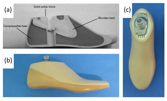
Conventional, passive prosthetic feet include the Solid Ankle Cushion Heel (SACH) foot and Energy Storage and Return (ESAR) prosthetics. After its introduction in 1980, the SACH foot became the standard due to its availability, inexpensiveness, and durability. The SACH foot is a basic design consisting of wood, rubber, and compressible foam materials (
Figure 710). The SACH foot design has been shown to provide flexibility based on the height and weight of the patient and provide some degree of mobility in dorsiflexion only
[37][56].
Figure 710. (
a) Labeled drawing of a SACH foot cross-section, including wood, rubber, and compressible foam materials, and (
b,
c) photograph of SACH foot prosthetic including a cosmetic shell
[38][39][59,60].
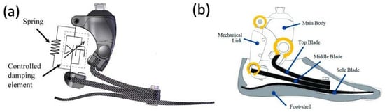
ESAR feet are designed to store elastic energy during midstance and subsequently release energy during push-off. Multiple variations of the ESAR foot exist, with the basic design consisting of multiple flexible blades attached to an adaptor with a mechanical link (
Figure 811). ESAR implants are typically composed of carbon fiber or carbon fiber-reinforced polymers, and groups have also employed AM using SLS to manufacture patient-specific implants with desired stiffnesses to improve gait
[40][61].
Figure 811. (
a) Appearance of constructed functional ESAR prosthetic and (
b) labeled graphic of the ESAR foot design with the top blade, middle blade, sole blade, mechanical link, and main body
[41][62].
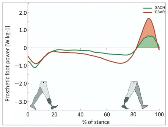
ESAR prosthetic feet generate greater energy, reduce metabolic costs, and increase self-selected walking speeds when compared to the conventional SACH foot
[42][63]. A study comparing the ESAR foot to SACH feet demonstrated that the ESAR foot allowed for higher push-off power and increased intact step length without decreasing backward stability
[43][64] (
Figure 912).
Figure 912. Push-off power of the prosthetic foot as a function of normalized stance time [43].
4.2. Early Powered Exoskeletons in Gait Rehabilitation
Early robot-assisted gait training was first initiated in a clinical therapeutic setting, often attached to training devices such as treadmills. These initial models were designed as orthotic devices with body-weight support. For instance, the Lokomat (
Push-off power of the prosthetic foot as a function of normalized stance time [64].
4.2. Early Powered Exoskeletons in Gait Rehabilitation
Early robot-assisted gait training was first initiated in a clinical therapeutic setting, often attached to training devices such as treadmills. These initial models were designed as orthotic devices with body-weight support. For instance, the Lokomat (Figure 10) is composed of a motorized exoskeleton that provides guidance forces onto the knee and hip joints and has been shown to increase the range of motion about the ankle joint. Briefly, the motorized exoskeleton consists of a DC motor with helical gears to direct the trajectory of the joints [44]. The Lokomat device has been used successfully in gait rehabilitation for patients with brain or spinal cord injuries that exhibit muscle weakness, spasticity, or abnormal muscular activation patterns.
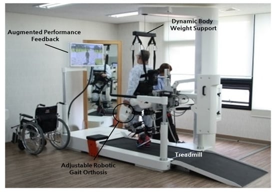
4) is composed of a motorized exoskeleton that provides guidance forces onto the knee and hip joints and has been shown to increase the range of motion about the ankle joint. Briefly, the motorized exoskeleton consists of a DC motor with helical gears to direct the trajectory of the joints [70]. The Lokomat device has been used successfully in gait rehabilitation for patients with brain or spinal cord injuries that exhibit muscle weakness, spasticity, or abnormal muscular activation patterns.
Figure 104. Lokomat device used for gait rehabilitation following lower-limb disability, brain injury, or spinal cord injury. The device consists of a treadmill, body weight support, and powered leg orthosis [44].
4.3. Battery-Powered Exoskeletons in Congenital Disorder Gait Rehabilitation
Lokomat device used for gait rehabilitation following lower-limb disability, brain injury, or spinal cord injury. The device consists of a treadmill, body weight support, and powered leg orthosis [70].
4.3. Battery-Powered Exoskeletons in Congenital Disorder Gait Rehabilitation
As powered exoskeletons advance to more mobile forms that allow patients to move overground in an unrestricted area, applications are being explored in congenital neurological disorders like cerebral palsy (CP). Previous therapies for these patients with pathological gaits that ultimately progressed to reduced walking ability in adolescence included physical therapy, orthotics, muscle injections, and surgeries, which did not necessarily show improvement in gait. The possibility of using wearable battery-powered exoskeletons is being explored to reinforce more favorable walking patterns in CP patients
[45][72].
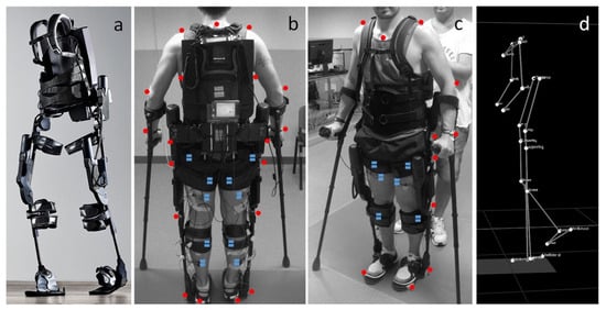
These exoskeletons (
Figure 115) are composed of an onboard battery that powers high-performance DC motors. This structure is actuated onto a pulley aligned with each ankle joint via a Bowden cable transmission that helps to mount the heaviest components of the exoskeleton onto the patient’s torso. In addition, torque sensors are mounted in line with the exoskeleton’s ankle joint, allowing for feedback-based motor control. Under the ball of each foot, additional foot sensors allow for the implementation of the plantar flexion assist on the mode of the exoskeleton, adding torque to the ankle joint to mimic the shape and timing of normal physiological ankle movement.
Figure 115. (
a) Photograph of exoskeleton Ekso 1 equiped with 4 powered motors at the hips and knees, 2 powered joints at the hip and knee, and a semi-rigid unpowered ankle joint; (
b,
c) patient utilizing mobile ankle exoskeleton with the aid of crutches to maintain balancing. The system was equiped with motion analysis markers (red dots) and electromyographs (blue dots) for gait analyis; (
d) kinematic data resulting from the motion capture system
[45][72].
4.4. Powered Exoskeletons in Stroke Rehabilitation
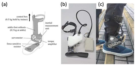
Stroke patients commonly suffer from foot drop syndrome, which equates to a higher falling risk, making effective gait rehabilitation essential to improve patients’ quality of life and independence. Prior gait training systems generally confined patients to a treadmill-like setting and may not contribute to the ultimate goal of independent walking on real-world surfaces. Passive ankle–foot orthotics have also been used in conjunction with conventional physical therapy, but they also limit the patient’s range of motion about the ankle joint.
Powered exoskeletons are being applied in the gait rehabilitation of both chronic and sub-acute stroke patients
[46][47][73,74]. One such model being used is a modified form of an ankle–foot orthotic coupled to a rotatory servomotor and torque amplifier that provides powered assistance in plantarflexion and dorsiflexion (
Figure 126).
Figure 126. (
a) Graphic of powered ankle exoskeleton used in gait training of stroke survivors, including labels of rotatory servomotor and torque amplifier and (
b,
c) photographs of a manufactured powered ankle exoskeleton used on stroke patients
[46][47][73,74].
4.5. Powered Exoskeletons in Lower Extremity Trauma Patients
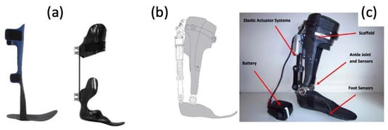
More and more are lower extremity trauma patients opting for limb reconstruction surgeries over amputations, making them candidates for wearable foot and ankle exoskeletons, termed ankle–foot orthotics (AFOs). More traditional forms of AFOs are passive (
Figure 137).
Figure 137. (
a) Photographs of traditional, passive AFOs and (
b,
c) a graphic and photograph of a powered PFO, including labels of elastic actuator and ankle/foot sensors
[48][75].