Effective ROS in AOPs of PFASs vary based on the oxidizing agents and their activation methods. Free radicals, such as •OH, sulfate radicals (SO
4−•), and superoxide radicals (•O
2−), as well as nonradicals like singlet oxygen (
1O
2) and holes (h
+), have been identified as dominant ROS that contribute individually or synergistically to the defluorination and destruction of PFASs through advanced oxidation
[24][47]. Fenton and Fenton-like processes, using hydrogen peroxide (H
2O
2) as the oxidant, generate •OH as the effective ROS when activated by Fe
2+ or other transition metal-based chemicals or materials. Activated persulfate systems, utilizing persulfate (PDS, S
2O
82−) or peroxymonosulfate (PMS, HSO
5−), primarily generate SO
4−• as the dominant ROS and exhibit reactivity due to the high redox potential (+ 2.5 V~3.1 V) and long lifetime (3.4 × 10
−5 s) of SO
4−•
[25][26][48,49]. Meanwhile, it should be noted that the activation methods of PMS make a big difference to the types of ROS, e.g., SO
4−• via activation with carbon materials, SO
4−• and •OH via thermal and radiation activation, SO
4−• and peroxymonosulfate anion radicals (SO
5•
−) via transition metal activation, and •O
2− and
1O
2 via alkali activation
[27][50]. In addition, photogenerated h
+ acts as a powerful ROS that directly oxidizes PFASs or converts H
2O/O
2 to •OH/•O
2−, thereby generating more ROS
[28]. Electrochemical processes induce the rapid generation of different ROS at the anode or facilitate electron transfer to the anode
[29][51].
2.2. Principles of Photocatalytic AOPs for PFAS
Photocatalytic AOPs for FPAS are developed based on direct photo-degradation, achieved by breaking apart the C−F bonds using light of a specific wavelength. The direct photolysis process requires a match between the adsorption spectrum of the chemical bonds and the emission spectrum of the light, with the wavelength of the light playing a crucial role
[30][52]. For example, PFOA has demonstrated strong UV adsorption and fast degradation at 185 nm
[31][32][53,54], while light with a wavelength above 220 nm is barely absorbed by PFASs
[33][34][29,55]. In photocatalytic AOPs of PFASs, the indirect photo-oxidation process is characterized by decarboxylation followed by defluorination, believed to be related to the photoinduced holes that exhibit a strong oxidizing capacity for organics. These holes work synergistically with other ROS to enhance PFAS degradation
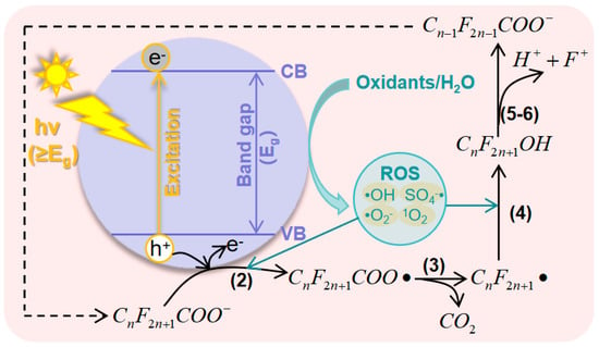
[35][36][56,57]. The system of photocatalytic AOPs consists of three components: the light, oxidant, and photocatalyst. There are two principles of PFAS degradation in photocatalytic AOPs: direct oxidation by photogenerated holes and co-oxidation with other ROS that are generated at the surface of catalysts with the assistance of the holes. The general process of PFAS degradation in photocatalytic AOPs can be described as follows: (1) Catalysts absorb light with energy (hv) equal to or greater than the band gap, which excites electrons from the valence band (VB) to the conduction band (CB), creating holes in the VB. (2) The generated electron−hole (e
−−h
+) pairs migrate to the surface of catalysts and react with the adsorbed PFAS. (3) The e
−−h
+ pairs react with precursors and generate ROS which assist in PFAS decomposition.

The general mechanism of photocatalytic AOPs for PFAS degradation is summarized in
Figure 2, where the PFAS is represented by PFAC. Photocatalysts play a crucial role in this process, as they are responsible for generating effective ROS and binding PFAS molecules. Both of these factors determine the efficiency of degradation
[23][46]. Therefore, the construction and structure engineering of photocatalysts have garnered significant research interest.
Figure 2. Mechanisms of photocatalytic AOPs for the degradation of PFASs.
2.3. Principles of Electrocatalytic AOPs for PFASs
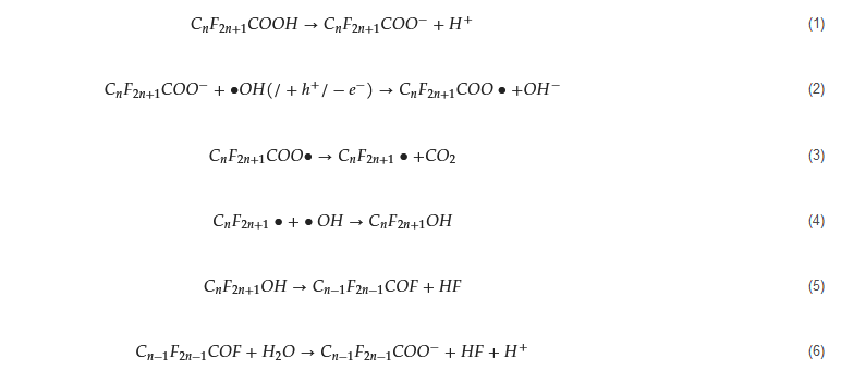
There are two types of electrocatalytic AOPs for PFASs: direct electro-oxidation and indirect electrochemical oxidation. Direct electro-oxidation is a simple AOP that occurs on the surface of an electrode (anode) with a direct transfer of electrons. It relies on the in situ generation of ROS (e.g., •OH) or the direct transfer of electrons from the PFAS to the anode [37]. On the other hand, indirect electrochemical oxidation processes are the primary electrocatalytic AOP for organics treatment. Unlike direct electro-oxidation, electrons in this process act as mediators or assist in the generation of powerful ROS [29]. For example, the degradation of PFASs starts with the release of electrons, forming C Mechanisms of photocatalytic AOPs for the degradation of PFASs.
2.3. Principles of Electrocatalytic AOPs for PFASs
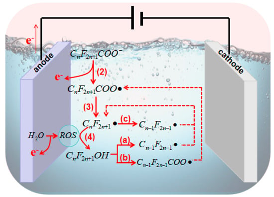
There are two types of electrocatalytic AOPs for PFASs: direct electro-oxidation and indirect electrochemical oxidation. Direct electro-oxidation is a simple AOP that occurs on the surface of an electrode (anode) with a direct transfer of electrons. It relies on the in situ generation of ROS (e.g., •OH) or the direct transfer of electrons from the PFAS to the anode [60]. On the other hand, indirect electrochemical oxidation processes are the primary electrocatalytic AOP for organics treatment. Unlike direct electro-oxidation, electrons in this process act as mediators or assist in the generation of powerful ROS [51]. For example, the degradation of PFASs starts with the release of electrons, forming CF2n+1COO• (Equation (2)); this occurs under an anode potential higher than the oxidation potential of the PFAS [38]. Additionally, electrocatalytic AOPs can produce radicals and oxidants during the electrode process. This includes •OH, which is strongly adsorbed onto the anode surface (M), as shown in Equation (9), H COO• (Equation (2)); this occurs under an anode potential higher than the oxidation potential of the PFAS [61]. Additionally, electrocatalytic AOPs can produce radicals and oxidants during the electrode process. This includes •OH, which is strongly adsorbed onto the anode surface (M), as shown in Equation (9), HO from the dimerization of •OH (Equation (10)), and ozone (O3) from the discharge of water molecules (Equation (11)) [39]. These products are highly reactive with certain intermediate products during the decarboxylation and defluorination processes of PFASs, contributing to the efficiency of degradation.
The general mechanism of electrocatalytic AOPs for PFAS degradation is illustrated in
) from the discharge of water molecules (Equation (11)) [62]. These products are highly reactive with certain intermediate products during the decarboxylation and defluorination processes of PFASs, contributing to the efficiency of degradation.

The general mechanism of electrocatalytic AOPs for PFAS degradation is illustrated in . According to previous studies, after the formation of CF2n+1• [40], there several approaches for further mineralization. Process (a) and (b) initially undergo a reaction with •OH to form C • [63], there several approaches for further mineralization. Process (a) and (b) initially undergo a reaction with •OH to form CF2n+1OH (Equation (4)). In process (a), reactions from Equation (12) to Equation (13) occur [41], whereas in process (b), reactions from Equation (14) to Equation (16) take place [42][43]. Aside from •OH, other anodic ROS such as O OH (Equation (4)). In process (a), reactions from Equation (12) to Equation (13) occur [64], whereas in process (b), reactions from Equation (14) to Equation (16) take place [65,66]. Aside from •OH, other anodic ROS such as O also react with CF• (Equation (17)), and the oxidation product CFOO• can react with other perfluoro-alkoxy radicals (RCOO•) (Equation (18)). The resulting CFO• then decomposes into CF2n−1• for further degradation in a new cycle (Equation (19)) [40][41][42][44][45]. The third pathway (c) follows the reactions from Equation (17) to Equation (19).
• for further degradation in a new cycle (Equation (19)) [63,64,65,67,68]. The third pathway (c) follows the reactions from Equation (17) to Equation (19).
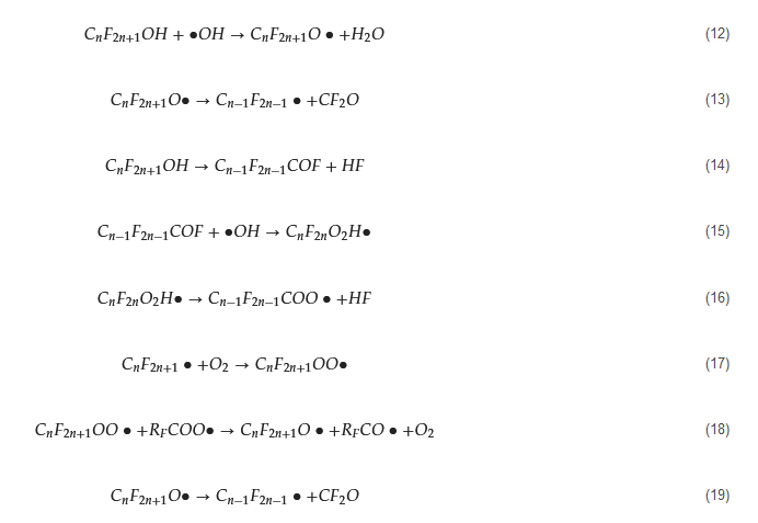
Figure 3. Mechanisms of electrocatalytic AOPs for the degradation of PFASs.
In electrocatalytic processes, oxidation primarily occurs on the anode. Therefore, the choice of anode materials (i.e., electrocatalysts) plays a crucial role in electrocatalytic AOPs for PFAS degradation. The behavior of PFAS degradation can vary depending on the type of anode material used. Anode materials are classified into two types based on the interactions between the adsorbed •OH on the anode surface and the degradation of organics: active anodes and nonactive anodes. Active anodes, such as Ti/SnO2
−Sb/MnO2 [40], have a low potential for O [63], have a low potential for O2
evolution and are distinguished from non-active anodes, such as Ti/SnO2−Sb [46], by their ability to transform M(•OH) into strong oxidants. Generally, anode materials with higher O −Sb [69], by their ability to transform M(•OH) into strong oxidants. Generally, anode materials with higher O2-evolution potential exhibit weaker interactions between M(•OH) and their surface, but they have higher reactivity towards PFASs [29]. -evolution potential exhibit weaker interactions between M(•OH) and their surface, but they have higher reactivity towards PFASs [51].
3. Photocatalysts in AOPs for PFAS Degradation
3.1. Metal Oxide-Based Materials
.1. Metal Oxide-Based Materials
Metal oxides, such as TiO2
, In2
O3
, and Ga2
O3, have long been used as traditional semiconductors in the photocatalytic degradation of organics in water. These metal oxides have been extensively studied for PFAS degradation [23][47][48][49]. TiO , have long been used as traditional semiconductors in the photocatalytic degradation of organics in water. These metal oxides have been extensively studied for PFAS degradation [27,46,76,77]. TiO2
-based materials, in particular, have been widely used as photocatalysts since the discovery of water splitting on a TiO2 anode by Fujishima and Honda in 1972 [50]. Though TiO anode by Fujishima and Honda in 1972 [78]. Though TiO2
has shown promise in heterogeneous photocatalysis due to its strong UV absorption, non-toxicity, and long-term photostability, it is not efficient for photocatalytic PFAS degradation. This is due to its narrow spectral range, wide bandgap (3.0 eV for the rutile phase and 3.0 eV for the anatase phase), low electron-hole separation efficiency, and poor adsorption performance. Therefore, modifications of TiO2 are necessary to enhance its photocatalytic activity. Strategies for modification include metal/nonmetal element doping, carbon material loading, and heterostructure construction. To date, doping with Fe [51], Cu [51], Pb [48][52], Pt [53], Pd [54], Ag [55] in TiO are necessary to enhance its photocatalytic activity. Strategies for modification include metal/nonmetal element doping, carbon material loading, and heterostructure construction. To date, doping with Fe [79], Cu [79], Pb [24,76], Pt [80], Pd [81], Ag [82] in TiO2 for enhanced PFAS degradation has been studied, as well as the co-doping of metals, such as Fe/Nb [56]. Metal doping involves controlling the doping amount and regulating the pH of the solution to avoid the competitive adsorption of OH for enhanced PFAS degradation has been studied, as well as the co-doping of metals, such as Fe/Nb [70]. Metal doping involves controlling the doping amount and regulating the pH of the solution to avoid the competitive adsorption of OH−
on the catalyst surface under alkaline conditions.
In2
O3
is a PFAS affinity material with a narrow bandgap of 2.8 eV, exceptional photocatalytic activity, and sensitivity to visible light. When compared to TiO2
, In2
O3 has shown a remarkable 8.4-fold increase in the degradation rate coefficient of a PFAS (PFOA) under UV irradiation. These findings suggest it is a promising photocatalyst for PFAS decomposition [23]. Modifications are necessary for In has shown a remarkable 8.4-fold increase in the degradation rate coefficient of a PFAS (PFOA) under UV irradiation. These findings suggest it is a promising photocatalyst for PFAS decomposition [46]. Modifications are necessary for In2
O3
due to its limitations, i.e., its low specific surface area and the rapid recombination of photogenerated electron-hole pairs. One effective approach is the generation of oxygen vacancies on the In2
O3 surface, which enhances its photocatalytic performance. Additionally, nanostructures like nanospheres [19], (porous) nanosheets, and nanocubes [57][58] have been developed to provide adsorption sites for PFOA and oxygen atom binding sites in the carboxyl groups. These modifications ultimately contribute to the improved photocatalytic decomposition of PFOA. Several composite materials have been reported, such as g-C surface, which enhances its photocatalytic performance. Additionally, nanostructures like nanospheres [42], (porous) nanosheets, and nanocubes [91,92] have been developed to provide adsorption sites for PFOA and oxygen atom binding sites in the carboxyl groups. These modifications ultimately contribute to the improved photocatalytic decomposition of PFOA. Several composite materials have been reported, such as g-C3
N4
−In2
O [93], CeO2
−In2
O [94], and MnOx−In2
O [74].
Ga2
O3
has excellent conductivity and tunable optical properties, despite its wide band-gap (4.9 eV). Studies have demonstrated its remarkable UV photocatalytic activity against PFASs, specifically in the context of PMS-assisted photocatalytic AOPs. The Ga2
O3
/PMS/UV system, with SO4−
• and •O2− as key ROS, achieves 100% degradation within 60 min [ 
 The general mechanism of photocatalytic AOPs for PFAS degradation is summarized in Figure 2, where the PFAS is represented by PFAC. Photocatalysts play a crucial role in this process, as they are responsible for generating effective ROS and binding PFAS molecules. Both of these factors determine the efficiency of degradation [23][46]. Therefore, the construction and structure engineering of photocatalysts have garnered significant research interest.
