Your browser does not fully support modern features. Please upgrade for a smoother experience.
Please note this is a comparison between Version 1 by Martin Scheurer and Version 2 by Jason Zhu.
Textile-reinforced concrete (TRC) is a composite material consisting of a concrete matrix with a high-performance reinforcement made of technical textiles. TRC offers unique mechanical properties for the construction industry, enabling the construction of lightweight, material-minimized structures with high load-bearing potential. In addition, compared with traditional concrete design, TRC offers unique possibilities to realize free-form, double-curved structures.
- textile-reinforced concrete
- buildtech
- composites
1. Introduction
The construction industry is a very important part of the global economy, making up about 13% of global gross domestic product and employing about 7% of the global working population [1]. At the same time, the construction sector is responsible for about 33% of global energy consumption, about 40% of global raw material consumption, and about 40% of global solid waste generation [2][3][4][2,3,4]. Therefore, any initiative to reduce global greenhouse gas emissions will have to take the construction sector into account [2].
Megatrends such as increasing global population, increasing urbanization, and increasing amount of used living space per resident lead to a further projected increase in materials and energy used in the construction industry [5]. Continuing construction business as usual may more than double global raw material extraction until 2050 [6][7][6,7].
These facts and figures demonstrate the importance of a paradigm shift in the construction industry. While more construction for the increasing global population is inevitable, sustainability concerns need to be addressed swiftly and comprehensibly. Regulators in several countries are planning to or have already introduced measures to limit resource and energy usage in the construction industry [8].
One of the main drivers of greenhouse gas emissions and energy use in the construction industry is the production of ordinary cement, which itself is responsible for about 8% of global greenhouse gas emissions [9]. Cement is a component of concrete (the other components being water and aggregates, such as sand or gravel). Concrete is the second most used material in the world, only surpassed by water [10]. Concrete has a high compressive strength but low tensile strength. If tensile or bending loads are present, concrete is commonly reinforced, often using steel bars or grids, which carry the tensile load [11]. However, since the steel reinforcement corrodes when in contact with air, a minimum concrete cover is required to protect the steel reinforcement from corrosion [12]. This minimum concrete cover is often thicker than required by the present loads, leading to increased and mechanically redundant material usage [13].
Novel materials with lower energy and material usage as well as lower greenhouse gas emissions are one possibility to reduce the impact of the construction industry. One possible novel material combination, which has been researched since the late 1990s, is textile-reinforced concrete (TRC). In TRC, the steel reinforcement is substituted by a reinforcement made of technical textiles [13]. These textiles are usually made of high-performance materials such as glass or carbon fibers, which do not corrode when in contact with air and therefore enable the reduction in the concrete cover to a minimum [14]. Thereby, TRC enables the construction of lightweight, thin-walled concrete elements, such as bridges [15], precast elements [16][17][18][16,17,18], and facades [19][20][21][19,20,21]. Another application of TRC is in the retrofitting of existing concrete structures [22][23][22,23]. Another example of the use of TRC is the building “CUBE” in Dresden, Germany, which is the first building constructed entirely from TRC [24].
2. Robot-Based Manufacturing Methods for Reinforcement Textiles
Robot-supported manufacturing technologies enable the production of resource-saving and cost-efficient but also freely formable and arbitrarily designable textile reinforcement structures for concrete constructions. These promising technologies are based on industrial six-axis robots, which are highly versatile machines that can be programmed to perform various tasks in manufacturing and other industries. They are capable of precise and repetitive movements, making them ideal for tasks that require speed, accuracy, and consistency. Industrial robots can also operate without fatigue and in hazardous environments or perform tasks that are too dangerous for humans. A six-axis industrial robot has six degrees of freedom, allowing the robot to perform translational (X, Y, Z) and rotational (A, B, C) movements. This allows the robot to work in three dimensions and move its tools to any position within its reach, enabling the on-demand creation of free-form textile reinforcement structures. Six-axis robots are widely used in the automotive, electronics, and aerospace industries due to their beneficial properties such as productivity, increases in quality from high-precision and high-repetition accuracy, variable adaptability, and reduced labor costs by replacing humans with robots. Thanks to their highly variable movement capabilities, they are also able to manipulate yarn-guiding tools in order to deposit the yarn, for instance, on a yarn fixation rack, on winding cores, or simply free in space. For this purpose, carbon fiber heavy tows (CFHT) Tenax-E STS 40 E23 48K (Teijin Carbon Europe GmbH, Wuppertal, Germany) with a fineness of about 3200 tex are often used to efficiently manufacture the nonmetallic reinforcement structures [25][79]. To pave the way for novel resource-saving and cost-efficient textile reinforcement structures, researchers have developed distinctive robot-based machine technologies. Several robotic yarn deposition technologies already exist or are currently being developed for the production of textile reinforcement structures for the construction industry or fiber-reinforced plastics for the composites market. All robotic manufacturing technologies consist of several functional modules, namely the manipulating robot, the yarn deposition tool—which performs the function of storing, guiding, and impregnating the yarn—and the workpiece carrier, which is used to temporarily fix the reinforcement structure. However, they all differ in their mode of operation. There are robotic manufacturing processes that have been developed to meet the needs of the construction industry (focusing on the reinforcement of concrete components) and those that have emerged from other industries (e.g., architecture or automotive). Basically, there are different ways to produce textile reinforcement structures—either by manipulating the yarn placement tool, where the workpiece carrier is fixed, or by moving the workpiece carrier while the yarn placement tool stands still, as in the winding, using a winding core [26][27][80,81]. Figure 1a,b show the two basic process principles of robotic yarn deposition technologies, where a single robot moves either the tool or the workpiece carrier. Collaboratively used robot systems consist of various six-axis robots and, in some cases, of additional unmanned aerial vehicles (UAVs) and climbing robots, as in the translational cross-winding technique or the filament-winding technique by means of UAVs [28][29][82,83]. They are also being used to produce large-scale shell elements with membranous outer appearance exclusively using both preimpregnated and freshly impregnated rovings [29][30][83,84].2.1. Process Principle A
The technological design by von Zuben et al. is shown in Figure 1a using freshly impregnated carbon fiber heavy tows ((CFHTs), used here is a roving Tenax-E STS 40 E23 48K from Teijin company, and the matrix is Biresin CR84/CH120-6 from SIKA company)—the yarn spool and the impregnation unit are both manipulated by the robot—for the production of planar and lattice-like reinforcement structures [15]. Here, yarn impregnation is only performed immediately prior to yarn deposition. The operation consists of the robot manipulating the yarn deposition tool. The workpiece carrier is fixed. Von Zuben et al. focus on the use of conventional epoxy resin as an impregnation agent; so, the plant technology is also designed for this two-component resin system [31][85]. This manufacturing principle can already be used to produce planar 2D reinforcement structures with cut-free geometries.2.2. Process Principle B
Another technological approach, shown in Figure 1b, is the winding technique using a winding core. The workpiece carrier is manipulated by the robot arm, while the yarn tool is stationary on the floor [32][86]. An impregnation bath with a yarn eye for precise deposition can be used as the yarn tool. Michel et al. used a mineral impregnation of the carbon fibers. Due to the homogeneity of the mineral material, a high bond to the concrete is achieved, and the roving can be processed flexibly within a process window of four hours after impregnation [33][60]. Alternatively, preimpregnated CFHTs can be used to produce extremely lightweight reinforcement structures with graded fiber distribution, such as a reinforcing cage for a balcony [27][81].2.3. Process Principle C
The 3D coreless filament winding technology with two cooperating robots by Minsch et al., shown in Figure 1c, is another production technology being developed [34][87]. The 3D coreless filament winding uses a translational cross-winding technique to produce truss-like structures. The yarn impregnation process is conducted off the robotic manipulation on a fixed impregnation unit. The freshly impregnated carbon fiber yarn is delivered directly afterwards to the filament winding tube. The yarn is a Toray T620SC-24000-50C roving (CFHT) in combination with epoxy resin Hexion MGS LR385 and hardener LH 386. The robot simply manipulates the freely fed yarn using a yarn guide tube, as the impregnation tool is stationary on the floor and the yarn is therefore impregnated outside the robot handling process. This technology was originally developed in response to the challenge of providing lightweight materials for energy-reduced manufacturing processes in the automotive industry.2.4. Process Principle D
A fourth robot-assisted technology for direct yarn deposition is shown in Figure 1d with the collaboratively working multirobot system by Knippers et al. [35][36][88,89]. This robotic system uses robotic systems consisting of six-axis robots, UAVs, and optionally, climbing robots [29][37][83,90]. The workpiece carrier is fixed, and the individual robots manipulate the preimpregnated yarn. The yarn impregnation tool is also stationary. In a different application, where the textile topology is more complex or the deposition process requires additional degrees of freedom, Knippers et al. use a rotating, single-axis workpiece carrier to provide additional uniaxial motion [38][91].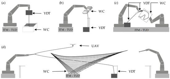
2.5. Future Process Principle E
A technological outlook is represented by the novel robotic manufacturing process with a robotic yarn impregnation and an intelligent yarn fixation module in Figure 2, which will be implemented in the near future. The yarn impregnation module consists of several submodules, which are mounted at different points of the robot. The impregnation material storage and their feed pumps are designed as a kind of backpack solution. They are mounted on the main axis (axis 1). The yarn spool, the piston rod cylinder for regulating the yarn tension, and the mixing chamber are mounted on the robot’s swivel arm. Here, various impregnation agents as two-component polymer systems and aqueous water dispersions are supposed to be homogenized. In the future, it should also be possible to process photopolymers with this impregnation module. The yarn fixation module, controlled by the higher-level programmable logic controller, is located within reach of the robot arm. The controller of the yarn fixation module interacts with the robot controller via a PROFIBUS interface. This allows the recipe sequence of the fixation module to be matched to the generated winding paths. The 3D yarn fixation module is integrated into a robotic system that consists of a protective robot cell and the industrial robot with the yarn impregnation tool attached to it. The geometrical dimensions of the yarn fixation module allow the realization of proper textile reinforcement structures for the construction industry. To ensure geometric accessibility of the yarn fixation module by the robot-guided yarn tool without collision, the individually controllable support rods can only be extended when necessary for the yarn placement process. In this way, the fixation module provides supporting points in space corresponding to the required fixation points, without obstructing the placement paths by machine parts. Supporting points, and therefore even rods, can be ignored if they are not required for the fixation of the yarns (3200 tex carbon fiber heavy tow).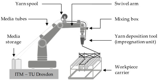
3. Production of Shaped TRC Elements Based on Adpative Molds
Adaptive formwork systems are suitable for the economical production of free-form concrete parts. They are based on multipoint tooling technology or pin-type tools. The basic principle is that a large number of pins or props are variably adjusted in height. This stepped representation of the desired geometry is smoothed with an elastic layer. A formwork of rubber or other elastic material is placed on the elastic layer, which is later filled with concrete and demolded. After completion, the same conformable form can be redesigned for a differently shaped panel [42][94]. Since textiles are thinner and more flexible than steel rebars, TRC elements can adopt curved shapes more easily, as well as achieve tighter or sharper curves (smaller curvature radii) compared with what is allowed by steel reinforcement. Reduced concrete cover and light weight makes TRC a more suitable option for adaptive molds, because their reduced thickness makes it easier to obtain curved shapes (thicker elements are harder to curve). Additionally, TRC reinforcement grids can be fabricated more efficiently than steel-reinforced reinforcement grids [42][94]. Preliminary studies are currently being conducted at ITA to investigate concrete penetration and positioning of the textiles in the free-form TRC panels prefabricated with adaptive molds. Figure 3 illustrates the casting of TRC panels on an adaptive mold. The coated and uncoated textiles with different textile architecture and materials are tested for their suitability with adaptive molds. The demonstrator TRC panels fabricated with an adaptive mold at ITA are depicted in Figure 3. An alternative way to use the adaptive mold is to apply concrete after deforming the mold into the desired shape. This is possible through the use of shotcrete (this method is already used with CNC-milled molds) and through the use of robotic techniques for placing textiles, such as automatic fiber placement and automatic tape placement, which are widely used in the composites industry. Commercially, adaptive formwork is already available from Adapa AS, Aalborg, Denmark. Computer-aided control means that the production of multicurved components requires less effort than with conventional formwork systems [43][95].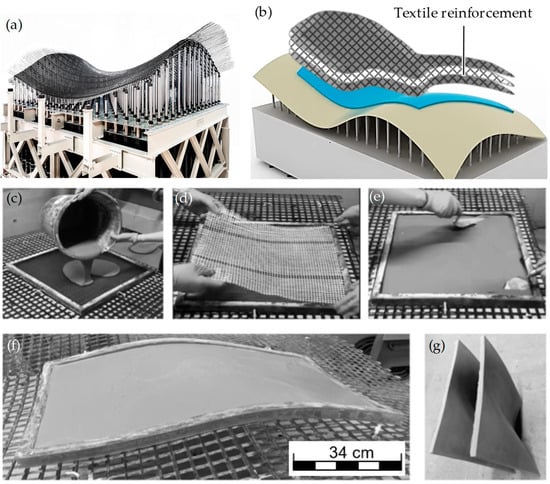
Figure 3. Precasting of TRC with adaptive mold at ITA: (a) industry-scale adaptive mold form ADAPA AS; (b) schematic; (c) filling silicon mold with first layer of concrete in flat position; (d) placement of textile reinforcement; (e) pouring second layer of concrete; (f) deforming on the adaptive mold; (g) precast TRC panels.
- -
-
Definition of design potentials and aesthetic trends in construction for TRC elements.
- -
-
Classification of building components with regard to form specifications and derivation of ideal textile architectures for the classified component groups.
- -
-
Fabrication of component-specific textile reinforcements.
- -
-
Shaping of TRC in the fresh state.
- -
-
In situ integration of insulating materials on the TRC panels in the precast plant.
- -
-
Integration of anchoring elements into the textile reinforcement.
- -
-
Design of a process chain for series production of functionally integrated curved TRC panels.
- -
-
Preparation of the implementation of a complete process chain for the form-flexible production of TRC components.
4. Textile Reinforcement for Additive Manufacturing of Concrete
Additive manufacturing methods have made great advancements in various industries in recent years, including the construction industry. Especially, digital fabrication with concrete (often called 3D concrete printing (3DCP)) has received a lot of interest in academia and industry alike, promising faster and safer fabrication of concrete elements and even whole buildings. While large advances have been made, many research challenges for 3DCP remain. Chief among them is the integration of reinforcement structures into the manufacturing process, since reinforcements are mandatory for nearly all structural applications. Various approaches to integrate reinforcements into 3DCP have been developed, researched, and classified, as presented by Mechtcherine et al. [44][96]. While most of the current approaches use steel-based reinforcements, as is common in the construction industry (e.g., [45][46][47][97,98,99]), some research into the usage of textile solutions has been performed. The simplest solution for the integration of textile reinforcements into 3DCP is the integration of randomly oriented short fibers into the printed concrete, as preformed, for example, by [48][49][100,101]. However, the strength increase that can be reached by this approach is limited. Another possibility is the integration of rovings or yarns into the printed concrete layers, as, for example, researched by [50][102]. This approach offers improved bending strength of the layers but does not improve the interlayer connection or strength. To improve this interlayer strength, the integration of (at least) two-dimensional textiles is necessary. These two-dimensional textiles are often grid-like structures (e.g., biaxial noncrimp fabrics as used in conventional TRC) and can be applied at various steps of the digital concrete production process. They can be applied as an initial reinforcement cage onto which the concrete is added (e.g., [51][52][103,104]), placed during the digital concrete production (e.g., [53][105]), or added as an additional reinforcement layer after digital concrete production is concluded (e.g., [54][55][106,107]). Two approaches for the integration of multidimensional textile reinforcements into 3DCP are presented in Figure 4 below. In both approaches, the textile is fixed in place prior to the additive concrete manufacturing process, and the concrete is added to the textile [56][108]. Differing from the approaches described above, the concrete can penetrate through the textile and encloses the textile within the concrete matrix. Initial trials into the approach presented in Figure 4a showed the same performance for TRC specimens produced by using 3DCP and using traditional TRC casting methods [57][58][109,110]. For the approach presented in Figure 4b, initial trials show that adhesion between a spacer fabric made from AR-glass and a printed concrete matrix is sufficient [59][60][61][111,112,113].3DCP is a highly topical research area offering interesting and relevant solutions to many of the challenges the construction industry faces today, especially regarding workplace safety and loss of workforce. Since the integration of a reinforcement is a key challenge for the widespread application of 3DCP, solutions to this challenge are highly relevant. Textile reinforcements are uniquely suited for the integration into 3DCP, since they offer high-performance reinforcement that only needs minimal concrete cover, while being lightweight and easy to handle. However, research into the integration of textile reinforcements in 3DCP is only beginning, and many promising research approaches (integration method, type of textile, etc.) and challenging questions (regarding material, processing, performance, etc.) remain.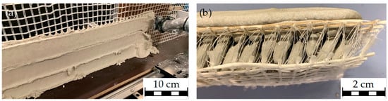 Figure 4. Two approaches for the textile reinforcement of 3D concrete printing: (a) printing though a two-dimensional, grid like textile; (b) specimen made by printing onto a three-dimensional spacer fabric.
5. Load-Path-Oriented Textile Reinforcement Using Tailored Fiber Placement
The technological developments in fiber-reinforced plastics (FRP) manufacturing offer great potential to be transferred to the processing of textile-reinforced concrete. The development of FRP opens up the potential for high strength, stiffness, and light weight of structural components. To achieve full performance, the anisotropic fibers need to be oriented to match the load being applied. In most cases, however, layered structures of unidirectional (UD) yarns, known as multiaxial laminates, are used for composite fabrication. This is mainly due to the availability of semifinished textile products (e.g., woven and nonwoven) and well-established numerical methods for the design of multiaxial laminates [62][114]. However, this leads to a significantly reduced component performance. Tailored fiber placement (TFP) is a new automated textile process for the production of reinforcing structures. TFP is an embroidery-based, tow-steering process that enables complete control over fiber placement and directionality in a composite preform. During the process, a reinforcing roving is stitched to a base material using numerical control. The results are highly engineered composite structures that take full advantage of the anisotropic nature of fiber reinforcement. This process allows the consistent transfer of calculated locally optimum fiber quantities and orientations into fiber preforms. TFP has become well-established in the automotive or aerospace industries, but it still is not a common solution for the construction industry. However, recently, there has been an in-creased used of this technology in the building and architecture sector, and some examples of experimental or academic nature are presented below. In the case of concrete precast panels, the TFP machine lays the rovings on top of a substrate that can be permeable (i.e., an open fabric with gaps through which fresh concrete can flow and thus embed the fibers properly) or removable (i.e., a closed fabric that must be removed to allow concrete to fully embed the carbon fibers). An example of load-path-oriented advanced textile reinforcements is shown in Figure 5. To increase the productivity of TFP, a new process called Tailored Fiber Placement high-Volume TFP (hV) was developed by Hightex Verstärkungsstrukturen GmbH, Klipphausen, Germany, allowing placement of up to 2000 g/h of 50K rovings.Finally, one of the main limitations of TFP elements is their characteristic flat (2D) fabrication state, which remains in their final shape. In order to eliminate this constraint and produce freeform elements, research has been conducted at the ICD and ITKE institutes of the University of Stuttgart, in which “technical” carbon fibers or “natural” flax fibers (embedded on oil-based or bio-based epoxy resins) are used to produce nonconcrete structures with 3D or “2.5 D” geometries. Examples of this are the “Tailoring Self-Formation” [63][115], “FlexFlax Stool” [64][116], and “Biomimetic NFRP Stools” [65][117] projects. In most of these projects, the density and direction of the rovings is adjusted to the naturally occurring load paths (in order to achieve structural efficiency or to help generate the desired final shape of the element (due to localized stiffness variations)) [63][115]. The development of novel load-path-oriented structures is linked to issues of manufacturability, product-related sustainability assessment, and further development of the composite material itself. New and innovative design strategies enable a completely different design methodology, reduce resource and energy consumption, and at the same time ensure high serviceability, load-bearing safety, and durability. Further research on the aforementioned aspects needs to be performed for the tailored fiber placement technology, thereby establishing TFP as a novel manufacturing technique for textile reinforcements used in building panels.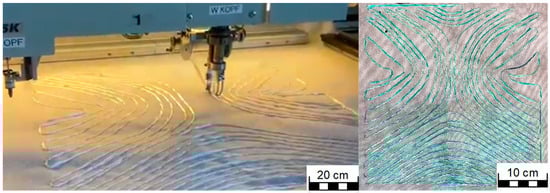 Figure 5.Load-path-oriented advanced textile reinforcement for freeform concrete panels using tailored fiber placement (TFP).