Your browser does not fully support modern features. Please upgrade for a smoother experience.
Please note this is a comparison between Version 2 by Jason Zhu and Version 1 by Kritika Deepak.
There has been significant attention given to the electrification of transportation due to concerns about fossil fuel depletion and environmental pollution. Conventional drive systems typically include a clutch, reduction gear, and mechanical differential, which results in power loss, noise, vibration, and additional maintenance. However, in-wheel motor drive technology eliminates the need for these components, providing benefits such as higher system efficiency, improved wheel control, and increased passenger comfort.
- in-wheel motors
- axial flux motors
- outer-rotor PMSM motors
1. Introduction
Over the past few decades, there has been widespread attention given to the issues of energy crises and environmental pollution. The global community has recognized the urgency of conserving energy and reducing emissions, as indicated by the research in [1][2]. Electrification has emerged as an alternative solution for various industrial applications, particularly in the realm of transportation, where electric vehicles have shown promise. Thanks to advances in high-performance electric motors and power electronics, electric and hybrid electric vehicles (EVs/HEVs) are being developed and studied as a substitute for conventional internal combustion engines (ICE) automobiles [3]. The Tesla Model 3, Renault Zoe, Volkswagen ID3, and Volkswagen ID4 are currently the most popular EVs in the european market [4][5][6][7]. However, the conventional central-motor drive system in EV/HEV involves linking the propulsion motor to the wheels via a chain of mechanical transmission components [8][9]. Unfortunately, this mechanical transmission setup leads to increased weight and higher maintenance costs [10]. Alternatively, an in-wheel motor (IWM) could be used to directly power the wheels without the use of mechanical transmission. Placing the motor inside the wheel rim allows for the speed and torque output of the motor to be directly transmitted to the wheel. Consequently, IWMs operate at lower speeds but with higher torque when compared to central-motor drives. This method provides numerous benefits, including increased space for passengers and batteries, as well as greater control flexibility through independent wheel control [11].
Over a hundred years ago, in 1900, the first-ever IWM driven automobile was created by Lohner–Porsche Electromobile [12]. This vehicle was propelled by two IWMs, which were powered by a forty-four cell 80-volt lead battery [13]. Later, Porsche also introduced the first functional hybrid car, using a combustion engine to drive the generator and supply power to the wheel hub motor. This car failed over the years as it weighed almost two tonnes [12]. Electric cars and gasoline-powered cars were in significant competition for a period of time. Nonetheless, the introduction of Henry Ford’s Model T in 1908 led to a shift in favor of gasoline-powered vehicles, ultimately resulting in greater affordability at a larger scale. In the following years, electric vehicles were outperformed by ICE vehicles.
The contemporary fascination with electric vehicles can be traced back to the release of the Toyota Prius in 1997, which was the world’s first mass-produced hybrid electric vehicle. This event sparked interest in modern electric vehicles in the automobile market. Moreover, the US Department of Energy states that electric vehicles are highly energy efficient as they convert more than 77% of electrical energy into power that drives the wheels. In stark contrast, gasoline-powered vehicles convert only 11% to 37% [3] of the energy stored in gasoline into kinetic power. Additionally, the rising global awareness and concern for environmental impact of combustion vehicles fueled by oil is drawing consumers to go electric.
2. Motor Topologies for IWMs
2.1. Radial Flux Motors
2.1.1. Topologies of Radial Flux Motors in IWMs
Permanent Magnet Synchronous Motors
The outer-rotor PMSM (OR-PMSMs) with neodymium PMs are a conventional choice of motor designers both in research and industrial sector for IWM-drive applications due to their high torque density. Fractional slot-concentrated winding is the preferableoption to accommodate an in-wheel installation, and opting for a high pole count results in a slimmer iron yoke design, ultimately reducing both weight and size [14][15]. The advantages of concentrated windings, such as enhanced fault tolerance and streamlined manufacturing, are well-documented in the literature [16][17]. Additionally, incorporating a multi-phase design can further improve fault tolerance. Certain OR-PMSM models include sub-motors to increase fault tolerance, and various techniques have been implemented to mitigate parasitic effects, such as eddy currents and NVH [18][19].Switched Reluctance Motor
The outer-rotor switched reluctance machine (OR-SRM) is a potential non-PM option for IWM-DEVs [20]. While it offers low cost, compact size, and a robust structure, due to the high magnetic saturation present in both the stator and rotor steel, the flux characteristics of the machine are non-linear [21]. As a result, the machine’s efficiency is reduced and its torque performance is inferior to PMSM [22]. In [23] proposed a motor that combines the advantage of multiple teeth per stator pole and more rotor poles than stator teeth to achieve the purpose of enhancing the specific torque. The structure of two teeth can improve the output torque. Increasing the number of rotor poles results in a larger slot area for winding and allows a larger excitation current. However, the OR-SRM produces high pulsating torque, vibration, and noise, making it less desirable for IWM-drive applications. Researchers have employed multiphysics modeling and improved control methods to address these NVH issues [24][25].Synchronous Reluctance Motor
Outer-rotor synchronous reluctance motors (OR-SynRM) are an under-explored class of motors for use as IWMs. Their torque ripple is smaller and they are quieter than OR-SRM. They also have higher efficiency than OR-SRM [26]. Figure 7 illustrates the topology of a OR-SynRM. Unlike OR-SRM, OR-SynRM can utilize the same stator as the PMSM motor. A sizing and design procedure of OR-SynRM is presented in [27] to optimize the flux barrier shape and rotor and stator size. The study took into account the structural analysis to ensure the rotor with flux barriers can withstand the stress at higher speeds. A PM-assisted OR-SynRM is presented in [28] for IWM applications. A novel dual-rotor SynRM [29] is designed and compared with a single rotor counterpart. The dual rotor motor showed higher power density and lower torque ripple when compared to a single rotor. The above mentioned research developed OR-SynRM with maximum power 5 kW, hence more research investigation is required to develop high power OR-SynRM for IWM-DEVs.Induction Motor
While PM-based motors are currently the preferred choice for traction applications, induction motors (IMs) have historically been favored for industrial applications due to their robustness and low-cost and as the price of rare-earth materials has risen sharply, there have been efforts to develop IMs for use in electric traction applications [22][30]. Induction motors with distributed windings are the most prevalent, but their winding configuration is not favored due to the larger overall size of the machine and reduced magnetic core utilization, which is a huge limitation for IWM application [31]. In [32], a stator design with auxiliary slots and variable turns per coil is utilized to mitigate the spatial harmonics of the MMF. However, this approach entails a complex manufacturing process. In [33][34], the toroidal winding is proposed as a solution for reducing end-winding length in OR-IM. This enables the use of a startup strategy that entails a brief period of high current, resulting in lower power consumption. However, toroidal windings have some drawbacks: the winding process is complex and labor-intensive, which can lead to increased manufacturing costs and longer lead times and high leakage inductance, which can result in increased power loss and reduced motor performance [35].2.1.2. Industrial State of the Art in Radial Flux Motors for IWMs
The industrial sector is dominated by outer-rotor PMSM motors for IWM applications. This is due to the high torque density owing to the rare earth PMs used in them. The trend shows that intensive research is required for torque dense motors without using RE magnets to compete in the industry. Elaphe has developed four IWM in their portfolio: S400, M700, M1100, and L1500. S400 is designed for light weight EV and HEVs and can operate at 48 V and 100 V DC link voltage providing 400 N m peak torque and maximum speed of 750 RPM and 1565 RPM at 48 V and 100 V, respectively. Elaphe’s M700 is suitable for medium weight passenger cars with peak torque 700 Nm and maximum speed 1500 RPM. M1100 provides peak torque 1100 Nm and maximum speed 1160 RPM. The most powerful in the range is L1500, with a peak torque of 1500 Nm and peak power of 110 kW . Lordstown Motor uses Elaphe’s L1500 in their all-electric pickup truck, making it the first commercially available EV driven with IWM [36][37]. All the motors are liquid cooled and utilizes NdFeB magnets for high torque density. The motor topology is outer-rotor PMSM [38].2.2. Axial Flux Motors
Radial flux machines have been more popular since the beginning of electric motors’ origin, and overshadowed the axial flux machines. This is partly because axial flux machines are more complicated to manufacture and operate. The intense magnetic force along the axis between the stator and rotor can cause the rotor discs to bend, and the production process can be difficult due to factors such as slotted stator lamination, high expenses, and challenges in assembling the various parts [39]. However, recent trends have shown that the features of axial motors are extremely favourable for IWM-DEVs, such as compact axial length, high torque density and flexible structure [40]. Despite extensive research on the topologies of axial flux machines, there are still gaps in their practical use and certain aspects of their analysis and design that need further exploration. To mitigate uncertainties related to rare-earth materials, there is ongoing research on developing non-rare-earth AFMs for IWM-DEVs. An axial flux switched-reluctance motor (AF-SRM) has beendeveloped for use in IWM-DEVs. This motor has a higher torque density than its radial flux counterpart. Additionally, the inherent problem of high pulsating torque can be addressed by using a double-rotor structure. AFMs and RFMs require different materials due to the difference in direction of the flux. Non-oriented grain electric steel and amorphous soft material are commonly used in AFMs [41]. The axial flux motors has the following advantages:-
Compact structure, especially short axial sizes which is ideal for IMW technology;
-
Small stator core volume, therefore reduced stator core loss;
-
Low weight;
-
High torque density;
-
Manufacturing and assembly problems due to complicated structure;
- High power density;
-
Higher cost;
- Flexible and modular structure; motors can be stacked axially to increase the torque and power;
-
Prone to non-uniform airgap due to strong axial magnetic forces between stator and rotor.Small end-winding hence lower copper losses.
2.2.1. Topologies of Axial Flux Motors
Figure 1 shows the classification of axial flux-motor topologies based on the rotor and stator axial placement. According to the number of stator and rotor used and their relative position in the motor structure, the axial flux motors are categorized as single-stator single-rotor (SSSR), single-stator double-rotor (SSDR), double-stator single-rotor (DSSR), and multi-stator multi-rotor (MSMR). Like radial flux motors, the rotor of axial flux motors can either be permanent magnet (PM-based) or induction motors.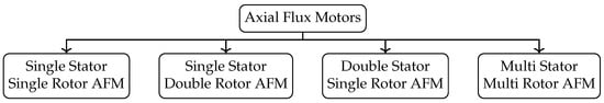
Figure 1. Axial Flux Motors classification.
Single-Stator Single-Rotor (SSSR)
The single-stator single-rotor (SSSR) configuration is the most basic structure of AFMs. Due to their compact size and high torque capacity, SSSR-type AFMs are widely utilized in the servo drive, gearless elevators, and transportation industries [42]. However, the unbalanced axial force between the stator and rotor can cause structural deformation, generate vibration noise, and shorten the motor’s lifespan [43]. To achieve maximum rotational torque while minimizing axial force, several techniques have been proposed, including adjusting the portions of stator winding currents, utilizing complex bearing arrangements, using a thicker rotor disc, and implementing a current shifting angle [44].Single-Stator Double-Rotor (SSDR)
AFM motors of the single-stator double-rotor (SSDR) type, which feature a slotted or slotless stator positioned between two rotors, exhibit excellent symmetry that effectively cancels out unbalanced axial forces. As a result, the motor’s vibration and lifespan can be improved over its lifecycle. Slotless machines are particularly advantageous because their end windings are shorter, resulting in lower copper loss and better heat dissipation. In addition, leakage and mutual inductance are reduced in slotless configurations, resulting in the elimination of slot effects such as flux ripple, cogging torque, high-frequency rotor loss, and stator teeth. This configuration is highly suitable for IWMs [45]. A SSDR type axial flux induction motor is designed in [46] to eliminate the magnetic axial force between the rotor and stator. The rotor design was optimized to reduce the torque ripple by introducing the skewing and rotational displacement of rotors, which also increases the power factor of the motor as well.Double-Stator Single-Rotor (DSSR)
In double-stator single-rotor (DSSR) AFM motors, the rotor is sandwiched between two stators. The permanent magnet (PM) can be positioned on the surface or inside the rotor. Inserting the PM inside the rotor provides better protection against shock and corrosion compared to the surface-mounted PM structure [47]. The power density of the interior permanent magnet (IPM) structure is lower than that of the surface-mounted structure due to the need for a thicker rotor disc. Additionally, the leakage flux of PM ends and armature reactions are higher in the interior design due to the PMs being surrounded by ferromagnetic material. A DSSR can have either a slotted stator (SS type) or a slotless stator (NS type) configuration, with the rotor situated between the two stators. A DSSR-type axial flux switched-reluctance motor was used by [48] for IWM applications. The axial flux switched-reluctance motor has the advantage of magnetic force equalization in terms of stator balance compared SSSR, the existence of two stators results in two air gaps and a reduced peak inductance, leading to a lower power density.Multi-Stator Multi-Rotor (MSMR)
MSMRs, also referred to as multi-stage AFPM machines, can be built using either DSSR or SSDR configurations. The MSMR-type AFPM motors consist of N stators and (N+1) rotors, enabling them to achieve higher torque and power density without an increase in motor diameter. These motors are well-suited for high-torque applications, such as ship propulsion. The stator windings of AFPM and RFPM machines can be connected in either parallel or series. In a multi-stage configuration, the torque and power density are improved without increasing the diameter of the machine. Compared to RFPM machines, multi-stage AFPM machines are easier to assemble due to their planar air gap [49].2.2.2. Industrial State of the Art in Axial Flux Motors
YASA has created motors with a yokeless and segmented armature design. YASA 750R motor can produce a peak power density of >5 kW/kg, peak torque density >75 Nm/L with peak efficiency of >95% at its highest point [50]. The YASA design eliminates the torque ripple caused by stator slotting and reduces the mass of the motor. However, due to a longer airgap length, the winding inductance is lower, resulting in a reduced flux-weakening capability [51]. Avid Technologies, now acquired by Turntide technologies [52], produces highly efficient AFM for DC link operating voltage up to 800 V. Magnax provides an axial flux motor with high peak power density of 12.5 [kW/kg]. Emrax provides axial flux motors with 100–1000 Nm for both automotive and aerospace applications. Figure 2 shows a power trend comparison of commercially available IWMs for EVs. It can be noticed that some central-motor drives, such as the Porsche Taycan Turbo S, can provide an extremely high over-boost power of 560 kW but at the cost of high mass ( 76 kg) [53]. A general trend of high power with lower mass can be seen in axial flux IWMs. Motors such as Magnax AXF275, Turntide, and EMRAX motors [54][55][56] have also claimed to have peak efficiency over 95% with high power densities. Because of their shorter magnetic path, AFMs can produced a higher torque than RFMs [57]. IWMS have stricter requirements in terms of space as they need to fit in the wheel hub, hence their outer diameter and axial length is limited, affecting their torque/power capabilities directly. Research focused on the optimization of the motor geometrical parameters and cooling system to increase the torque capability and minimize the losses needs more attention.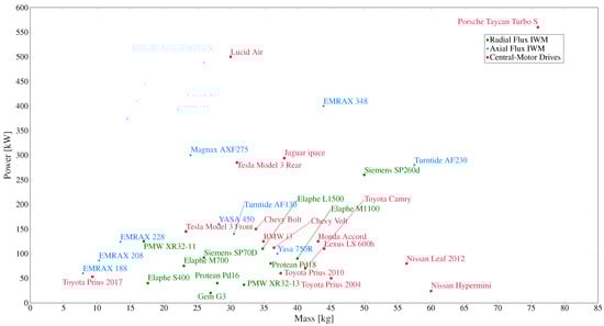
Figure 2. Power vs. mass trend of commercially available radial flux IWM, axial flux IWM, and central-motor drives for EVs.
3. Integrated Power Electronics in IWMs
As a result of their significant potential advantages, machine manufacturers are actively involved in developing and producing IMDs. Substituting inefficient motors, improving power density, reducing losses, and reduced prices when compared to separate motor and drive solutions are among the most important advantages of IMDs. According to [58], over the last decade, technological breakthroughs have resulted in the development of strong electronic components capable of withstanding the extreme environments required by certain techniques of integration. The integrated solution has minimized electromagnetic interference (EMI) and winding voltage surge induced by the surge impedence imbalance between the cables and windings by eliminating individual casings and extensive cable runs [59][60]. The volume of the whole drive can be reduced by 10–20% [61] and system costs by 20–40% [62]. Integration of an IWM with an inverter can reduce long connecting wires and additional housing, resulting in increased power/torque density [63]. According to [64] the latest advancements of wide bandgap semiconductors has improved the power density and ability to withstand higher temperature for elongated time of power electronics modules. Therefore, the integrated motor drive system is extremely appealing for EVs with very demanding electric drive volume, mass, and efficiency criteria. An integrated and modular drive topology is proposed using SSDR yokeless and segmented (YASA) AFPM in [65]. GaN switches are used to reduce the size of the converter. To prevent converter overheating, the stator and power converter components are thermally isolated. Protean has implemented an integrated motor drive technique for its in-wheel system. High fault tolerance is achieved in the Protean IWM system by utilizing four sub-motors and four sub-inverters. Only two DC connections are required for the power supply because the inverter is integrated with the motor. This design reduces the efficiency losses associated with the use of connecting cables between the motor and inverter. Nonetheless, there are concerns to be addressed during the development of integrated motor drives. The drive circuits must be capable of surviving harsh on-road conditions, such as high/low temperatures, dirt, water, and vibration, since they are sealed inside the wheel.4. Cooling of IWMs
4.1. Air Cooling
Air cooling, which is the most fundamental method of cooling motors and is usually used to cool motors with a low heat density, can be accomplished through both natural air cooling on the outer surface and forced air cooling within the motor. A 25 kW air-cooled IMW is proposed in [66] with grooves on the outer surface to increase the cooling surface area exposed to wind. It is concluded that the densely arranged grooves in the same direction as the air flow direction provide the best cooling performance. The study was conducted at a continuous rated operation of 1250 RPM at 40 A and 76.5 Nm, and peak performance is not mentioned in the study. [67] designed and verified an air-cooled YASA AFPM motor. To enhance heat dissipation and power density, the novel cooling system utilized aluminum heat-spreading components on each armature section. The heat-spreading components offered a low-resistance heat channel to the surrounding air.4.2. Oil Cooling
The oil-cooling method uses a pump to circulate oil as a cooling medium both inside and outside the motor, effectively reducing its temperature. Compared to air, oil has a higher convection coefficient, resulting in superior thermal performance. Additionally, oil can be sprayed directly on the windings for better heat dissipation. To investigate the effect of oil spray cooling on thermal dissipation for higher power output, an oil-cooling system is used for a 35 k W IWM. The cooling path for oil is provided by implementing a hollow shaft cooling channel suitable for IMW [68]. The shape of the oil cooling channel in the hollow shaft is optimized in [69]. The coil temperature in the optimized motor was reported to be reduced by maximum of 13.5 ∘C. [70] used a multi-objective genetic-algorithm optimization to optimize the cooling channel for oil. In high-torque motors, the current density often exceeds 20 A/mm2 which results in high copper losses. In general, copper losses account for the highest percentage of losses in the motor. The source of copper is in the winding, hence a direct cooling for the winding can improve the motor efficiency. In [71], an in-slot oil cooling for a PMSM is designed and verified for continuous operation with 25 A/mm2 and 35 A /mm2 for 30-s peak operation. Reference [72] reported that with the direct oil cooling for the end winding in AFPM, the oil extracted about 2.8 times more heat compared to the water jacket cooling and effectively double the torque and power density of AFPM as compared to indirect water cooling. However, this method is challenging to implement in outer rotor topology. In [73], a novel winding embedded liquid cooling for slotless motors is proposed. The results showed that proposed method can increase the continuous current density by 35% as compared to in-slot water cooling.4.3. Water Cooling
The most prominent cooling method for commercial motors, particularly in electric traction applications, is liquid jacket cooling. Heat is expelled by a liquid coolant predominantly by convective heat transfer in the jacket. In most cases, the coolant is water. Glycol is often added to water to decrease the freezing point of the mixture. It is important to use the lowest concentration of glycol necessary to meet the freeze protection requirements because as the concentration of glycol in the solution rises, the effectiveness of the heat transfer fluid drops. The performance of a coolant jacket has been investigated in numerous studies with regard to the channel dimensions, cross-section shape, and flow rate. A comparison of spiral and axial type cooling water jackets has been investigated in [74]. The authors recommend the use of an axial water jacket due to its higher convective heat transfer coefficient compared to a spiral type water jacket. It should be noted, however, that axial water jackets have a more severe loss in pressure than spiral water jackets for the same amount of heat transfer area [75]. In [76] investigated the effect of flow-rate of the cooling water to optimize the electromagnetic performance of the motor. Based on this analysis, the parameters of the water channel structure are optimized with the suggested chaotic-mapping ant colony algorithm using the metropolis criteria to improve the heat dissipating efficiency of the cooling system. After optimization, an average increase of 23.57% in the convection heat transfer coefficient (CHTC), a reduction in the maximum stator temperature from 95.47∘C to 82.73 ∘C, and a 14.26% reduction in the peak temperature of the PM are observed. These improvements comprehensively reduce the risk demagnetization in the PM.5. Control Methods Used for IWMs and IWM Driven EVs
5.1. Control of the IWMs
5.1.1. Field Oriented Control (FOC)
FOC is a popular vector-control technique that is commonly used for electric motor drives, particularly for PMSMs [77]. Direct and indirect field-oriented control (DFOC/IFOC) are two approaches to implement FOC for electric motor drives. The main difference between these two methods lies in how the motor current and voltage signals are controlled. In direct FOC, the stator current components in the d-q reference frame are directly controlled by the voltage components in the same reference frame. This is achieved by using a PI controller to regulate the error between the desired and actual stator current and voltage components. Direct FOC is often used in high-performance applications where fast and accurate torque control is required [78]. In contrast, indirect FOC separates the control of the motor’s magnetic field and torque by using a separate controller for each component. The magnetic field is controlled indirectly by regulating the stator current in the d-axis, while the torque is controlled by regulating the stator current in the q-axis [79]. Indirect FOC is simpler to implement than direct FOC and is commonly used in low-to-medium performance applications. Direct FOC provides faster and more accurate torque control, but requires more complex algorithms and hardware, while indirect FOC is simpler to implement but may not be as precise in some high-performance applications. FOC is renowned for its excellent transient response. Figure 3 shows the operating principle of FOC for speed control in PMSM. The principles for FOC are the same whether the PMSM has an inner rotor or outer rotor. FOC for AFPM is implemented using space vector modulation (SVM) technique in [80][81] for both no-load and with load torque conditions.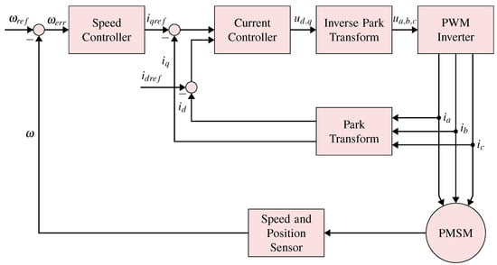
Figure 3. Field oriented control block diagram for speed control in PMSM.
5.1.2. Direct Torque Control (DTC)
DTC is simpler in structure than FOC and works by directly controlling the voltage and frequency applied to the motor based on the desired torque and speed. All calculations are performed in the stator reference frame since precise rotor position information is not required in these systems, except during start-up of the PMSMs. The computational capabilities needed for the controllers are relatively low. These types of systems have superior dynamic features, react promptly to load variations, and are less influenced by alterations in motor properties and interferences. Nevertheless, their steady-state operation has high ripple levels of the stator current, flux linkage, and torque, especially at low speeds, which greatly restricts their usage for high-precision drives [82]. Ref. [83] compares the efficiency and performance of IM used in EVs using two different control methods: IFOC and DTC. The study shows that compared to the IFOC, the DTC approach offers benefits in terms of speed tracking and energy consumption. In [84] the implementation of DTC for controlling AFPM led to a reduction in torque ripples compared to the FOC method.5.1.3. Model Predictive Control (MPC)
The use of model predictive control (MPC) has become increasingly popular due to advancements in microprocessors, enabling faster and more powerful computing. MPC offers advantages over conventional feedback control schemes, particularly when rapid dynamic response is necessary. It is a versatile control method that can be applied to various systems and is capable of accommodating constraints and non-linearities. MPC is also applicable in multi-variable cases and is easy to implement. Essentially, the MPC method involves using a system model to predict the future behavior of controlled variables, which is then utilized by the controller to determine the optimal actuation based on an optimization criterion. Predictive control offers the advantage of faster transient responses without the need for a cascaded structure that is usually employed in linear control schemes. However, one major hurdle in using MPC is the necessity for an accurate model, drive parameters, and increased sampling periods due to the large number of computations required.5.2. Control of Vehicle with IWMs: Torque Vectoring and Torque Distribution
IWM-DEVs offer several advantages, such as an independently controllable four-wheel torque, high energy-utilization rate, and fast motor response speed. The precise control of applied driving and braking torque also enables the use of advanced control methods, such as energy-efficiency control allocation (EECA) algorithms and electric stability control (ESC) based on the coordinated control of driving motors to improve the system performance [85]. However, as an over-actuated system, the control of IWM-DEVs is critical for achieving optimal performance, as the system has more actuators than degrees of freedom. The IWM-DEV’s nonlinear dynamics and strong system coupling add to the complexity of the control problem [86]. Disadvantages of independent motor control [86]:-
Non-linearity in the vehicle dynamics due to the coupling of longitudinal, lateral, and yaw dynamics, as well as the non-linear tire longitudinal and lateral characteristics;
-
The issue of over-actuation occurs due to the fact that there are four control inputs (torques on four wheels) which exceed the number of states requiring control. As a result, it is necessary to allocate torque based on specified objectives.
-
Active front steering (AFS) control: AFS offers an electronically controlled superimposition of an angle to the steering wheel angle, allowing for a continuous and driving-situation dependent adaptation of the steering characteristics. This additional degree of freedom enables the optimization of steering comfort, effort, and dynamics [90][91][92].
References
- Hawkins, T.R.; Gausen, O.M.; Strømman, A.H. Environmental impacts of hybrid and electric vehicles—A review. Int. J. Life Cycle Assess. 2012, 17, 997–1014.
- Pg Abas, A.E.; Yong, J.; Mahlia, T.M.; Hannan, M.A. Techno-economic analysis and environmental impact of electric vehicle. IEEE Access 2019, 7, 98565–98578.
- Albatayneh, A.; Assaf, M.N.; Alterman, D.; Jaradat, M. Comparison of the Overall Energy Efficiency for Internal Combustion Engine Vehicles and Electric Vehicles. Environ. Clim. Technol. 2020, 24, 669–680.
- Krings, A.; Monissen, C. Review and trends in electric traction motors for battery electric and hybrid vehicles. In Proceedings of the 2020 International Conference on Electrical Machines, ICEM 2020, Gothenburg, Sweden, 23–26 August 2020; pp. 1807–1813.
- Hecht, C.; Spreuer, K.G.; Figgener, J.; Sauer, D.U. Market Review and Technical Properties of Electric Vehicles in Germany. Vehicles 2022, 4, 903–916.
- Burress, T.A.; Campbell, S.L.; Coomer, C.; Ayers, C.W.; Wereszczak, A.A.; Cunningham, J.P.; Marlino, L.D.; Seiber, L.E.; Lin, H.T. Evaluation of the 2010 Toyota Prius Hybrid Synergy Drive System; Technical Report; Oak Ridge National Lab: Oak Rigde, TN, USA, 2011.
- Wellings, J.; Greenwood, D.; Coles, S.R. Understanding the Future Impacts of Electric Vehicles—An Analysis of Multiple Factors That Influence the Market. Vehicles 2021, 3, 851–871.
- Sanguesa, J.A.; Torres-Sanz, V.; Garrido, P.; Martinez, F.J.; Marquez-Barja, J.M. A Review on Electric Vehicles: Technologies and Challenges. Smart Cities 2021, 4, 372–404.
- Mierlo, J.V.; Berecibar, M.; Baghdadi, M.E.; De Cauwer, C.; Messagie, M.; Coosemans, T.; Jacobs, V.A.; Hegazy, O. Beyond the State of the Art of Electric Vehicles: A Fact-Based Paper of the Current and Prospective Electric Vehicle Technologies. World Electr. Veh. J. 2021, 12, 20.
- Yong, J.Y.; Ramachandaramurthy, V.K.; Tan, K.M.; Mithulananthan, N. A review on the state-of-the-art technologies of electric vehicle, its impacts and prospects. Renew. Sustain. Energy Rev. 2015, 49, 365–385.
- Zhao, Y.; Zhang, Y.; Zhao, Y. Stability control system for four-in-wheel-motor drive electric vehicle. In Proceedings of the 6th International Conference on Fuzzy Systems and Knowledge Discovery, FSKD 2009, Tianjin, China, 14–16 August 2009; Volume 4, pp. 171–175.
- The History of Porsche Begins Electrically—Porsche Newsroom. Available online: https://newsroom.porsche.com/en/products/taycan/history-18563.html (accessed on 21 February 2023).
- 1900 Lohner-Porsche Mixte Voiturette—Images, Specifications and Information. Available online: https://www.ultimatecarpage.com/car/3456/Lohner-Porsche-Mixte-Voiturette.html (accessed on 24 February 2023).
- Wang, X.; Zhang, Z.; Gao, P.; Lu, H.; He, X. Design and Simulation Analysis of a Novel Outer Rotor IPM Motor Used in Electric Vehicles. In Proceedings of the 13th World Congress on Intelligent Control and Automation (WCICA), Changsha, China, 4–8 July 2018.
- Fan, Y.; Chen, S.; Tan, C.; Cheng, M. Design and investigation of a new outer-rotor IPM motor for EV and HEV in-wheel propulsion. In Proceedings of the 19th International Conference on Electrical Machines and Systems (ICEMS), Chiba, Japan, 13–16 November 2016.
- Ishii, S.; Hasegawa, Y.; Nakamura, K.; Ichinokura, O. Characteristics of Novel Flux Barrier Type Outer Rotor IPM Motor with Rare-earth and Ferrite Magnets. In Proceedings of the 2012 International Conference on Renewable Energy Research and Applications (ICRERA), Nagasaki, Japan, 11–14 November 2012.
- Fornasiero, E.; Morandin, M.; Carraro, E.; Bianchi, N.; Bolognani, S. Outer Rotor IPM Generator with Wide Constant Power Region for Automotive Applications. In Proceedings of the 2014 IEEE Transportation Electrification Conference and Expo (ITEC), Dearborn, MI, USA, 15–18 June 2014.
- Gong, J.; Zhao, B.; Huang, Y.; Semail, E.; Nguyen, N.K. Quantitative Comparisons of Outer-Rotor Permanent Magnet Machines of Different Structures/Phases for In-Wheel Electrical Vehicle Application. Energies 2022, 15, 6688.
- Yao, Y.; Liu, C.; Lee, C.H. Quantitative comparisons of six-phase outer-rotor permanent-magnet brushless machines for electric vehicles. Energies 2018, 11, 2141.
- Labak, A.; Kar, N.C. Outer rotor switched reluctance motor design for in-wheel drive of electric bus applications. In Proceedings of the 2012 20th International Conference on Electrical Machines, ICEM 2012, Marseille, France, 2–5 September 2012; pp. 418–423.
- Yaling, W.; Yanliang, X.; Yufang, W.; Yun, Z. Outer-rotor switched reluctance motor and its control system used in electric vehicles. In Proceedings of the 2011 International Conference on Electrical Machines and Systems, ICEMS 2011, Beijing, China, 20–23 August 2011.
- Boldea, I.; Tutelea, L.N.; Parsa, L.; Dorrell, D. Automotive electric propulsion systems with reduced or no permanent magnets: An overview. IEEE Trans. Ind. Electron. 2014, 61, 5696–5711.
- Zhu, J.; Cheng, K.W.E.; Xue, X.; Zou, Y. Design of a New Enhanced Torque In-Wheel Switched Reluctance Motor with Divided Teeth for Electric Vehicles. IEEE Trans. Magn. 2017, 53, 2703849.
- Qin, Y.; He, C.; Shao, X.; Du, H.; Xiang, C.; Dong, M. Vibration mitigation for in-wheel switched reluctance motor driven electric vehicle with dynamic vibration absorbing structures. J. Sound Vib. 2018, 419, 249–267.
- Zhu, Y.; Zhao, C.; Zhang, J.; Gong, Z. Vibration control for electric vehicles with in-wheel switched reluctance motor drive system. IEEE Access 2020, 8, 7205–7216.
- Jurca, F.N.; Martis, C. Analysis of outer rotor synchronous reluctance motor for low-speed applications. In Proceedings of the International Conference on Electical Drives and Power Electronics, Dubrovnik, Croatia, 4–6 October 2017; pp. 242–247.
- Aghazadeh, H.; Afjei, E.; Siadatan, A. Sizing and detailed design procedure of external rotor synchronous reluctance machine. IET Electr. Power Appl. 2019, 13, 1105–1113.
- Bozkurt, A.; Baba, A.F.; Oner, Y. Design of Outer-Rotor Permanent-Magnet-Assisted Synchronous Reluctance Motor for Electric Vehicles. Energies 2021, 14, 3739.
- Al-ani, M. Multi-physics design and analyses of dual rotor synchronous reluctance machine. eTransportation 2021, 8, 100113.
- Klima, P.; Rura, D.; Vitek, O. Analysis and Reduction of Eddy Current Losses in High-Speed Solid Outer Rotor Induction Machine. In Proceedings of the 2022 International Conference on Electrical Machines, ICEM 2022, Valencia, Spain, 5–8 September 2022; pp. 1022–1026.
- Virlan, B.; Benelghali, S.; Simion, A.; Livadaru, L.; Outbib, R.; Munteanu, A. Induction motor with outer rotor and ring stator winding for Multispeed applications. IEEE Trans. Energy Convers. 2013, 28, 999–1007.
- Rezazadeh, G.; Tahami, F.; Capolino, G.A.; Nasiri-Gheidari, Z.; Henao, H.; Sahebazamani, M. Improved Design of an Outer Rotor Six-Phase Induction Motor With Variable Turn Pseudo-Concentrated Windings. IEEE Trans. Energy Convers. 2022, 37, 1020–1029.
- Virlan, B.; Benelghali, S.; Munteanu, A.; Simion, A.; Outbib, R. Multi-speed induction motor for direct drive applications. In Proceedings of the 2012 20th International Conference on Electrical Machines, ICEM 2012, Marseille, France, 2–5 September 2012; pp. 1928–1934.
- Livadaru, L.; Munteanu, A.; Simion, A.; Cantemir, C.G. Design and finite element analysis of high-density torque induction motor for traction applications. In Proceedings of the 2015 9th International Symposium on Advanced Topics in Electrical Engineering, ATEE 2015, Bucharest, Romania, 7–9 May 2015; pp. 211–214.
- Virlan, B.; Simion, A.; Livadaru, L.; Benelghali, S.; Outbib, R. Analysis of a three phase induction motor with outer rotor for multi-speed applications. In Proceedings of the 2012 20th International Conference on Electrical Machines, ICEM 2012, Marseille, France, 2–5 September 2012; pp. 411–417.
- Endurance—Lordstown Motors. Available online: https://www.lordstownmotors.com/pages/endurance (accessed on 9 February 2023).
- Lordstown “Endurance”—The World’s First All-Electric Commercial Pickup Truck—Elaphe. Available online: https://in-wheel.com/en/news/lordstown-endurance-the-worlds-first-all-electric-commercial-pickup-truck/ (accessed on 1 January 2020).
- Elaphe Direct-Drive in-Wheel Motors. Available online: https://in-wheel.com/en/solutions-2/direct-drive-in-wheel-motors/ (accessed on 9 February 2023).
- Deng, W.; Zuo, S. Axial force and vibroacoustic analysis of external-rotor axial-flux motors. IEEE Trans. Ind. Electron. 2018, 65, 2018–2030.
- Hattori, A.; Noguchi, T.; Kamiyama, H. High-Torque Density Design of Small Motors for Automotive Applications with Double Axial-Air-Gap Structures. Energies 2022, 15, 7341.
- Torkaman, H.; Ghaheri, A.; Keyhani, A. Axial flux switched reluctance machines: A comprehensive review of design and topologies. IET Electr. Power Appl. 2019, 13, 310–321.
- Petrov, I.; Lindh, P.; Peng, W.Y.; Jang, C.S.; Yang, H.P.; Pyrhonen, J. Improvement of axial flux single-rotor single-stator induction machine performance by applying semi-magnetic wedges. In Proceedings of the 2016 22nd International Conference on Electrical Machines, ICEM 2016, Lausanne, Switzerland, 4–7 September 2016; pp. 1795–1800.
- Arthur, B.P.B.; Baskaran, U. Improved air-gap flux in axial flux induction machine through shaping of radial slot opening. Sadhana Acad. Proc. Eng. Sci. 2020, 45, 1–12.
- Arabul, F.K.; Senol, I.; Oner, Y. Performance Analysis of Axial-Flux Induction Motor with Skewed Rotor. Energies 2020, 13, 4991.
- Nishanth, F.N.; Verdeghem, J.V.; Severson, E.L. Recent Advances in Analysis and Design of Axial Flux Permanent Magnet Electric Machines. In Proceedings of the 2021 IEEE Energy Conversion Congress and Exposition, ECCE 2021, Virtual, 10–14 October 2021; pp. 3745–3752.
- Nobahari, A.; Darabi, A.; Hassannia, A. Various skewing arrangements and relative position of dual rotor of an axial flux induction motor, modelling and performance evaluation. IET Electr. Power Appl. 2018, 12, 575–580.
- Parviainen, A.; Niemelä, M.; Pyrhönen, J. Modeling of axial flux permanent-magnet machines. IEEE Trans. Ind. Appl. 2004, 40, 1333–1340.
- Ma, J.; Qu, R.; Li, J. Optimal design of axial flux switched reluctance motor for electric vehicle application. In Proceedings of the 2014 17th International Conference on Electrical Machines and Systems (ICEMS), Hangzhou, China, 22–25 October 2014; pp. 1860–1865.
- Hao, Z.; Ma, Y.; Wang, P.; Luo, G.; Chen, Y. A Review of Axial-Flux Permanent-Magnet Motors: Topological Structures, Design, Optimization and Control Techniques. Machine 2022, 10, 1178.
- High Power Electric Car Motor | High Torque E-Motor | Yasa 750 | YASA. Available online: https://www.yasa.com/products/yasa-750/ (accessed on 8 February 2023).
- Camilleri, R.; Woolmer, T.; Court, A.; McCulloch, M.D. Investigation into the temperature profile of a liquid cooled YASA© AFPM machine. IET Conf. Publ. 2012, 2012, 281.
- Turntide Technologies Acquires Electric Vehicle Component Developer Avid Technology—Turntide Technologies. Available online: https://turntide.com/press/turntide-technologies-acquires-electric-vehicle-component-developer-avid-technology/ (accessed on 10 February 2023).
- Porsche Taycan Finally Revealed. Available online: https://www.electrive.com/2019/09/04/porsche-taycan-finally-revealed/ (accessed on 23 February 2023).
- Magnax—Yokeless Axial Flux Technology. Available online: https://www.magnax.com/ (accessed on 10 February 2023).
- Electrification—Turntide Technologies. Available online: https://turntide.com/technology/electrification/#ev-motors (accessed on 10 February 2023).
- EMRAX- E-MOTORS. Available online: https://emrax.com/e-motors/ (accessed on 10 February 2023).
- Lehr, M.; Reis, K.; Binder, A. Comparison of axial flux and radial flux machines for the use in wheel hub drives. Elektrotech. Informationstec. 2015, 132, 25–32.
- Han, P.; Heins, G.; Zhang, Y.; Ionel, D.M. Integrated Modular Motor Drives Based on Multiphase Axial-flux PM Machines with Fractional-slot Concentrated Windings. In Proceedings of the 2021 IEEE International Electric Machines and Drives Conference, IEMDC 2021, Hartford, CT, USA, 17–20 May 2021.
- Abebe, R.; Vakil, G.; Calzo, G.L.; Cox, T.; Lambert, S.; Johnson, M.; Gerada, C.; Mecrow, B. Integrated motor drives: State of the art and future trends. IET Electr. Power Appl. 2016, 10, 757–771.
- Maerz, M.; Poech, M.; Schimanek, E.; Schletz, A. Mechatronic integration into the hybrid powertrain—The thermal challenge. In Proceedings of the International Conference Automotive Power Electronics (APE), Tegernsee, Germany, 4–6 October 2006.
- Lee, W.; Li, S.; Han, D.; Sarlioglu, B.; Minav, T.A.; Pietola, M. A Review of Integrated Motor Drive and Wide-Bandgap Power Electronics for High-Performance Electro-Hydrostatic Actuators. IEEE Trans. Transp. Electrif. 2018, 4, 684–693.
- Wu, S.; Zhou, J.; Zhang, X.; Yu, J. Design and Research on High Power Density Motor of Integrated Motor Drive System for Electric Vehicles. Energies 2022, 15, 3542.
- Zhang, B.; Song, Z.; Liu, S.; Huang, R.; Liu, C. Overview of Integrated Electric Motor Drives: Opportunities and Challenges. Energies 2022, 15, 8299.
- Jahns, T.M.; Sarlioglu, B. The Incredible Shrinking Motor Drive: Accelerating the Transition to Integrated Motor Drives. IEEE Power Electron. Mag. 2020, 7, 18–27.
- Mohamed, A.H.; Vansompel, H.; Sergeant, P. An Integrated Motor Drive with Enhanced Power Density Using Modular Converter Structure. In Proceedings of the 2021 IEEE International Electric Machines and Drives Conference, IEMDC 2021, Hartford, CT, USA, 17–20 May 2021.
- Kim, S.C.; Kim, W.; Kim, M.S. Cooling performance of 25 kW in-wheel motor for electric vehicles. Int. J. Automot. Technol. 2013, 14, 559–567.
- Winterborne, D.; Stannard, N.; Sjoberg, L.; Atkinson, G. An air-cooled yasa motor for in-wheel electric vehicle applications. In Proceedings of the 2019 IEEE International Electric Machines and Drives Conference, IEMDC 2019, San Diego, CA, USA, 12–15 May 2019; pp. 976–981.
- Park, M.H.; Kim, S.C. Thermal characteristics and effects of oil spray cooling on in-wheel motors in electric vehicles. Appl. Therm. Eng. 2019, 152, 582–593.
- Lim, D.H.; Kim, S.C. Thermal performance of oil spray cooling system for in-wheel motor in electric vehicles. Appl. Therm. Eng. 2014, 63, 577–587.
- Saleem, A.; Hyeon Park, M.; Ambreen, T.; Chul Kim, S. Optimization of oil flow distribution inside the in-wheel motor assembly of electric vehicles for improved thermal performance. Appl. Therm. Eng. 2022, 201, 117753.
- Acquaviva, A.; Skoog, S.; Thiringer, T. Design and Verification of In-Slot Oil-Cooled Tooth Coil Winding PM Machine for Traction Application. IEEE Trans. Ind. Electron. 2021, 68, 3719–3727.
- Marcolini, F.; Donato, G.D.; Caricchi, F. Direct oil cooling of end-windings in torus-type axial-flux permanent-magnet machines. In Proceedings of the 2019 IEEE Energy Conversion Congress and Exposition, ECCE 2019, Baltimore, MD, USA, 29 September–3 October 2019; pp. 5645–5651.
- Chattopadhyay, R.; Islam, M.S.; Jung, J.; Mikail, R.; Husain, I. Winding Embedded Liquid Cooling for Slotless Motors in Transportation Applications. IEEE Trans. Ind. Appl. 2022, 58, 7110–7120.
- Liang, P.; Chai, F.; Shen, K.; Liu, W. Water Jacket and Slot Optimization of a Water-Cooling Permanent Magnet Synchronous In-Wheel Motor. IEEE Trans. Ind. Appl. 2021, 57, 2431–2439.
- Satrústegui, M.; Martinez-Iturralde, M.; Ramos, J.C.; Gonzalez, P.; Astarbe, G.; Elosegui, I. Design criteria for water cooled systems of induction machines. Appl. Therm. Eng. 2017, 114, 1018–1028.
- Fan, P.; Fan, D.; Zhu, X.; Xiang, Z.; Zhou, X. Research on Heat Dissipation Characteristics of PM in-wheel Motor Using Electrical-Thermal Bi-Directional Coupling Method. In Proceedings of the 2022 IEEE Transportation Electrification Conference and Expo, Asia-Pacific, ITEC Asia-Pacific 2022, Haining, China, 28–31 October 2022.
- Pillay, P.; Krishnan, R. Modeling, Simulation, and Analysis of Permanent-Magnet Motor Drives, Part I: The Permanent-Magnet Synchronous Motor Drive. IEEE Trans. Ind. Appl. 1989, 25, 265–273.
- Bida, V.M.; Samokhvalov, D.V.; Al-Mahturi, F.S. PMSM vector control techniques—A survey. In Proceedings of the 2018 IEEE Conference of Russian Young Researchers in Electrical and Electronic Engineering, ElConRus 2018, St. Petersburg, Russia, 29 January–1 February 2018; pp. 577–581.
- Guo, Z.; Zhang, J.; Sun, Z.; Zheng, C. Indirect Field Oriented Control of Three-phase Induction Motor Based on Current-source Inverter. Procedia Eng. 2017, 174, 588–594.
- Pedrosa, D.; Carvalho, J.; Goncalves, H.; Monteiro, V.; Fernandes, A.; Afonso, J.L. Field oriented control of an axial flux permanent magnet synchronous motor for traction solutions. In Proceedings of the IECON (Industrial Electronics Conference), Dallas, TX, USA, 29 October–1 November 2014; pp. 1466–1472.
- Pedrosa, D.; Peixoto, H.; Goncalves, H.; Martins, J.S.; Couto, C.; Afonso, J.L. FPGA field oriented control of an Axial Flux motor-in-wheel. In Proceedings of the IECON (Industrial Electronics Conference), Dallas, TX, USA, 29 October–1 November 2014; pp. 594–600.
- Buja, G.S.; Kazmierkowski, M.P. Direct torque control of PWM inverter-fed AC motors—A survey. IEEE Trans. Ind. Electron. 2004, 51, 744–757.
- Aktas, M.; Awaili, K.; Ehsani, M.; Arisoy, A. Direct torque control versus indirect field-oriented control of induction motors for electric vehicle applications. Eng. Sci. Technol. Int. J. 2020, 23, 1134–1143.
- Malyshev, A.; Ivanov, A. Direct Torque Control of the Axial Flux Permanent Magnet Motor. In Proceedings of the 13th International IEEE Scientific and Technical Conference Dynamics of Systems, Mechanisms and Machines, Dynamics 2019, Omsk, Russia, 5–7 November 2019.
- Lin, C.; Liang, S.; Chen, J.; Gao, X. A multi-objective optimal torque distribution strategy for four in-wheel-motor drive electric vehicles. IEEE Access 2019, 7, 64627–64640.
- Zhou, H.; Jia, F.; Jing, H.; Liu, Z.; Güvenç, L. Coordinated Longitudinal and Lateral Motion Control for Four Wheel Independent Motor-Drive Electric Vehicle. IEEE Trans. Veh. Technol. 2018, 67, 3782–3790.
- Cai, L.; Liao, Z.; Wei, S.; Li, J. Novel Direct Yaw Moment Control of Multi-Wheel Hub Motor Driven Vehicles for Improving Mobility and Stability. IEEE Trans. Ind. Appl. 2022, 59, 591–600.
- Tristano, M.; Lenzo, B.; Xu, X.; Forrier, B.; D’Hondt, T.; Risaliti, E.; Wilhelm, E. Real-time implementation of yaw rate and sideslip control through individual wheel torques. In Proceedings of the 2022 IEEE Vehicle Power and Propulsion Conference, VPPC 2022, Merced, CA, USA, 1–4 November 2022.
- Asiabar, A.N.; Kazemi, R. A direct yaw moment controller for a four in-wheel motor drive electric vehicle using adaptive sliding mode control. Proc. Inst. Mech. Eng. Part K: J. Multi-Body Dyn. 2019, 233, 549–567.
- Oraby, W.A.H.; El-Demerdash, S.M.; Selim, A.M.; Faizz, A.; Crolla, D.A. Improvement of Vehicle Lateral Dynamics by Active Front Steering Control. SAE Trans. 2004, 113, 1101–1110.
- Cui, F.L.; Ge, P.S.; Wang, Y.; Zhang, T. Active Front Steering Controller for Distributed Drive Electric Vehicles based on Sliding Mode Control. In Proceedings of the 2022 6th CAA International Conference on Vehicular Control and Intelligence, CVCI 2022, Nanjing, China, 28–30 October 2022.
- Tian, T.; Fang, L.; Ding, S.; Zheng, W.X. Adaptive Fuzzy Sliding Mode Control for Active Front Steering System. In Proceedings of the Chinese Control Conference, CCC, Shenyang, China, 27–29 July 2020; pp. 358–363.
- Wang, L.; Liu, G.; Zhang, D.; Miao, P. Integrated control of active front steering and direct yaw moment for multi-wheel independently driven electric vehicles. In Proceedings of the 2013 International Conference on Electrical Machines and Systems, ICEMS 2013, Busan, Republic of Korea, 26–29 October 2013; pp. 2301–2304.
- Li, S.; Yang, Z. AFS/DYC Control of In-Wheel Motor Drive Electric Vehicle with Adaptive Tire Cornering Stiffness. In Proceedings of the 2022 6th CAA International Conference on Vehicular Control and Intelligence, CVCI 2022, Nanjing, China, 28–30 October 2022.
- Guo, J.; Luo, Y.; Li, K. An adaptive hierarchical trajectory following control approach of autonomous four-wheel independent drive electric vehicles. IEEE Trans. Intell. Transp. Syst. 2018, 19, 2482–2492.
- Liu, H.; Liu, C.; Han, L.; Xiang, C. Handling and Stability Integrated Control of AFS and DYC for Distributed Drive Electric Vehicles Based on Risk Assessment and Prediction. IEEE Trans. Intell. Transp. Syst. 2022, 23, 23148–23163.
- Xu, Y.; Jiang, L.; Wei, B.; Qiu, L. An Optimal Torque Distribution Strategy for Four-Motorized-Wheel Electric Vehicle Considering Energy Conversation. IEEE Access 2020, 8, 135975–135988.
- He, S.; Fan, X.; Wang, Q.; Chen, X.; Zhu, S. Review on Torque Distribution Scheme of Four-Wheel In-Wheel Motor Electric Vehicle. Machines 2022, 10, 619.
- Lin, C.; Xu, Z. Wheel Torque Distribution of Four-Wheel-Drive Electric Vehicles Based on Multi-Objective Optimization. Energies 2015, 8, 3815–3831.
- Saiteja, P.; Ashok, B.; Wagh, A.S.; Farrag, M.E. Critical review on optimal regenerative braking control system architecture, calibration parameters and development challenges for EVs. Int. J. Energy Res. 2022, 46, 20146–20179.
- Guo, L.; Xu, H.; Zou, J.; Jie, H.; Zheng, G. Torque Distribution Strategy of Four-Wheel Independent Drive Electric Vehicle Based on Optimal Energy Consumption. In Proceedings of the 2020 IEEE 3rd International Conference on Electronics Technology, ICET 2020, Chengdu, China, 8–11 May 2020; pp. 252–256.
- De Klerk, M.L.; Saha, A.K. A Comprehensive Review of Advanced Traction Motor Control Techniques Suitable for Electric Vehicle Applications. IEEE Access 2021, 9, 125080–125108.
- Liang, J.; Feng, J.; Fang, Z.; Lu, Y.; Yin, G.; Mao, X.; Wu, J.; Wang, F. An Energy-oriented Torque-vector Control Framework for Distributed Drive Electric Vehicles. IEEE Trans. Transp. Electrif. 2023.
More