Electric Motor and Battery Faults of Electric Vehicles: Comparison
Please note this is a comparison between Version 2 by Fanny Huang and Version 1 by Mohammad Zamani Khaneghah.

Fault detection and diagnosis (FDD) is of utmost importance in ensuring the safety and reliability of electric vehicles (EVs). The EV’s power train and energy storage, namely the electric motor drive and battery system, are critical components that are susceptible to different types of faults. Failure to detect and address these faults in a timely manner can lead to EV malfunctions and potentially catastrophic accidents. In the realm of EV applications, Permanent Magnet Synchronous Motors (PMSMs) and lithium-ion battery packs have garnered significant attention.

  • fault detection and diagnosis (FDD)
  • electric vehicles
  • PMSM
  • faults
  • Lithium-ion battery

1. Introduction

Electrified transportation is one of the main strategies to reduce carbon emissions contributing to climate change and global warming. Additionally, limited fossil fuel sources and instability in countries producing fossil fuels draw attention to electric vehicles (EVs). The number of EVs is rising at a fast pace, and many governments are putting forth legislation to increase the market share of EVs in the next decade. In this regard, the safety and reliability of EVs become critical to gaining a considerable market share. EVs include several components, all of which are prone to different types of faults. However, the electric motor drive and battery system are its core components, and the main faults of an EV usually occur in these components. As a result, the healthy operation of these parts is of high importance and needs precise monitoring.
Electric motors are employed extensively in various industries and are especially utilized as the powertrain of EVs. For the transportation industry, EVs’ reliability and safety are crucial. However, due to their harsh working environment, various types of faults can occur in the motor and its drive system that can degrade system performance and reduce the reliability and safety of EVs. The interior permanent magnet synchronous motor (IPMSM) is the most used in EVs based on high power density and efficiency [1]. On the other hand, as the demand for PMSMs grows and the cost of their materials remains high, designers are forced to optimize their designs, increasing complexity and making the PMSM more vulnerable to different types of faults. At the same time, the transportation industry requires continuity despite the operating environment of EV motors. Electrical motor drive faults may occur in the motor as the main part or in the inverter of the motor drive system, and they can be classified into three main groups: electrical faults, mechanical faults, and sensor faults [2]. Interturn short fault (ITSF), open- or short-phase faults, demagnetization fault and open or short circuits of the switches in the inverter are considered electrical faults. Faults related to the rotor, such as bearing faults, bent shaft and airgap eccentricity, are mechanical faults. Defects in each of the various sensors are referred to as sensor faults. If these faults are discovered early, proper measures can be taken to avoid costly damage and catastrophic failures.
As the energy storage part of EVs, the lithium-ion battery system has taken the lead in EV applications due to its outstanding features, including high power and energy density, long lifespan and environmental factors [3]. A battery pack usually comprises hundreds of cells connected in series and parallel configurations. However, different types of faults, including battery abuse and actuator and sensor faults, may occur in battery systems resulting in battery degradation and accelerated aging, EV failure and dangerous accidents. It is reported that 30% of EV accidents stem from battery faults [4].
Thus, developing reliable online fault detection and fault tolerant control is needed to guarantee safe and continuous EV operation. However, complex operations and other unpredictable factors make early fault detection challenging. Fault detection and diagnosis (FDD) is a technique to monitor and determine the operating state of an electric motor, which allows early fault detection and prediction. With the use of FDD, various faults can be detected and identified, and by taking proper measures, the safety and reliability of EVs increase [5].
Many FDD methods have already been introduced to overcome the risk of potential faults in electric motor drives and battery systems. FDD methods can generally be categorized into model-based, signal-based, data-driven (knowledge-based), and hybrid methods. The model-based methods are based on the difference between the measured and estimated values by the system model and observers. There are different model-based techniques, such as state observer, parameter estimation, extended Kalman filter (EKF), linear parameter varying and finite element analysis (FEA), to name a few [6]. In signal-based methods, the fault symptoms are extracted from the output signals, and there is no need for an accurate system model. The features can be extracted through the time domain, frequency domain or time-frequency domain by analyzing the spectrum, phase, magnitude, deviations, etc. [7]. Some of the feature extraction methods are fast Fourier transform (FFT), Hilbert Huang transform (HHT), Wavelet transform (WT) and Winger Ville [6]. Model-based and signal-based methods need prior motor knowledge, are sensitive to load and are slow at fault detection. Data-driven methods differ from model-based and signal-based methods, as they can be implemented without a pre-existing knowledge of the model or signal pattern of traction systems, which is the main advantage of this type of FDD. A considerable amount of historical data under healthy and faulty conditions are required for the data-driven method to be performed effectively; however, it is not considered an insurmountable challenge. Also, as in this method, the system model is not required; it has more capability to generalize the FDD method to multiphase motors with more complex models and more uncertainties. Some of the primary and most-used approaches in data-driven methods include Hypothesis Test and Test Statistics, Principal Component Analysis (PCA), Independent Component Analysis (ICA), Canonical Correlation Analysis (CCA), Neural Networks (NN), Support Vector Machine (SVM), Bayesian Network (BN), Deep learning and other machine learning methods.

2. Electric Motor Drive Faults

Three main groups of faults in PMSM motor drives are categorized as electrical, mechanical and sensor faults. These faults may occur in the motor part or the inverter part. Figure 1 shows a diagram of various electric motor drive faults.
Figure 1. Various electric motor drive faults.

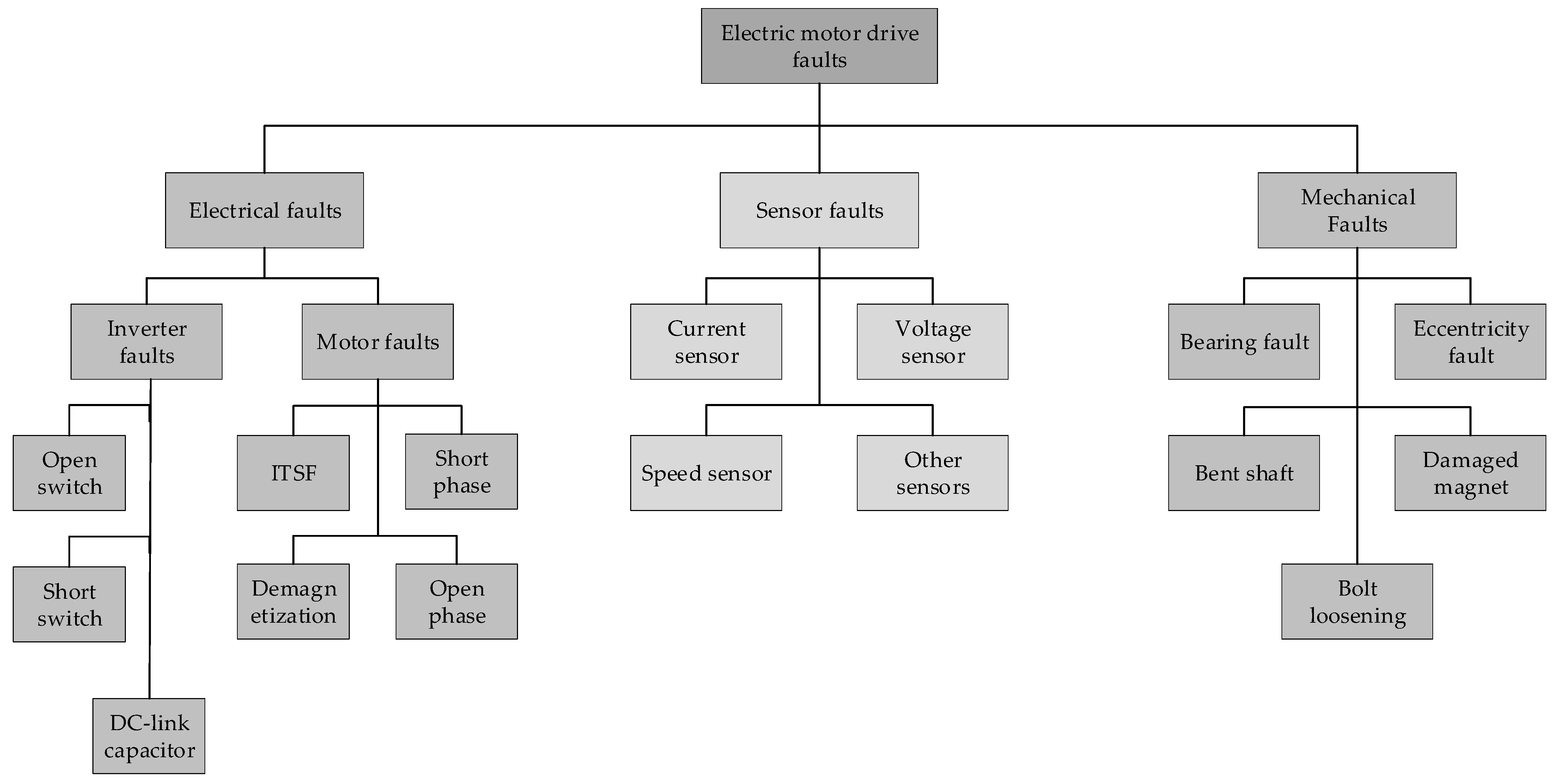
2.1. Electrical Faults

The main electrical faults, as noted above, are winding interturn short-circuit faults (ITSF) and open- or short-phase and demagnetization faults, which are related to the motor. Additionally, open circuits or short circuits in switches and DC-link capacitor failures are associated with the inverter.

2.1.1. Interturn Short-Circuit Fault

Breakdown and degradation in the stator turn-to-turn windings insulation of a PMSM are usually due to a power surge, moisture, or mechanical, electrical and thermal stresses, resulting in a short circuit in the windings [8]. This failure is known as the fault (ITSF) and has the highest failure rate among motor faults [9].
The shorted turns create an additional circuit loop connected to flux linkages created by other motor windings and the rotor magnet. A high-fault current is created in the ITSF windings because of the low impedance and high-coupled flux linkage voltage leading to stator overcurrent and overheating [10,11][10][11]. At the early stages of the ITSF, with failure in only a few percentages of turns, the motor can continue to operate with degraded performance. However, the heat produced by the overcurrent can damage the insulation of the nearby turns and expand to the whole phase at a high pace [12] and lead to a phase-to-phase or phase-to-ground short circuit and severe motor failure in a short time with high repair costs. Also, the rotor permanent magnet can potentially be permanently demagnetized by the high fault current in the extra current route [13,14][13][14]. Therefore, incipient fault detection becomes critical for ITSF. Usually, the ratio of the shorted turns to the number of turns in a coil is regarded as the severity of ITSF. As the severity increases, the induced back-EMF voltage of the shorted turns rises and subsequently, the short-circuit current rises rapidly, resulting in more system imbalance [15].

2.1.2. Demagnetization Fault

Physical damage, high-temperature operation, aging or an inverse magnetic field can all induce demagnetization, which reduces the strength of the permanent magnet (PM) inside the IPMSM. Also, an ITSF, if not detected and tolerated in time, can result in partial demagnetization due to the induced reverse magnetitic field [16]. Reversible and irreversible demagnetization are the two forms of demagnetization. The former is caused by a field weakening control, whereas the second suffers from permanent demagnetization. An inappropriate operating point of the IPMSM because of the combined influence of temperature and a shift in the permeance curve [17] is a key cause of irreversible demagnetization. If demagnetization happens, it lowers the torque of the PMSM due to the reduced PM flux linkage. Consequently, it negatively impacts the motor’s characteristics and efficiency [18]. The current in demagnetized PMSMs must increase to compensate for the effect of a weakened PM and produce the same torque as a healthy state [19]; nevertheless, this means increasing copper losses and temperature [20]. On the other hand, high temperatures can result in far more severe irreversible demagnetization [21]. Consequently, the reliability and safety of the system would be decreased. Utilizing fault detection and diagnosis technologies is vital to avoid such consequences. Demagnetization fault can result in additional frequency components in stator current and the vibration and result in pulsation in torque and speed. These signatures can be used for demagnetization fault detection [22,23][22][23].

2.1.3. Open or Short Switches in the Inverter

Inverters are used in electric motor drive systems as a core component. Due to the high-frequency operation, high power stresses, aging and other conditions, the switching devices are the components most expected to fail while in use (about 38% of faults in drivers [24]), which commonly appear as a short-circuit or open-circuit failure. Open-circuit faults usually occur because of a gate signal failure or disconnecting of the wire. Such a fault does not stop the drive system from operating [25]. As an open-circuit fault stops the defective phase winding stimulation in a switching device, the system operates in phase-locking mode. As a result, the drive system loses equilibrium, and the rotor is subjected to an imbalanced force, resulting in a considerable reduction in system performance [2] and noticeable vibrations and can end in secondary faults in the motor due to the lack of FDD. Short-circuit faults are usually the result of overvoltage, overheating, breakdown of the protection components or a wrong gate signal [25]. Furthermore, when a power switch is short-circuited, the defective phase winding is constantly stimulated, regardless of the rotor position, and causes instant overcurrent. Consequently, the faulty phase creates a significant, reversed braking torque during its demagnetization period, and the drive system’s stability is significantly damaged, resulting in a subsequent failure of the entire system [26]. In this case, the protective circuits come into effect as an overcurrent is produced immediately, making the inverter shut down; it needs to be repaired to operate again. Hence, identifying and isolating power transistor faults and their locations accurately and quickly is critical for the safe functioning of a PMSM drive.

2.2. Mechanical Faults

Mechanical faults are as important as electrical faults and need in-time detection. The main mechanical faults are bearing faults and air–gap eccentricity. Some other mechanical faults include a bent shaft, damaged magnet and bolt loosening [28][27].

2.2.1. Bearing Faults

A bearing fault is the most common fault among all possible motor faults, contributing about 40–50% [29][28]. Bearing faults can be in the inner raceway, outer raceway, cage or ball bearings. The main reasons behind the bearing fault are poor lubrication, mechanical vibrations, shaft misalignment, overload, corrosion and eventually fatigue, even under normal conditions. If the bearing defect is not detected and repaired in time, other forms of faults, such as air–gap eccentricity, ITSF and even complete motor failure, are expected [30][29]. Figure 1 in [31][30] illustrates the rolling bearing structure.

2.2.2. Air–Gap Eccentricity Faults

Some mechanical problems, such as unbalanced loads, shaft misalignments, rotor imbalance, missing bolt and bearing faults, result in a rotor eccentricity fault within the motor [28][27]. In fact, it is the uneven air gap between the stator and rotor and is categorized into three types: static eccentricity (SE), dynamic eccentricity (DE), and mixed eccentricity (ME). SE refers to the condition that the minimum air gap has a fixed value and hardly ever alters with time, mainly caused during the manufacturing stage. DE occurs where the minimum air gap location rotates along with the rotor and is brought on by rotor flaws, worn bearings, and bent shafts. The ME has both SE and DE defects simultaneously [32][31].

2.3. Sensor Faults

Different types of sensors, including current, voltage, speed, or position sensors, are needed to provide a motor drive control system with different feedback signals. A sensor fault refers to any defect or failure in such sensors which can happen due to vibration, temperature, moisture, etc. [33][32]. Sensor faults can be open circuits, gain deviation or high noise [34][33]. If a fault occurs in any of these sensors, incorrect information is fed to the motor’s monitoring and controller system, leading to degraded performance and even complete motor failure. Therefore, fault detection and diagnosis are essential to avoiding such failure and reduced reliability [35][34].

2.3.1. Current Sensor Faults

At least two current sensors are used to measure the phase currents of a three-phase PMSM. Current sensor faults can be found in three types, zero output, incorrect gain and dc offset, none of which need rapid detection and repair but can lead to reduced efficiency and overheating [2].

2.3.2. Voltage Sensor Faults

If the voltage sensor fault causes a rapid increase in the measured DC-link voltage, it can lead to system failure in a small period. In this situation, fast fault detection and repair are critical. Sometimes a fault can cause slight changes and deviations in the measured value, allowing the motor to operate for some time with reduced performance. Eventually, any fault in the voltage sensor must be detected and tolerated [2].

2.3.3. Speed or Position Sensor Faults

The rotor position and speed are measured by the position and speed sensors in the motor drive to feed the control system. Photoelectric incremental encoders are mostly used for this object. Any fault in this sensor can affect motor functionality. It can result in wrong-direction rotation, reducing the speed from the desired speed to zero, making the motor stop, or, most dangerously, increasing the speed more than desired to the maximum possible motor speed. The last situation results in persistent overload and even catastrophic accidents. As a result, FDD has a crucial role in preventing such conditions [2].

3. Battery System Faults

The potential faults of the battery pack can be classified into three main groups: battery abuse, connection faults, and sensor faults. The occurrence of each of these faults can result in heat generation and, if they are not detected or tolerated in time, can increase the aging speed and even result in thermal runaway and explosion [36][35]. Figure 2 shows a diagram of battery system faults. 


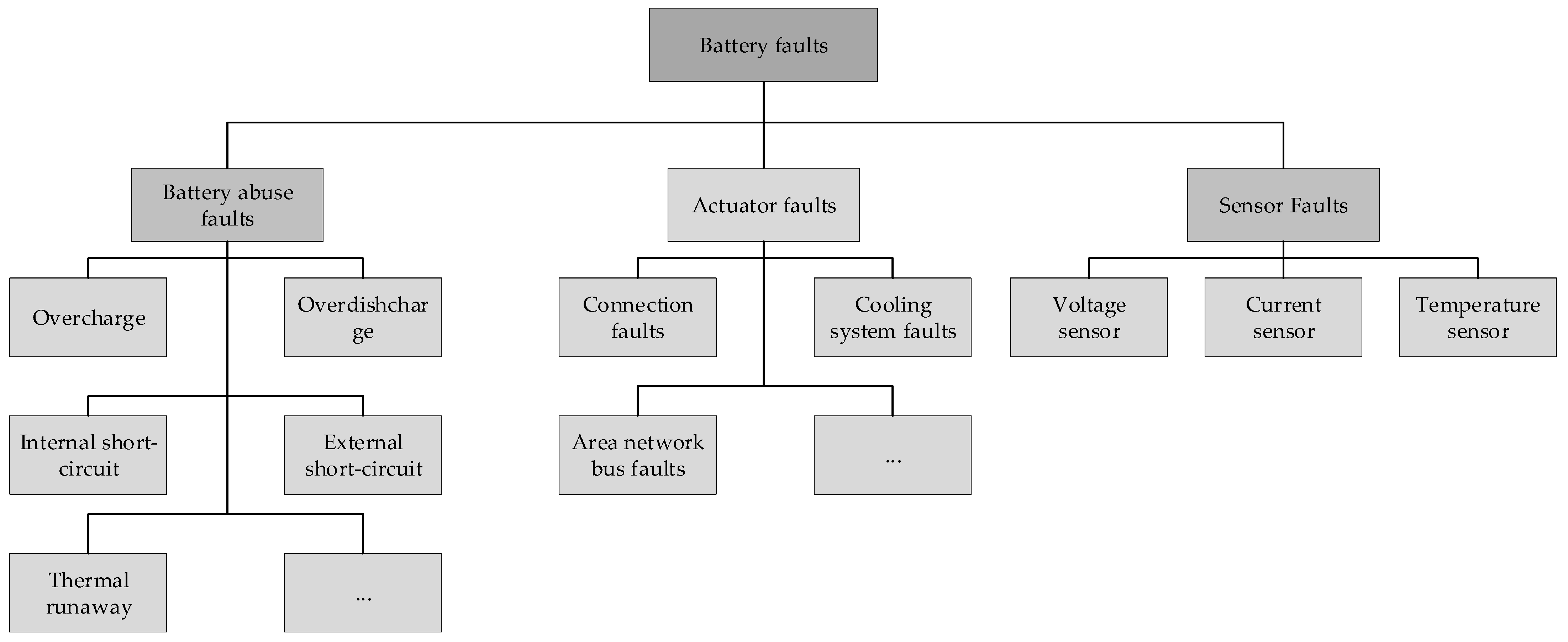
Figure 2. Various battery faults.

3.1. Battery abuse faults

This group of faults contains overcharge, over-discharge, internal short circuits, external short circuit, thermal runaway, etc. which can happen inside the battery. Errors in the battery management system and cell capacity degradation can result in overcharge and over-discharge faults. These faults can lead to chemical and physical damage to the battery, degrading the battery performance and safe operation [37][36]. The internal short circuit refers to the insulation failure between the layers inside the battery, while the external one notices the shorted positive and negative terminals [38][37]. An external short circuit is more dangerous and noticeable fault than an internal short circuit, which is negligible in the early stages. However, the internal short circuit can turn into an intense fault after a while [39][38]. Rapid voltage drop and thermal runaway are expected when a short circuit occurs.

3.2. Actuator Faults

Connection faults, cooling system faults, controller area network bus faults, etc. belong to this group of faults. Due to the need for a high level of energy in EV applications, the battery system usually consists of many battery cells connected in a parallel-series configuration. Due to the working environment of EV, temperature changes, vibration and aging, the connections can become defective. Loose connections can reduce the available power, resulting in potential accidents. Increasing the the resistance of the connection can cause heat production and affect the battery performance [40][39]. If the cooling system fails, the battery temperature may exceed the allowed temperature range and even lead to thermal runaway, so it is on of the considerable battery faults.

3.3. Sensor Faults

Battery management system (BMS) plays a crucial role in the safe, reliable and effective performance of EVs. This unit is responsible for several tasks, including estimating the state of charge (SOC) and state of health (SOH) of the battery, thermal management, cell balancing, etc., by monitoring the voltage, current and temperature of the cells [41][40]. In this regard, many current, voltage and temperature sensors are utilized in the battery system. Any defect and fault in these sensor can be reflected in the BMS performance and lead to further faults such as battery abuse faults and significant failures, all of which reduce the battery lifespan and safety.

References

  1. Popescu, M.; Goss, J.; Staton, D.A.; Hawkins, D.; Chong, Y.C.; Boglietti, A. Electrical Vehicles—Practical Solutions for Power Traction Motor Systems. IEEE Trans. Ind. Appl. 2018, 54, 2751–2762.
  2. Wang, X.; Wang, Z.; Xu, Z.; Cheng, M.; Wang, W.; Hu, Y. Comprehensive Diagnosis and Tolerance Strategies for Electrical Faults and Sensor Faults in Dual Three-Phase PMSM Drives. IEEE Trans. Power Electron. 2019, 34, 6669–6684.
  3. Zhang, L.; Zhu, C.; Yu, S.; Ge, D.; Zhou, H. Status and challenges facing representative anode materials for rechargeable lithium batteries. J. Energy Chem. 2022, 66, 260–294.
  4. Shete, S.; Jog, P.; Kamalakannan, R.; Raghesh, J.T.A.; Manikandan, S.; Kumawat, R.K. Fault Diagnosis of Electric Vehicle’s Battery by Deploying Neural Network. In Proceedings of the 6th International Conference on I-SMAC (IoT in Social, Mobile, Analytics and Cloud), I-SMAC, Dharan, Nepal, 10–12 November 2022; Institute of Electrical and Electronics Engineers Inc.: Piscataway, NJ, USA, 2022; pp. 346–351.
  5. Lang, W.; Hu, Y.; Gong, C.; Zhang, X.; Xu, H.; Deng, J. Artificial Intelligence-Based Technique for Fault Detection and Diagnosis of EV Motors: A Review. IEEE Trans. Transp. Electrif. 2022, 8, 384–406.
  6. Bhuiyan, E.A.; Akhand, M.A.; Das, S.K.; Ali, F.; Tasneem, Z.; Islam, R.; Saha, D.K.; Badal, F.R.; Ahamed, H.; Moyeen, S.I. A Survey on Fault Diagnosis and Fault Tolerant Methodologies for Permanent Magnet Synchronous Machines. Int. J. Autom. Comput. 2020, 17, 763–787.
  7. Niu, X.; Zhu, L.; Ding, H. New statistical moments for the detection of defects in rolling element bearings. Int. J. Adv. Manuf. Technol. 2005, 26, 1268–1274.
  8. Moosavi, S.; Djerdir, A.; Ait-Amirat, Y.; Khaburi, D. ANN based fault diagnosis of permanent magnet synchronous motor under stator winding shorted turn. Electr. Power Syst. Res. 2015, 125, 67–82.
  9. Nandi, S. Detection of stator faults in induction machines using residual saturation harmonics. IEEE Trans. Ind. Appl. 2006, 42, 1201–1208.
  10. Bonnett, A.; Soukup, G. Cause and analysis of stator and rotor failures in three-phase squirrel-cage induction motors. IEEE Trans. Ind. Appl. 1992, 28, 921–937.
  11. Urresty, J.-C.; Riba, J.-R.; Romeral, L. Diagnosis of interturn faults in pmsms operating under nonstationary conditions by applying order tracking filtering. IEEE Trans. Power Electron. 2013, 28, 507–515.
  12. Kim, K.-H.; Choi, D.-U.; Gu, B.-G.; Jung, I.-S. Fault model and performance evaluation of an inverter-fed permanent magnet synchronous motor under winding shorted turn and inverter switch open. IET Electr. Power Appl. 2010, 4, 214–225.
  13. Kim, K.-T.; Park, J.-K.; Kim, B.-W.; Hur, J. Comparison of the fault characteristics of IPM-type and SPM-type BLDC motors under Inter-Turn Faults conditions using Winding Function Theory. In Proceedings of the 2012 IEEE Energy Conversion Congress and Exposition, ECCE, Raleigh, NC, USA, 15–20 September 2012; pp. 1262–1269.
  14. Lee, Y.-S.; Kim, K.-T.; Hur, J. Finite-element analysis of the demagnetization of IPM-type BLDC motor with stator turn fault. IEEE Trans. Magn. 2014, 50, 889–892.
  15. Qi, Y.; Bostanci, E.; Gurusamy, V.; Akin, B. A Comprehensive Analysis of Short-Circuit Current Behavior in PMSM Interturn Short-Circuit Faults. IEEE Trans. Power Electron. 2018, 33, 10784–10793.
  16. Lee, H.; Jeong, H.; Kim, S.W. Detection of Interturn Short-Circuit Fault and Demagnetization Fault in IPMSM by 1-D Convolutional Neural Network. In Proceedings of the 2019 IEEE PES Asia-Pacific Power and Energy Engineering Conference (APPEEC), Macao, China, 1–4 December 2019.
  17. Hong, J.; Park, S.; Hyun, D.; Kang, T.-J.; Bin Lee, S.; Kral, C.; Haumer, A. Detection and Classification of Rotor Demagnetization and Eccentricity Faults for PM Synchronous Motors. IEEE Trans. Ind. Appl. 2012, 48, 923–932.
  18. Kim, K.-C.; Lim, S.-B.; Koo, D.-H.; Lee, J. The Shape Design of Permanent Magnet for Permanent Magnet Synchronous Motor Considering Partial Demagnetization. IEEE Trans. Magn. 2006, 42, 3485–3487.
  19. Ruoho, S.; Kolehmainen, J.; Ikaheimo, J.; Arkkio, A. Interdependence of demagnetization, loading, and temperature rise in a permanent-magnet synchronous motor. IEEE Trans. Magn. 2010, 46, 949–953.
  20. Espinosa, A.G.; Rosero, J.A.; Cusido, J.; Romeral, L.; Ortega, J.A. Fault detection by means of Hilbert-Huang transform of the stator current in a PMSM with demagnetization. IEEE Trans. Energy Convers. 2010, 25, 312–318.
  21. Joo, D.; Cho, J.-H.; Woo, K.; Kim, B.-T.; Kim, D.-K. Electromagnetic field and thermal linked analysis of interior permanent-magnet synchronous motor for agricultural electric vehicle. IEEE Trans. Magn. 2011, 47, 4242–4245.
  22. Faiz, J.; Nejadi-Koti, H. Demagnetization Fault Indexes in Permanent Magnet Synchronous Motors—An Overview. IEEE Trans. Magn. 2016, 52, 8201511.
  23. Yang, Z.; Shi, X.; Krishnamurthy, M. Vibration monitoring of PM synchronous machine with partial demagnetization and inter-turn short circuit faults. In Proceedings of the 2014 IEEE Transportation Electrification Conference and Expo: Components, Systems, and Power Electronics—From Technology to Business and Public Policy, ITEC, Beijing, China, 31 August–3 September 2014; Institute of Electrical and Electronics Engineers Inc.: Piscataway, NJ, USA, 2014.
  24. Zhang, Z.; Luo, G.; Zhang, Z.; Tao, X. A hybrid diagnosis method for inverter open-circuit faults in PMSM drives. CES Trans. Electr. Mach. Syst. 2020, 4, 180–189.
  25. Cai, B.; Zhao, Y.; Liu, H.; Xie, M. A Data-Driven Fault Diagnosis Methodology in Three-Phase Inverters for PMSM Drive Systems. IEEE Trans. Power Electron. 2017, 32, 5590–5600.
  26. Gan, C.; Chen, Y.; Qu, R.; Yu, Z.; Kong, W.; Hu, Y. An Overview of Fault-Diagnosis and Fault-Tolerance Techniques for Switched Reluctance Machine Systems. IEEE Access 2019, 7, 174822–174838.
  27. Siddiqui, K.M.; Bakhsh, F.I.; Ahmad, R.; Solanki, V. Advanced Signal Processing Based Condition Monitoring of PMSM for Stator-inter Turn Fault. In Proceedings of the 2021 IEEE 8th Uttar Pradesh Section International Conference on Electrical, Electronics and Computer Engineering, UPCON, Dehradun, India, 11–13 November 2021; Institute of Electrical and Electronics Engineers Inc.: Piscataway, NJ, USA, 2021.
  28. Nandi, S.; Toliyat, H.A.; Li, X. Condition monitoring and fault diagnosis of electrical motors—A review. IEEE Trans. Energy Convers. 2005, 20, 719–729.
  29. Ewert, P.; Orlowska-Kowalska, T.; Jankowska, K. Effectiveness analysis of pmsm motor rolling bearing fault detectors based on vibration analysis and shallow neural networks. Energies 2021, 14, 712.
  30. Guo, Z.; Yang, M.; Huang, X. Bearing fault diagnosis based on speed signal and CNN model. Energy Rep. 2022, 8, 904–913.
  31. Park, Y.; Fernandez, D.; Bin Lee, S.; Hyun, D.; Jeong, M.; Kommuri, S.K.; Cho, C.; Reigosa, D.D.; Briz, F. Online Detection of Rotor Eccentricity and Demagnetization Faults in PMSMs Based on Hall-Effect Field Sensor Measurements. IEEE Trans. Ind. Appl. 2019, 55, 2499–2509.
  32. Choi, K.; Kim, Y.; Kim, S.-K.; Kim, K.-S. Current and Position Sensor Fault Diagnosis Algorithm for PMSM Drives Based on Robust State Observer. IEEE Trans. Ind. Electron. 2021, 68, 5227–5236.
  33. Xia, J.; Guo, Y.; Dai, B.; Zhang, X. Sensor Fault Diagnosis and System Reconfiguration Approach for an Electric Traction PWM Rectifier Based on Sliding Mode Observer. IEEE Trans. Ind. Appl. 2017, 53, 4768–4778.
  34. El Khil, S.K.; Jlassi, I.; Estima, J.; Mrabet-Bellaaj, N.; Cardoso, A.M. Current sensor fault detection and isolation method for PMSM drives, using average normalised currents. Electron. Lett. 2016, 52, 1434–1436.
  35. Kang, Y.; Duan, B.; Zhou, Z.; Shang, Y.; Zhang, C. Online multi-fault detection and diagnosis for battery packs in electric vehicles. Appl. Energy 2020, 259, 114170.
  36. Lelie, M.; Braun, T.; Knips, M.; Nordmann, H.; Ringbeck, F.; Zappen, H.; Sauer, D.U. Battery management system hardware concepts: An overview. Appl. Sci. 2018, 8, 534.
  37. Rheinfeld, A.; Sturm, J.; Frank, A.; Kosch, S.; Erhard, S.V.; Jossen, A. Impact of Cell Size and Format on External Short Circuit Behavior of Lithium-Ion Cells at Varying Cooling Conditions: Modeling and Simulation. J. Electrochem. Soc. 2019, 167, 013511.
  38. Ouyang, M.; Zhang, M.; Feng, X.; Lu, L.; Li, J.; He, X.; Zheng, Y. Internal short circuit detection for battery pack using equivalent parameter and consistency method. J. Power Source 2015, 294, 272–283.
  39. Liu, G.; Ouyang, M.; Lu, L.; Li, J.; Han, X. Analysis of the heat generation of lithium-ion battery during charging and discharging considering different influencing factors. J. Therm. Anal. Calorim. 2014, 116, 1001–1010.
  40. Samanta, A.; Chowdhuri, S.; Williamson, S.S. Machine Learning-Based Data-Driven Fault Detection/Diagnosis of Lithium-Ion Battery: A Critical Review. Electronics 2021, 10, 1309.
  41. Samanta, A.; Chowdhuri, S.; Williamson, S.S. Machine Learning-Based Data-Driven Fault Detection/Diagnosis of Lithium-Ion Battery: A Critical Review. Electronics 2021, 10, 1309.
More
Video Production Service