Your browser does not fully support modern features. Please upgrade for a smoother experience.
Please note this is a comparison between Version 1 by Cyrille Dongmo and Version 2 by Jessie Wu.
Semi-formal software techniques have been very successful in industry, government institutions and other areas such as academia. Arguably, they owe a large part of their success to their graphical notation, which is more human-oriented than their counterpart text-based and formal notation techniques. However, ensuring the consistency between two or more models is one of the known challenges of these techniques.
- URN process
- models consistency
- GRL process
- UCM process
- jUCMNav
1. Introduction
Mainly due to their graphical modeling approach, which makes them flexible and more human-oriented than, for example, text-based or mathematical-based notation techniques, semi-formal (visual) methods have been very popular [1][2][3]. Most of them allow for the modeling of various system view points at different abstraction levels including, for instance, models specifying user requirements, system and architectural design. With tools providing graphical objects to aid the specification and design of systems, the production of graphical models for the system under development is made relatively easy. However, some of the known challenges are in ensuring the consistency between different models describing the same system and in proposing a bridging mechanism to facilitate the transformation from one model to another. This problem is better understood when taken from the perspective of the model-driven engineering (MDE) approach, where conceptual models are continuously and progressively refined into more detailed ones until the text or code implementing the last model is obtained. Thus, one of the main difficulties being to develop a reusable and traceable transformation process to automatically generate a lower-level model from the more abstract one. In the case of URN, such issue evidently calls for the improvement of the existing (construction) methods. In this regard, this rpapesearchr aims to address the problem in URN with the purpose of improving its construction process.
URN provides link elements to ensure consistency between Goal-Oriented Requirement Language (GRL) L and UCM models, and in so doing, the correctness of URN models. To date, and to the best of our knowledge, not much has already been done to reinforce such links at a practical level.
The User Requirements Notation (URN) is a standardized semi-formal, visual, requirements notation that enables the elicitation, modeling and specification, as well as the analysis and validation of user requirements including stakeholder goals [4][5][6]. It comprises two complementary languages: the Goal-Oriented Requirement Language (GRL) and the Use Case Maps (UCMs) [7].
2. Related Works
A similar work by Akhigbe et al. [8] suggests the use of mapping rules to statically link GRL elements to those of UCM. The rules were formalized with OCL and integrated, by means of meta-data, into the main URN tool which is jUCMNav. It is ouresearchers' observation that the main weakness of the mapping rules is the limited flexibility and the broad nature of the proposed rules that map not GRL elements to UCM elements but rather a group of elements (GRL Intentional elements) to another group of UCM sub-maps. At an early phase of software development, the flexibility of the requirements analysis and specification methods or techniques is valuable in the sense that, at such stage, alternative solutions need to be elaborated and evaluated to facilitate decision making.
Sebastián, Gallud and Tesoriero [9] found in their systematic mapping of studies on code generation with the model-driven architecture (MDA) technique that there are few publications regarding the computation independent model (CIM) layer of the MDA showing a research line that may be worth of exploration. In the same vein, this could be an indicator of the challenges faced by software practitioners to develop abstract models to accurately and consistently represent business requirements for the software system. In a survey aiming to understand practitioners’ challenges on Software Modeling, Ozkaya and Erata [10] found that models’ analysis and management are among the primary modeling challenges for software practitioners.
3. The URN Meta-Model
The URN basic structural features in Figure 1 describes containers for URN, GRL and UCM specifications [4].
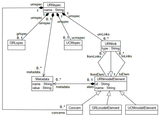
Figure 1. URN conceptual model [4].
The URN meta-model, namely, URNspec is the root element of the URN specification comprising a GRL specification (GRLspec), UCM specification (UCMspec), URN link elements (URNlink) and meta-data. GRLspec specifies the meta-model for GRL specifications which building blocks are GRL model elements (GRLmodelElement). On the other side, UCMspec specifies the meta-model for UCM specifications. Similarly to GRL specifications, the building blocks for a UCM specification are instances of the UCM model elements (UCMmodelElement). Finally, URNlink is a container for all relationships between URN model elements, especially GRL and UCM model elements. Instances of URN link elements are links connecting URN model elements from one to another.
4. The Goal-Oriented Requirement Language (GRL)
The Goal-Oriented Requirement Language, denoted GRL, is a visual modeling notation that aims to address the “Why” of a system at the requirements level, using concepts such as actor, goal, softgoal, task, belief and resource to conceptualize requirements artifacts and the link to establish relationships between those artifacts [4][11][12]. The GRL meta-model from which GRL specifications are constructed (GRLspec) is described in detail in the URN standard document [4]. The GRL model elements are partitioned into two groups: The first includes objects of the class known as GRLLinkableElement, comprising actors’ definitions and intentional elements that are used to model requirements artifacts. An actor specifies an entity that has intentions and may develop strategies to perform their intentions. They are therefore the containers of intentional elements. The second group is formed by objects of the class named ElementLink. They are used to create dependencies between actors, to model the decomposition of intentional elements and to specify the contribution of some intentional elements to satisfy or satisfice other intentional elements. Link elements are important concepts that serve to specify the decomposition, refinement and operationalization of intentional elements.
5. The Use Case Maps (UCMs)
The Use Case Map (UCM) is a standardized scenario-based requirements notation technique whose original purpose is to bridge the gap between requirements and design [7][13]. The notation has been very successful due to the use of simple graphical elements to describe, in a map-like diagram, service functionalities superimposed on the organizational structure of complex and distributed systems [14]. A UCM specification is constructed from various model elements, abstracted by the meta-class named UCMmodelElement [4]. The UCMmodelElement constitutes the blueprint for UCMs’ building blocks that include variables, scenarios, resources, components, responsibilities and UCMmap (see Figure 58, URN [4]). The UCMmap meta-model in (Figure 60, URN [4]), is one of the most important building block that combines, by means of node connectors (NodeConnection), most of the UCM elements known as path elements to construct individual UCM maps.
The basic function of a UCM specification is to model and reason about systems functionalities. An important characteristic of UCM is that UCM model elements can be combined in different ways to construct mechanisms that specify different aspects of a system. For example, the And-fork and And-join connectors associated with variables can be used to specify concurrency or parallelism in a system.
6. The User Requirements Notation Construction Tool: jUCMNav
6. The URN Construction Tool: jUCMNav
jUCMNav is an integrated environment for UCMs and GRL model construction [12][15]. It is a user-friendly graphical editor under the Java-based open-source Eclipse platform. jUCMNav provides, among other functionalities, the support for exporting URN models to external tools and those for importing from external sources. Such facilities allow jUCMNav to communicate with other systems via different types of file formats including XML, MSC (Message Sequence Charts) files and CSM (Core Scenario Model) files. The tool provides for visual link between the two URN models and implements strategies for evaluating GRL models. It equally provides the mechanisms for UCM path traversal (see [16][17]).
References
- Cervantes-Ojeda, J.; Gómez-Fuentes, M.; Chacón-Acosta, G. Can non-developers learn a simplified modeling notation quickly? J. Softw. Evol. Process. 2022, 34, e2481.
- Grobelna, I. Scratch-Based User-Friendly Requirements Definition for Formal Verification of Control Systems. Inform. Educ. 2020, 19, 223–238.
- Canché, M.; Ochoa, S.F.; Perovich, D.; Gutierrez, F.J. Analysis of notations for modeling user interaction scenarios in ubiquitous collaborative systems. J. Ambient. Intell. Humaniz. Comput. 2022, 13, 5321–5333.
- ITU-T, Recommendation Z.151 (10/12), User Requirements Notation (URN)—Language Definition, Geneva, Switzerland. 2012. Available online: https://www.itu.int/rec/T-REC-Z.151/en (accessed on 6 June 2023).
- Amyot, D.; Mussbacher, G. URN: Toward a New Standard for the Visual Description of Requirements. In Telecommunications and Beyond: The BroaderApplicability of SDL and MSC; Sherratt, E., Ed.; Springer: Berlin/Heidelberg, Germany, 2003; pp. 21–37.
- Amyot, D.; Mussbacher, G. User Requirements Notation: The First Ten Years, The Next Ten Years (Invited Paper). J. Softw. 2011, 6, 747–768.
- Buhr, R.J.A.; Casselman, R.S. Use Case Maps for Object-Oriented Systems; Prentice Hall: Hoboken, NJ, USA, 1999.
- Akhigbe, O.; Amyot, D.; Anda, A.A.; Lessard, L.; Xiao, D. Consistency Analysis for User Requirements Notation Models. In Proceedings of the iStar, Beijing, China, 12–13 September 2016; pp. 43–48.
- Sebastián, G.; Gallud, J.A.; Tesoriero, R. Code generation using model driven architecture: A systematic mapping study. J. Comput. Lang. 2020, 56, 100935.
- Ozkaya, M.; Erata, F. Understanding Practitioners’ Challenges on Software Modeling: A Survey. J. Comput. Lang. 2020, 58, 100963.
- Liu, L.; Yu, E. From Requirements to Architectural Design—Using Goals and Scenarios. In Proceedings of the ICSE 2001, Toronto, ON, Canada, 12–19 May 2001.
- Roy, J.F.; Kealey, J.; Amyot, D. Towards Integrated Tool Support for the User Requirements Notation. In System Analysis and Modeling: Language Profiles; Gotzhein, R., Reed, R., Eds.; Lecture Notes in Computer Science; Springer: Berlin/Heidelberg, Germany, 2006; Volume 4320, pp. 198–215.
- Buhr, R.J.A. Use Case Maps: A New Model to Bridge the Gap Between Requirements and Design. In Proceedings of the SCE 95—Conttribution to the OOPSLA 95 Use Case Map Workshop, Austin, TX, USA, 15 October 1995; pp. 1–4.
- Amyot, D.; Buhr, R.J.A.; Gray, T.; Logrippo, L. Use Case Maps for the Capture and validation of Distributed Systems Requirements. In Proceedings of the ISRE’99, Fourth International Symposium on Requirements Engineering, Limerick, Ireland, 7–11 June 1999.
- Mussbacher, G.; Amyot, D. Goal and Scenario Modeling, Analysis, and Transformation with jUCMNav. In Proceedings of the ICSE Companion, Washington, DC, USA, 16–24 May 2009; pp. 431–432.
- Mussbacher, G.; Ghanavati, S.; Amyot, D. Modeling and Analysis of URN Goals and Scenarios with jUCMNav. In Proceedings of the 2009 17th IEEE International Requirements Engineering Conference, Washington, DC, USA, 31 August–4 September 2009; pp. 383–384.
- Amyot, D.; Rashidi-Tabrizi, R.; Mussbacher, G.; Kealey, J.; Tremblay, E.; Horkoff, J. Improved GRL Modeling and Analysis with jUCMNav 5. In Proceedings of the iStar, Valencia, Spain, 17–18 June 2013; pp. 137–139.
More