1. Introduction
Additive manufacturing (AM), commonly known as 3D printing
[1], is the technology used to manufacture parts and objects through layer-by-layer deposition of materials. AM is considered one of the most innovative manufacturing technologies of the 21st century. It integrates the leading world technologies, e.g., digital modeling, machining, material processing, and metallurgical engineering. According to ISO/ASTM 529000:2021, AM processes can be divided into the following categories, as shown in
Figure 1.
AM offers significant benefits in reducing cycle time and saving raw materials by depositing material layer-by-layer under computer control. Especially, it can generate complicated geometrical features in the parts with high precision and lower dependency on cutting tools, dies, fixtures, and other complex machining processes
[2][3][2,3].
Powder bed fusion (PBF) and directed energy deposition (DED) have recently attracted more attention among all available AM technologies. Although PBF can produce parts with complex geometries and high accuracy, it also has some drawbacks, including high costs (operational cost, equipment cost, material cost) and the use of metal powder, which can be very unhealthy for humans. Furthermore, a controlled environment is needed where the PBF process takes place to prevent people from inhaling the toxic powder. DED is a promising method for AM of metals to overcome the aforementioned issues. DED is an AM methodology in which focused thermal energy is utilized to melt the material as it is deposited. In DED, the wire or powder material is used as feedstock and a heat source (plasma, electric arc, laser, or electron beam) for material deposition on a substrate surface. Although there is a lower resolution in DED compared to PBF, the material deposition rate is much higher in DED. However, some studies of AM technologies also reported a few drawbacks to DED-based AM methods. These drawbacks include the utilization of large volumes of inert gases in laser-based DED, the high vacuum required in electron-based DED, etc. Furthermore, powder-based DED has lower material deposition efficiency than wire-based DED, as a minor portion of the total powder will not be melted. That is why if the wire is used as a feedstock in DED instead of metal powder, it omits the need for recycling and powder protection systems, and the cost of raw materials is reduced significantly. A comparison of different AM processes is presented below in Table 1.
Table 1. Comparison of AM processes [4][5][6][7][8]. Comparison of AM processes [4,5,6,7,8].
2. WAAM Process
2.1. Introduction to WAAM
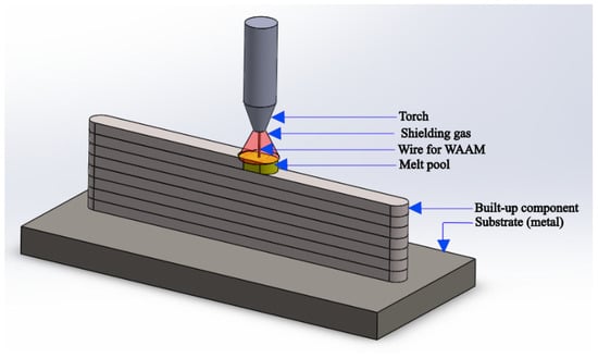
The wire arc additive manufacturing (WAAM) process has become a renowned AM process in the recent decade, and it is one of the DED technologies. WAAM has been derived from classical arc welding technology
[9][10][11][9,10,11]. In WAAM process, the wire is melted through heating by using an electric arc and then transferred to the molten metal pool. Later, it solidifies at the melt pool boundary and produces the part layer-by-layer
[12]. A typical WAAM process is shown in
Figure 2 below.
WAAM process has the potential to develop structures that can be extended to tens of meters and can fabricate fully dense parts with large dimensions, along with higher manufacturing efficiency and low production costs. It is also suitable for repairing and maintaining damaged parts and components. Generally, the direct cost of metal wire used in WAAM process is roughly 10% of the metal powder having the same weight
[12]. A comparison of the material deposition rate in WAAM process with other AM processes is presented below in
Table 2.
Table 2. Comparison of material deposition rates of major AM processes for steels [13][14]. Comparison of material deposition rates of major AM processes for steels [13,14].
WAAM process can be divided into three major categories depending on the type of arc-based welding technology used to melt the feed wire and generate a 3D object/structure layer by layer
[15][16][17][18][15,16,17,18]. These three different types include gas tungsten arc welding (GTAW), plasma arc welding (PAW), and gas metal arc welding (GMAW), as shown in
Figure 3.
Figure 3.
Types of WAAM process.
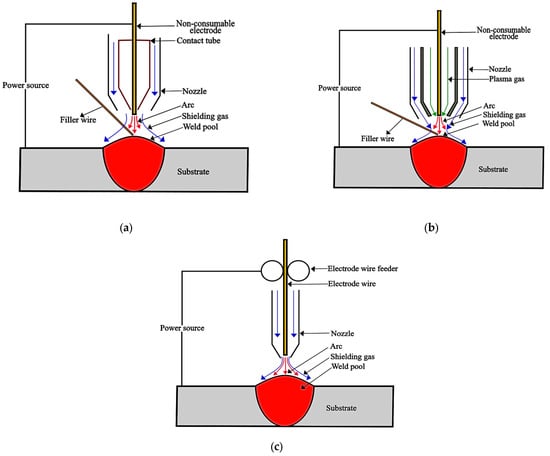
In GTAW-based WAAM, an electric arc is generated between a non-consumable tungsten electrode and the substrate material for heat generation, as shown in Figure 4a below. A filler wire is fed from the side, which melts due to the arc’s heat and deposits on the substrate’s surface to get the desired geometry (width, height, cross-section, etc.) and mechanical properties. The PAW process is similar to GTAW in that a non-consumable electrode is used in both methods. However, PAW differs from GTAW in welding torch construction and is more efficient than GTAW because the plasma arc is constricted in a nozzle. In PAW, an arc is generated between the tungsten electrode and the water-cooled nozzle, as shown below in Figure 4b. The inert gas flowing through the arcing zone of the torch gets ionized, i.e., the gas turns into a plasma state. This plasma jet is then transferred through a small orifice to the substrate. This plasma jet turns the filler wire into molten form due to the high heat. In addition, shielding gas is used to protect the molten pool from contamination. But the initial cost of PAW is very high compared to GMAW and GTAW. GMAW is widely used for WAAM process nowadays compared to other WAAM processes due to its higher material deposition rate, high material utilization, and shorter lead time. In GMAW, the wire works as a consumable electrode, as shown in Figure 4c below. The arc generated between the wire and the workpiece melts the wire material and deposits the molten material on the substrate’s surface.
Figure 4.
Types of WAAM processes. (
a
) GTAW; (
b
) PAW; (
c
) GMAW.
GMAW consists of metal inert gas (MIG) and metal active gas (MAG). In MIG, a non-reactive (inert) gas, i.e., helium or argon, is used. MIG is mainly used for non-ferrous metals. MAG uses carbon dioxide or a mixture of inert gases, i.e., a trimix of Ar + CO2 + O2, for shielding purposes. MAG is primarily used for ferrous metals. The material deposition rate of the GMAW process is higher as compared to other WAAM processes, and this comparison is presented below in Table 3.
Table 3. Comparison of the material deposition rates of different WAAM processes [3][19][20]. Comparison of the material deposition rates of different WAAM processes [3,19,20].
GMAW has four metal transfer modes: short-circuiting, globular, spray, and pulsed spray. Each metal transfer method has distinctive characteristics related to the welding current, equipment, and electrode type
[21]. In the conventional GMAW welding process, during standard short-circuiting transfer (dip transfer) mode, when the welding electrode comes in contact with molten pool and immerses in it, short-circuiting occurs, and an enormous current flows through it. Thus, it results in the abrupt melting of the electrode wire, so droplet transfer happens via the surface tension of the molten metal pool. The arc re-ignites, and the hot process after the completion of the metal transfer process continues. A significant improvement in WAAM was achieved when the CMT (cold metal transfer) welding process was introduced. CMT is an improved version of GMAW and is based on the short-circuit transfer mode. The Austrian company “Fronius” developed the CMT method, a renowned method for generating meager heat input and high arc stability using an innovative wire feeding setup with a digital control system
[22]. When the wire electrode tip comes in contact with the molten metal pool, the “robacter drive” servomotor reverses the filler wire via digital process control. Hence, it results in causing the wire to withdraw, producing droplet cutting, while the welding current quickly decreases to a near-zero value
[23]. Thus, it causes lower heat input and less spatter during the material deposition. CMT can be divided into four types, i.e., CMT-conventional, CMT-advanced, CMT-pulse, and CMT-advanced pulse. Each mode has its unique features and characteristics.
2.2. General Steps Involved in WAAM Process
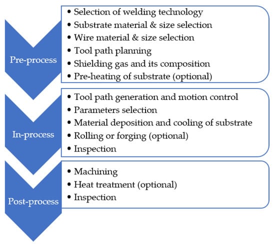
The main steps involved in WAAM process, as reported by literature
[2][24][2,24], are presented below in
Figure 5.
Figure 5.
Steps involved in WAAM process.
2.3. Process Parameters Used in WAAM Process
2.3.1. Introduction to Different WAAM Process Parameters
The process parameters used in WAAM process vary according to the type of WAAM process and the wire material. In WAAM process, material deposition is based on melting a wire using an arc as a heat source for fabricating or repairing a component. During material deposition, the inter-pass temperature between layers increases due to the heat accumulation as further layers are added. The process parameters are crucial for producing a good-quality part, i.e., a defect-free structure with excellent mechanical properties. These process parameters include welding current, voltage, torch travel speed, wire feed speed, interlayer temperature, interlayer dwell time, shielding gas composition and flow rate, torch and substrate angle, electrode diameter, heat input, and contact tip-to-work distance (CTWD). These parameters affect the properties of WAAM product differently, and a suitable combination of these parameters is needed for specific objectives, i.e., high mechanical strength, lower surface roughness, etc.
Wire Feed Speed
Yildiz et al.
[25] studied the effect of the WFS (wire feed speed) to TS (torch speed) ratio on the weld bead geometry and mechanical properties. This study showed that the WFS/TS ratio is the most crucial parameter in WAAM process for controlling heat input. Heat input is linearly correlated with the characteristic weld bead geometry, including the weld bead height, width, penetration, penetration area, and reinforcement area, for the analyzed parameter range. An inverse relationship was observed between heat input and hardness in single weld beads. Wang et al.
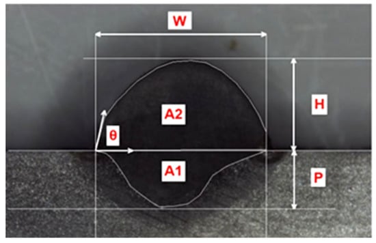
[26] studied the effect of wire feed speed and other parameters on the weld bead geometry. This study showed that as the wire feed speed increases in GTAW-based WAAM of 4043 Al-alloy, the weld bead height increases while its width decreases. It was also reported that the arc energy required to melt the wire increases as the wire feed speed increases. Thus, it may lead to a lack of fusion and a decrease in the width of the bead. Different features of a typical weld bead are presented below in
Figure 6.
Figure 6. Schematic diagram of different weld bead features (material: ER120S-G), copyright Springer Nature, reproduced with permission
[25]. where: W = Width; P = Penetration; H = Height; A1 = Penetration area; A2 = Reinforcement area; Θ = Angle of contact.
Torch Travel Speed
Dinovitzer et al.
[27] examined the effect of torch travel speed and other parameters on microstructure and bead geometry in WAAM of Hastelloy X alloy. In this study, statistical tools, i.e., Taguchi and ANOVA (analysis of variance), were used to determine the effect of process parameters (wire feed, travel speed, current, and argon flow rate) on the bead’s microstructure and geometry (bead shape and size, roughness, melt through depth, and oxidation level). This research revealed that current and travel speed significantly affect the weld bead’s microstructure and geometry. It was revealed that torch travel speed is inversely related to the heat input in WAAM process. In WAAM process, WAAM component’s microstructure depends on the heat input; hence, the part’s microstructure also relies on the torch’s travel speed. Furthermore, the effect of torch travel speed on the width of the weld bead was significant compared to its impact on the bead height because the travel speed affects the angle of contact (wetting angle).
Heat Input
Heat input is very critical in WAAM process. Multiple fusion and solidification cycles produce irregular heat propagation in the as-manufactured part. This non-uniform heat input accumulation and distribution defines the part’s formation (shape and volume of the bead), mechanical properties, and microstructure obtained via WAAM process
[28][29][28,29]. Heat input in WAAM process affects internal defect formation, phase transformation, residual stresses, and distortion
[30].
Heat input control is vital for alloys subjected to liquation cracking. As with increasing heat input, the quantity of liquated material increases, hence the chances of cracking. As WAAM process involves partial melting of the previous layer/bead, improper control of heat input will assist in partial liquation at the fusion zone
[31][32].
Moreover, an increase in heat input will affect the cooling rates of WAAM components and, hence, the part’s microstructure. As microstructure affects the part’s mechanical properties, heat input indirectly affects the mechanical properties of WAAM component. Sometimes, residual stresses also arise in the part produced through WAAM process due to high heat input; in fact, that part experiences thermal stress with the deposition of each weld bead. Thus, appropriate welding technology, interlayer dwell time, and path strategy are needed to mitigate this effect.
Substrate Temperature
The substrate’s pre-heat temperature defines the shape of the deposited material. As the pre-heat temperature increases, the deposited bead’s width increases, whereas its height decreases
[31][32][32,33]. Thus, pre-heating the substrate leads to smooth material deposition and, in return, also improves the surface deformation of the metal deposited.
Interlayer Temperature
The inter-layer temperature is crucial for obtaining the desired shape of the end product in the multi-layer WAAM process. Proper inter-layer temperature is essential for obtaining a smooth and stable surface while depositing material. Hence, properly controlling the workpiece temperature will improve its surface finish, reduce residual stress, and improve its mechanical properties
[33][34][34,35]. Therefore, adequate interlayer cooling time (dwell time) is needed to get the desired interlayer temperature. This time should be chosen based on the trade-off between desired product features and production time. The idle waiting time will increase for lower inter-layer temperatures, resulting in a loss of useful production time
[35][36].
Electrode Extension or Electrode Stick-Out
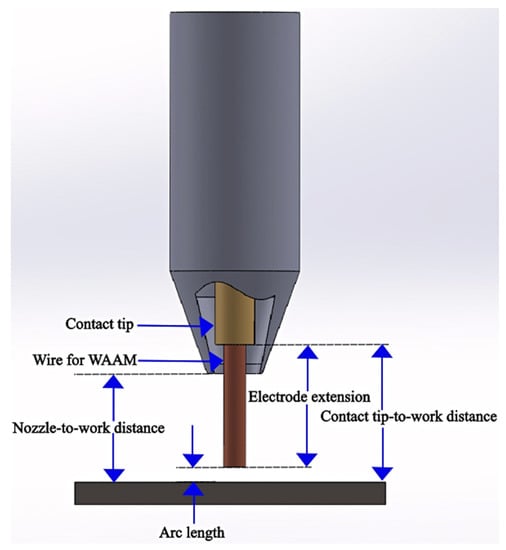
Electrode extension, or electrode stick-out, is the distance between the end part of the contact tip and the wire end, as shown in Figure 7 below. Electrical resistance increases with an increase in electrode extension. Thus, it influences the melting of the wire, and in return, it affects the weld bead geometry.
Figure 7.
Electrode to work distance, arc length, and other features in MIG.
Extended electrode extension causes the pre-heating of the electrode wire. If the electrode extension is insufficient, the electrode will not get sufficiently pre-heated. Increasing the electrode extension while keeping the arc length constant enlarges the electrical resistance. More material has to be deposited due to an increment in the electrode extension but with low heat energy provided by the arc produced due to a rise in electrical resistance. In return, it will result in slight penetration and steep-crowned weld bead geometry.
Arc Length
The arc length is the distance between the welding wire tip and the substrate, as shown in
Figure 7 above. The roughness of the deposited layer can be reduced by efficient control of the arc length
[32][33].

