Your browser does not fully support modern features. Please upgrade for a smoother experience.
Please note this is a comparison between Version 1 by Prashanth Konda Gokuldoss and Version 2 by Rita Xu.
Metallic additive manufacturing is expeditiously gaining attention in advanced industries for manufacturing intricate structures for customized applications.
- additive manufacturing
- coatings
- metallic coating
1. Introduction
The advent of technology has led to an upsurge in the demand for more personalized products according to customer needs. In the age of the industrial revolution, there is a need for economically viable components without compromising the quality of several applications. The size and distribution of manufactured goods have challenged industries. Additive manufacturing (AM) is an emerging technology that provides flexibility in producing intricate parts at nominal costs, unlike conventional methods [1]. The technology has been filling the gap between conventional manufacturing methods and subtractive technologies for a decade. To explore the possible applications of AM processes, hybridization with conventional methods offers merged advantages. The higher material efficacy offered by AM technologies over the subtractive processes suppresses the expensive equipment costs [2]. Several attempts have been made by the research community to delve into different prospects of AM for metallic materials.
The idea of manufacturing parts through AM has been prevalent for a decade, and the applications include rapid prototyping, the generation of models for large-scale production, conducting different tests, and the validation of such models [3]. With the inception of the fourth industrial revolution, the direct manufacturing of products through AM emerged, including in the automotive, electronics, nuclear, aerospace, and bio-medical sectors. Unlike the available strategies such as servitization [4], presumption [5], and personalization [6], AM technology stands out as an effective manufacturing method among the leading industries. The AM process has gained popularity among researchers for the direct printing of parts, microstructure–property correlation, materials design, product design, and end utilization of the product [7][8][9][7,8,9]. Lately, AM has been used in conjunction with conventional manufacturing methods. Subtractive manufacturing accounts for controlled material removal from the substrate to obtain the final product, whereas in AM, layer-by-layer deposition takes place on the end surface [10]. As compared to traditional manufacturing methods, AM is intrinsically less harmful to the environment and leads to zero waste in terms of socio-economical value addition.
According to the American Society for Testing and Materials (ASTM International) standards, AM is classified based on the material used as feedstock, the state of fusion, the distribution of material, and the type of process [11]. As per ASTM standards, metal additive manufacturing (MAM) methods are broadly classified into direct energy deposition (DED)/powder-fed fusion (PFF) and powder bed fusion (PBF) processes. Apart from these, sheet lamination and binder jetting are also counted by ASTM as alternative MAM methods [12][13][12,13]. Some of the other potential methods include friction stir additive manufacturing [6][7][6,7], cold spraying [8][9][8,9], direct metal writing [10][11][10,11], and diode-based processes [14]. However, these techniques are still under consideration by ASTM to be included in the AM classification list. A generalized classification of the AM techniques is presented in Figure 1.
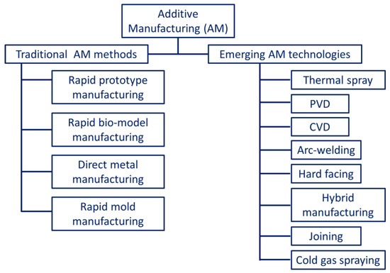
Figure 1. Generalized classification of the different additive manufacturing technologies.
The metallic parts manufactured through AM processes often have irregular surface morphology when compared to those produced by conventional methods. The irregularities are the result of layer-by-layer deposition and fusion occurring on the material surfaces [15]. These drive the motivation to develop different alloy-rich layers or coatings on irregularly finished surfaces. The performance limitations of engineering materials for different applications have encouraged researchers to process them through AM coatings. In this regard, different AM methods are used in conjunction with the available conventional methods. Figure 2 indicates a broad outline of coatings on engineering materials through additive manufacturing technologies [16].
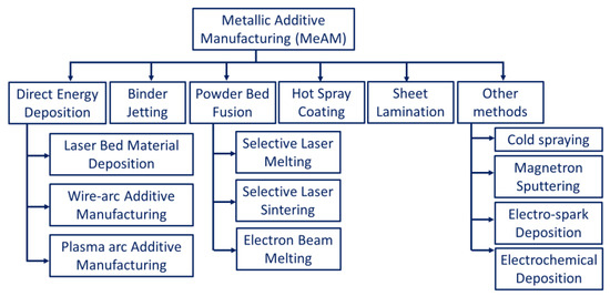
Figure 2. Broad classification of metallic additive manufacturing processes.
The factors that affect the irregularity of the surfaces include the staircase effect, the agglomeration of partially fused material, spattering, splashed particles (evaporation and balling effect), the instability of molten pool (wetting effect), etc. [17][18][19][17,18,19]. For instance, the addition of zinc in powder bed fusion processes enhances the wetting properties, whereas the uncontrollability in the movement of the molten pool at the boundaries is quite challenging [20][21][20,21]. Studies indicate the presence of irregularity in surface roughness on intricate geometries with inclined surfaces [22][23][22,23]. A change in inclination angle affects the surface roughness. The supporting structures when removed from the part geometry also alter the surface quality. The features formed on the surfaces become stress concentration sites for crack formation. In addition to this, the size of feedstock, deposition parameters, and surface morphology affect the surface morphology of the AM components [24][25][26][24,25,26]. For example, in the direct energy deposition (DED) process, the surface waviness is a result of the weld beads generated due to a large molten metal pool that is difficult to control [25]. Owing to the issues in the conventional AM processes, the interest among the research community in providing innovative solutions has accelerated. To minimize the manufacturing costs as well as to address the issues, AM methods were developed for coatings or surface modification. The urge to obtain diverse surface properties on a single component drove researchers to adapt additive manufacturing as a tool for coatings and surface modification. Different engineering materials are subjected to AM methods to modulate their surface morphologies and incorporate multiple properties in a single component.
2. Need of Metallic Coatings
Thin film coatings usually possess a thickness of less than 0.1 μm, whereas thick film coatings have a thickness of more than 0.1 mm. As discussed earlier, coatings are made through AM to obtain enhanced properties on different components. Some of the significant advantages of coatings are as follows [27]:-
Ease of controlling the surface chemistry.
-
Improving mechanical properties such as hardness, toughness, adhesion strength, etc.
3. Applications of Metallic Coatings
Some of the major functionalized applications of the AM metallic coatings are as follows:-
Aerospace, automotive, and missiles: parts to prevent loss in wear and corrosion.
-
Automotive: brakes, bolted joints, etc.
- Inducing hydrophobicity or hydrophilicity to the surfaces.
-
Electronics: fuel cells, sensors, MEMS/NEMS, field effect devices.Enhancing anti-corrosive properties.
-
Bio-medical: sterilization, cell adhesion, bio-implants such as pacemakers, and stents for dental application.Increasing bioactivities and improve biocompatibility.
-
Textile: self-cleaning fabrics, biofilms, anti-microbial surfaces, UV-protective materials (roofs, curtains, awnings, tents).Improving tribological performance in terms of wear and friction.
-
Machine tools: cutting tools, electrodes, AFM tip, die, and molds.
-
Power sector: turbine blades, heat exchangers, valves, and boiler parts.
4. Different Metallic Coatings through Additive Manufacturing
4.1. Powder Bed Fusion
Powder bed fusion (PBF) includes the fusion of powders on the bed due to the introduction of a high amount of thermal energy. The high-dimensional stability obtained through this method whilst producing intricate and complex shapes makes it the most popular method in the metallic coating AM technologies. A wide range of printable powders (materials composition including Al-based [28][29][30][31][32][33][34][35][36][37][38][39][40][41][28,29,30,31,32,33,34,35,36,37,38,39,40,41], Fe-based [42][43][44][45][46][47][48][49][50][51][42,43,44,45,46,47,48,49,50,51], Cu-based [52][53][54][55][56][57][52,53,54,55,56,57], Ni-based [58][59][60][61][62][63][64][65][66][67][68][69][70][58,59,60,61,62,63,64,65,66,67,68,69,70], Ti-based [68][69][70][71][72][73][74][68,69,70,71,72,73,74], Mo-based [75][76][77][78][75,76,77,78], Co-based [79][80][81][82][79,80,81,82], Si-based [83], jewelry materials [84], etc.) can also be used in this method, which means components with multiple properties can be prepared. PBF is one of the popular methods commercially adapted from the group of AM technologies. Selective laser sintering (SLS) and selective laser melting (SLM) are the two most industrially acclaimed powder bed fusion processes that have been commercialized to date [12]. Some new technologies have also emerged, such as direct metal laser sintering (DMLS) [85], electron beam melting (EBM) [86], and laser curing [87]. The printing procedure for the PBF process is shown in Figure 3. The energy source (laser or electron beam) allows the fusion of powder particles after each layer feeding, thereby resulting in the formation of 3D structures (layer-by-layer deposition). However, prior to the printing process, preheating is required until the temperature is slightly lower than the glass transition temperature or the melting point of the powder. This cuts down the energy source power requirement during the printing process and expedites the fusion [12]. Moreover, preheating reduces the thermal gradient as well as the thermal distortion in the finished component [88][89][90][88,89,90]. Another important aspect of the process is that it needs an oxygen-free environment to undergo the fusion process. If there is a presence of oxygen in the chambers, the feedstock powders might oxidize before the actual start of the printing, which alters the final product’s surface properties. As an alternative to an oxygen-free environment, some inert gases such as nitrogen (for non-reactive powders), argon (for reactive powders), and vacuum (for electron beam) are used in the PBF process [91][92][91,92]. According to the type of energy source, PBF can be classified into laser-based PBF and electron-beam-based PBF.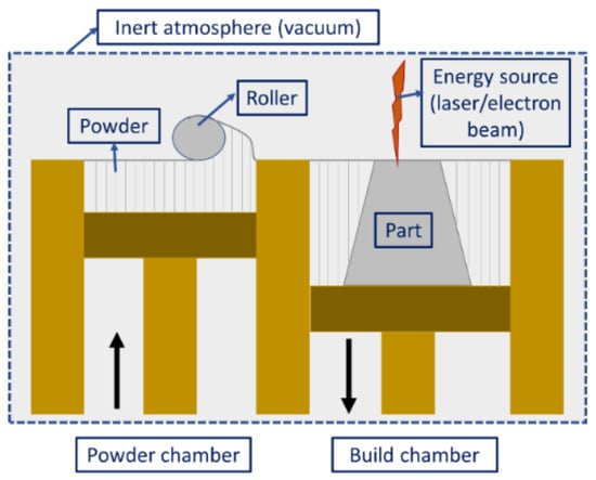
Figure 3. Schematic diagram illustrating the powder bed fusion process.
4.1.1. Laser-Based PBF
The laser PBF can be subdivided into selective laser sintering (SLS) and selective laser melting (SLM), the difference being the material preference and fusion mechanism of the powders [93]. On one hand, SLM melts the powder completely to form a homogeneous part, while SLS uses a point-based heating phenomenon and allows only molecular fusion at the surface. However, both processes can be used for coating purposes; SLM is preferred for the complete coating of surfaces whereas SLS is preferred for the localized deposition of engineering materials.Selective Laser Sintering
Selective laser sintering (SLS) is a typical AM method wherein layer-by-layer deposition takes place by spreading the powders, followed by their selective sintering. Figure 4 is a typical schematic diagram of the SLS process constituting a powder layering setup, laser source, system interface, and other accessories (i.e., preheating unit and inert gas protection system). The types of lasers used in the SLS process include Nd:YAG [94], CO2 [95], fiber lasers [96], disc lasers [97], etc. The appropriate choice of lasers affects the strengthening of the powders for the following reasons: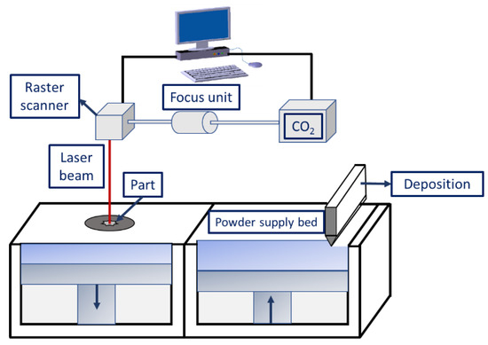
Figure 4. Schematic diagram illustrating the selective laser sintering process.
- i.
-
The laser absorptivity of the materials depends greatly on the laser wavelength.
- ii.
-
The laser power energy determines the metallurgical changes occurring during powder densification.
-
The part to be fabricated is leveled and fixed on the platform bed.
-
An inert-gas-filled atmosphere is created in the sealed building chamber to restrict the presence of oxygen during the process.
-
Layering mechanism and laser beam scans enable the deposition of a thin layer of loose powder particles on the substrate material, allowing for selective molecular diffusion.
-
The repetitive process of the above-mentioned steps helps in building the final part in a layer-by-layer fashion.
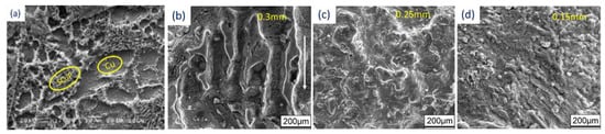 Figure 5. Scanning electron microscopy images of sintered samples prepared with (a) Cu-SCuP and (b–d) W-Cu.
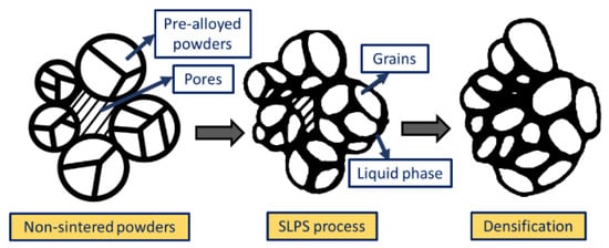 Figure 6. Schematic representation illustrating the densification process of the pre-alloyed powders during the SLPS process.
Selective Laser Melting (SLM)
The urge to obtain densified components with enhanced mechanical properties forced the research community to develop the laser melting process. The process stands out for its ability to produce parts with minimal post-processing cycles and material waste. SLM has the same procedure and apparatus as the SLS process. The only difference is that the complete melting and solidification of powders take place during the SLM process, whereas in the SLS process, just sintering takes place. The continuous improvement in the laser processing parameters, such as focused spot size, high laser power, smaller layer thickness, etc., has altered the metallurgical and mechanical properties [111]. As a result, SLM is best suited for producing parts with 99.99% relative density without any post-processing methods [112]. Li et al. [113] and Santos et al. [114] processed steel components using SLM and found that high scan speeds result in porosity in samples, along with a reduction in tensile strength. Figure 7 indicates the variation in porosity and microstructure in stainless steel samples prepared through SLM at different scanning speeds, wherein a significant difference in the morphology of the melt pool boundaries is visible.Another advancement in the SLM process is its ability to process different categories of materials such as crystalline (high-entropy alloys), quasicrystalline, and amorphous systems [115][116][117][118][119][120][121][122][123][124][125][126][127][115,116,117,118,119,120,121,122,123,124,125,126,127], which is difficult through the partial melting SLS process. The earlier attempts to process the pure metals were unsuccessful through SLS, the reason being that the high viscosity of liquid material caused a balling effect that restricted the process [128][129][128,129]. On the contrary, the product manufactured through the SLM process is denser and can be controlled as desired [130][131][130,131]. However, SLM employs higher energy, which depends on laser power, the type of laser beam, exposure time, and layer thickness. Owing to such high energy input, instability in the molten pool may be observed, leading to a high degree of shrinking and internal stresses in the final component [24][132][24,132]. The residual stresses that arise during the SLM process due to rapid cooling also cause the distortion and/or delamination of the part. In a study conducted by Pogson et al. [133], it was affirmed that the incorporation of Cu into the tool steel imparts high energy input during the SLM process. This leads to the generation of austenite grain boundaries that might lead to cracking by hot tearing. The unstable melting may result in spheroidization of the melt pool, known as the balling effect, and can cause internal porosity in the samples. Some of the defects that arise during the SLM processes are shown in Figure 8. Therefore, suitable process parameters must be chosen to yield a moderate temperature, thereby avoiding the overheating of the SLM system [134].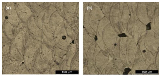 Figure 7. Microstructure showing the presence of porosity in stainless steel samples fabricated by the SLM process as a function of different laser scanning speeds: (a) 200 mm/s and (b) 400 mm/s.
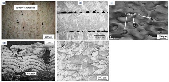 Figure 8. Defects generated during the SLM process: (a) porosity, (b) inadequate fusion between layers, (c) balling effect, (d) hot tear, and (e) fish scaling.
4.1.2. Electron-Beam-Based PBF
Electron beam powder bed fusion (E-PBF) uses a high-power electron beam to fuse metallic powder in a layer-by-layer manner into the final bulk component [93][135][136][93,139,140]. During the process, electrons emitted from the heated filament (W or LaB6) cathode are accelerated towards the substrate material at half the speed of light with 30–60 kV [137][141]. The process takes place under vacuum (He pressure < 1 Pa) to reduce the probable collision between the swift-moving electrons and the air molecules and to restrict the oxidation of metallic powders [138][139][142,143]. Electromagnetic lenses are used to focus the electron beam that can move at a deflection speed of about 10 km/s and a power of 5–10 mA, thereby allowing innovative heating and melting approaches. Once the electrons are bombarded to the powder bed, more of the kinetic energy is converted to heat energy, thus enabling local sintering of the powders. Figure 9 shows a schematic diagram of the E-PBF system. When compared to lasers, the electron beams penetrate significantly deeper (101 to 102) into the powder particles [140][144]. The powder bed is maintained at high temperatures, i.e., more than 870 K, and requires overnight cooling after job completion. E-PBF involves comparatively more processing parameters than LBPF technology. Some of the parameters include electron beam focus, power, scan speed, diameter, beam spacing, plate temperature, pre-heating temperature, contouring systems, and scan strategies [93]. The process parameter optimization is comparatively more difficult in the case of the E-PBF process than SLM; thus, only a limited number of materials can be processed through this method, i.e., CoCrMo [141][145], Ti grade 2 [142][146], Inconel-718 [143][147], Ti grade 5 [144][148], etc. The restrictions during the manufacture of intricate lattice structures (honeycomb) and low processing time make the process challenging. However, larger-sized products can be manufactured easily through this process irrespective of the substrate plate’s size. In a recent study, AlN coatings were produced over Ti6Al4V substrate through EB-PBF technology [145][149]. The authors achieved an adherent coating on the substrate without altering the core’s microstructure. The hybridization of EB-PBF with other methods such as chemical vapor deposition and atomic layer deposition allows for improved coating properties [146][147][150,151]. It is not advised to produce parts that constitute volatile components such as Mg, Zn, Bi, Pb, etc., through the E-PBF process. It is effective enough to process brittle materials, unlike SLM. The poor thermal expansion and contraction of intermetallic (brittle) materials tend to induce the formation of defects (solidification cracks) by restricting them to cool down at a slower rate. In this regard, SLM fails to slow down the cooling rate, thereby leading to crack propagation, while E-PBF allows the drop in cooling rates by increasing the temperature of the powder bed (~870 K) [148][152]. Thus, intermetallic materials such as TiAl and high-entropy alloys can be processed through the E-PBF process with careful consideration of temperature.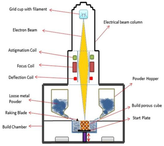 Figure 9. Schematic representation of the electron beam powder bed fusion technique.
4.2. Binder Jetting
Binder jetting is a type of AM technology that involves multiple steps for the fabrication of 3D parts. The process was introduced in the early 1990s by the Massachusetts Institute of Technology (MIT) and was commercialized in 2010 [149][154]. This technology can process almost all metals/alloys/ceramic materials (glass, graphite, sand, etc.) from powder form. The process requires a base material (metal/alloy/ceramic) of which the part is to be made, along with a binding agent (liquid phase) for gluing the material in layers. The printing technique is like any other AM printing process that takes place layer by layer. The powder (metallic/ceramic) material is spread over the bed by a roller according to a computer-aided design (CAD). The printing head allows the recurrent deposition of the binder adhesive as dictated by the CAD data over the powder bed [150][151][155,156]. As shown in Figure 10, the bed platform is adjusted or lowered based on the set layer thickness. As soon as the powder is bound to the binder adhesive, another layer of material is spread onto the previous layer, tending towards the final part. The loose powders that are unused or do not adhere to the layer surround the part until the final product is achieved.Despite the simplicity of the binder jetting process, it involves several lengthy post-processing operations, such as sintering, de-powdering, curing, annealing, infiltration, and finishing [152][153][157,158]. One major advantage of this process is that there is no need for support structures while printing parts. The built parts remain on the powder bed without being bonded to each other. Thus, the entire volume of the built part can be stacked together, with many other parts to be printed with a small gap between them [154][159]. Because of the use of adhesives, this process is not recommended for structural applications (i.e., aerospace/automotive) since it might lead to porous parts. As compared to SLM/E-PBF, the binder jetting process is faster and can be further accelerated by implementing multiple printing heads/holes for deposition. It also allows multi-material deposition to obtain desired surface properties on a single component by changing the ratios of powder to binder. Coarser powders can also be used in this process, thereby cutting the manufacturing costs of finer powder particles. One more advantage of this process is the non-involvement of heat during the deposition process, thereby eliminating the formation of residual stresses in the final part [155][160]. Since the strengthening mechanism involved in the process is due to sintering, which may account for porosities, one may obtain varying shapes, volumes, and sizes of the pores in the final batch of products [156][161]. Furthermore, the final components are prone to having a coarse microstructure because of the post-processing operations. Thus, the parts produced through binder jetting lack suitable mechanical properties.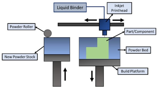 Figure 10. Schematic diagram illustrating the binder jetting process.