As the population increases, the number of motorized vehicles on the roads also increases. As the number of vehicles increases, traffic congestion occurs. Traffic lights are used at road junctions, intersections, pedestrian crossings, and other places where traffic needs to be controlled to avoid traffic chaos. Due to traffic lights installed in the city, queues of vehicles are formed on the streets for most of the day, and many problems arise because of this. One of the most important problems is that emergency vehicles, such as ambulances, fire engines, police cars, etc., cannot arrive on time despite traffic priorities. Emergency vehicles such as hospitals and police departments need to reach the scene in a very short time. Time loss is a problem that needs to be addressed, especially for emergency vehicles traveling in traffic.
- emergency vehicles
- signaling
- smart traffic lights
- smart roads
1. Introduction
2. Installation of Traffic Lights and Mobile Application
2.1. Traffic Light Materials
Arduino UNO board, four-channel 5 V relay board, SIM808 GPS/GPRS/GSM module, triple traffic lights powered by 12/24 V, 12 V adapter, 9 V adapter, and 8 V adapter, a jumper for connection cable and female and male DC power supply cables are used in the installation of traffic lights in the signaling system. The properties and intended use of the materials used are given below, respectively.2.1.1. Arduino UNO
Among Arduino boards, the most useful and well-known Arduino Uno model [26][11]. All Arduino Uno models have 14 digital inputs (D0–D13), six analog inputs (A0–A5), a USB port, and an adapter port. The original models of the board have an Atmega328p microcontroller (Figure 81).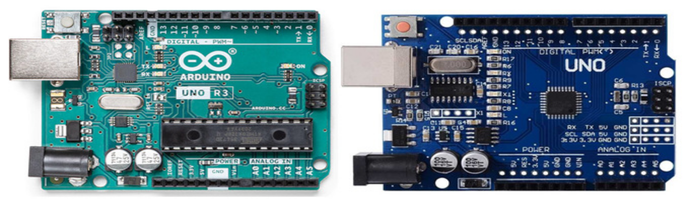
2.1.2. SIM808 GPS/GPRS/GSM Development Module
The SIM808 card is a device that can be used for data communication between cellular network systems. This module supports quad-band GSM/GPRS communication operating at frequencies of 850 MHz, 900 MHz, 1800 MHz, and 1900 MHz [28,29][13][14]. It provides ease of use in projects thanks to its small size and lightweight. There are SMA connectors on the board for antenna connections. Separate antennas must be used for GSM, GPS, and Bluetooth. To initialize the board, press and hold the “start” button for 2 s after connecting the power. The network connection status of the card can be monitored from the LEDs on the board. It has a 1.25 V, 3.3 V, and 5 V compatible TTL serial connection (UART) for connecting development boards such as Arduino and Raspberry Pi [30][15].2.1.3. Four-Channel 5 V Relay Board
A relay is a programmable electrical switch controlled by an Arduino board or any microcontroller (Figure 92). It is used to programmatically control or operate devices with high voltage and/or current. It is a bridge between Arduino and high-voltage devices [31][16]. There are three connections on the relay, usually labeled NO (normally open), NC (normally closed), and COM (common). The normally open connection is a common-ended open circuit when the relay is not energized, so no conduction occurs. When the coil of the relay is energized, the NO and COM terminals are short-circuited, allowing electric current to flow. The NC terminal works in the opposite direction to the NO terminal, i.e., when the coil is not energized, the NC and COM terminals are shorted. When energized, they form an open circuit. COM (Common) is the common input. To this input [32][17], the voltage source that the relay will switch is connected.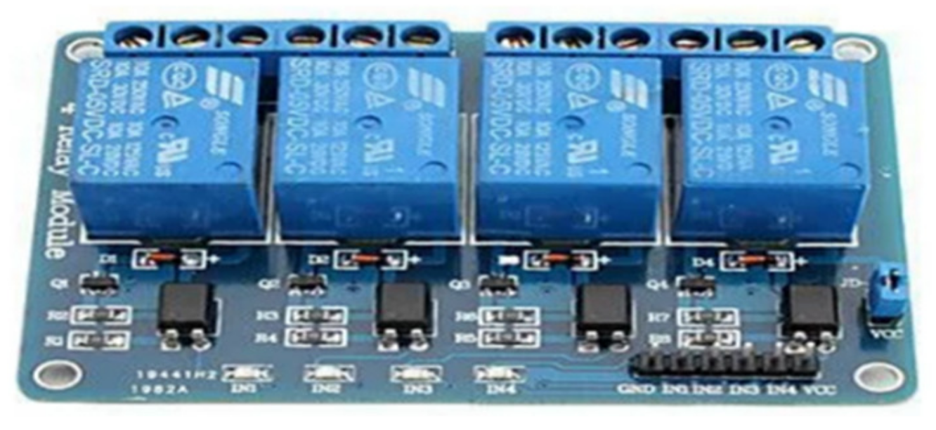
2.1.4. 12/24 V Traffic Light
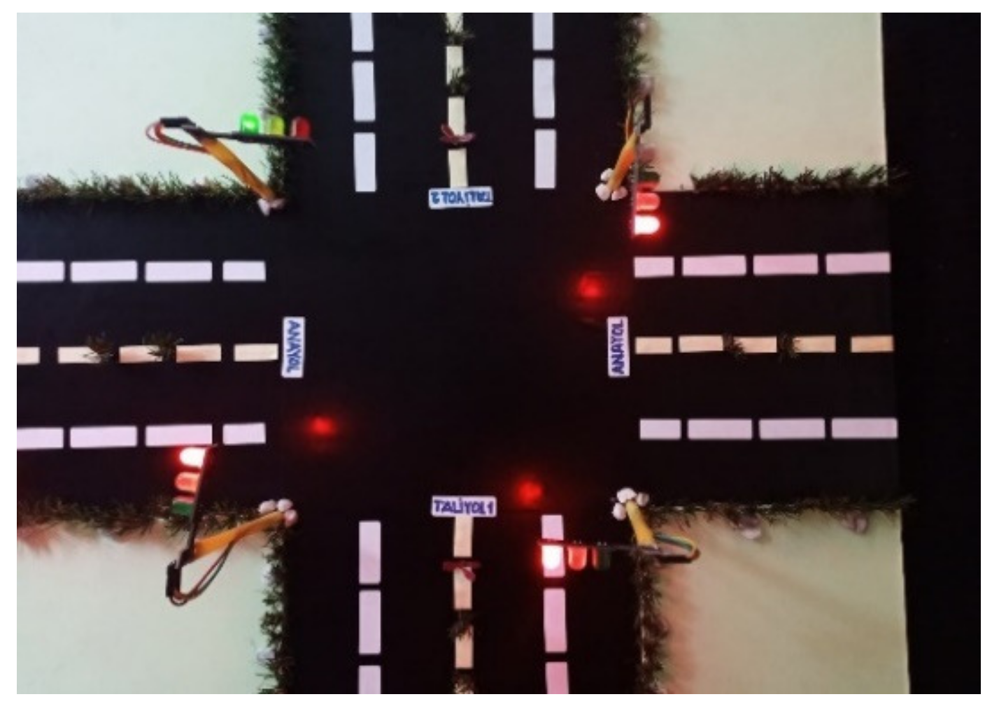
Developed in 1912, traffic lights are signaling devices designed to control traffic flow at road intersections, pedestrian crossings, railway trains, and other places. There are four different outputs in traffic lights used in signaling construction. These are the control outputs of red, yellow, and green LEDs and the ground (GND) output (Figure 103).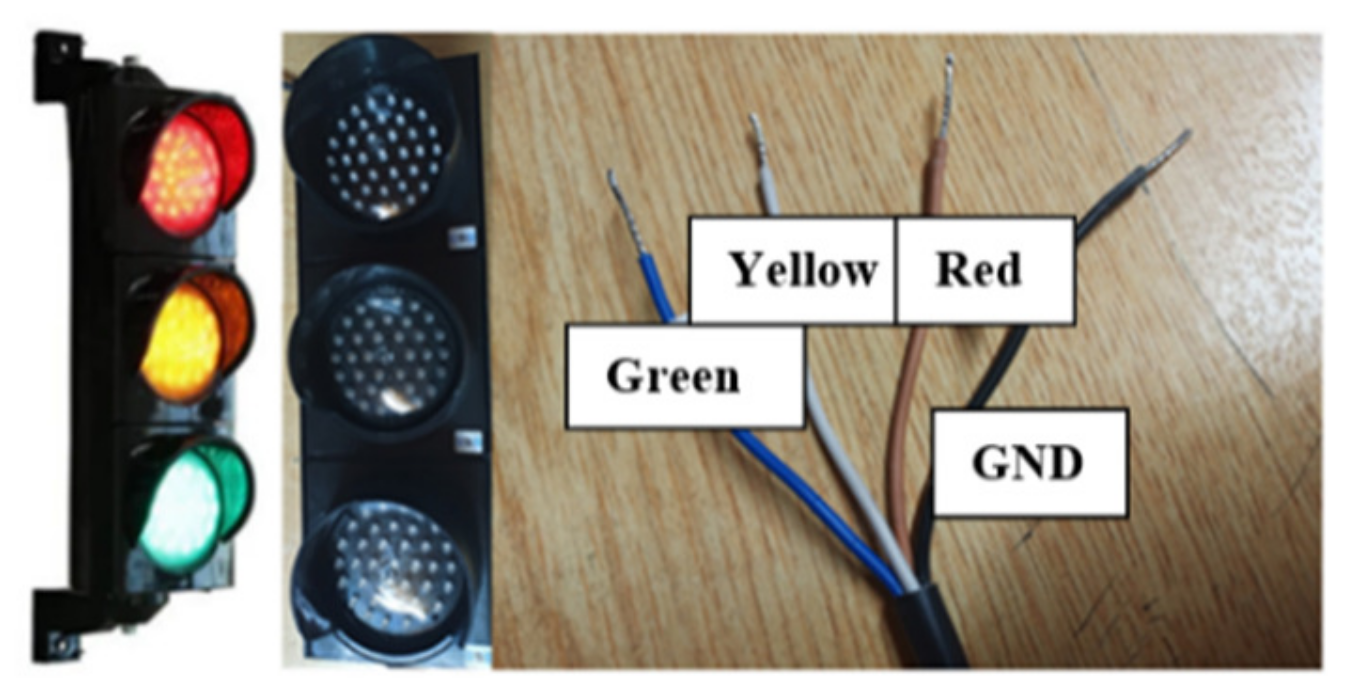
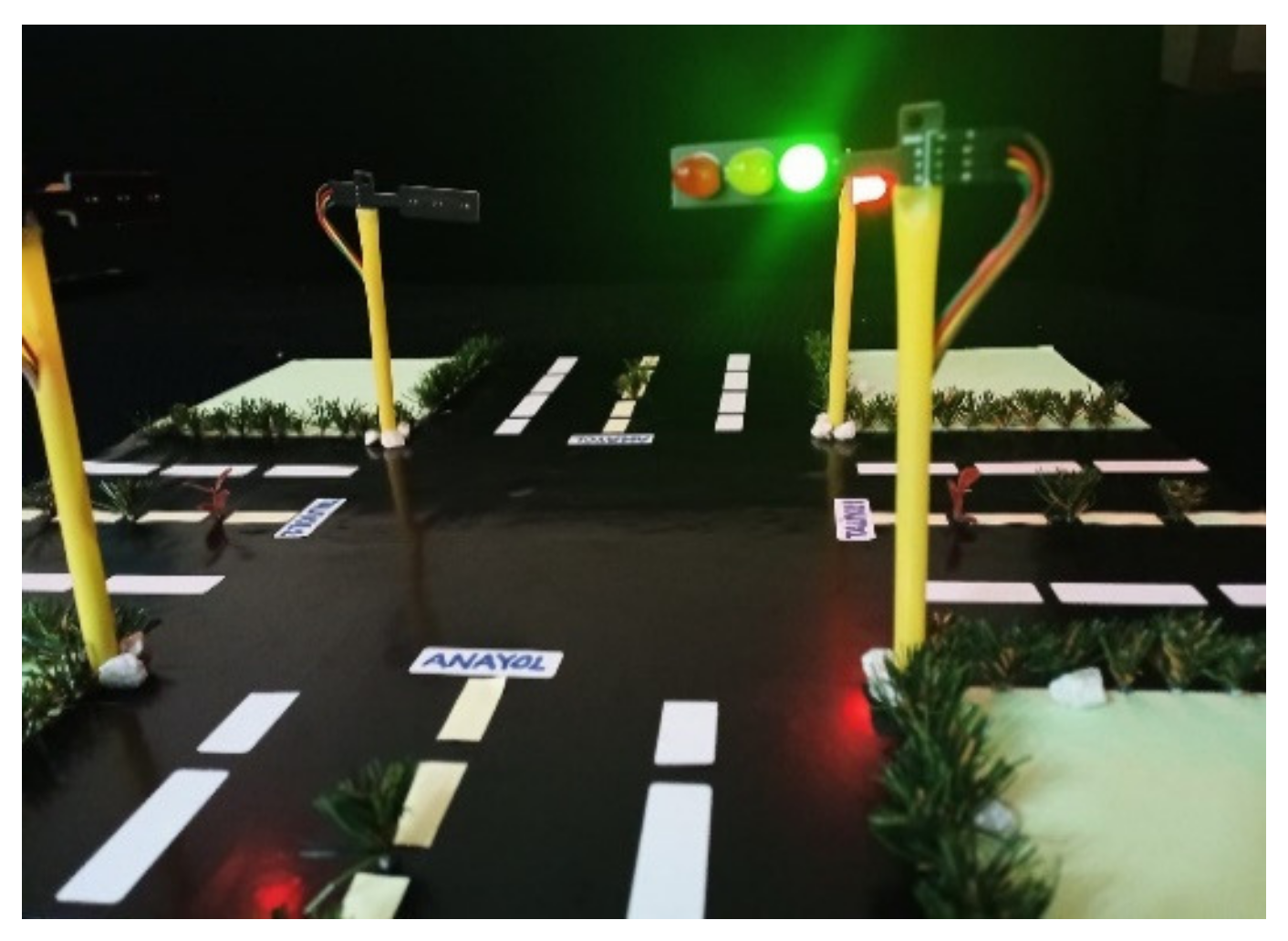
2.2. Prototype
Before the physical installation of the signaling system, a prototype of the system is created. This prototype reflects the similar operation of the real system. Errors in the software were eliminated in the trials made on the prototype. Arduino Uno, Sim808 GSM/GPRS/GPS card, and traffic light module were used to prototype the system. Since the supply voltage of the traffic light modules is 5 volts, no relay was used in the prototype. The traffic light module has three pins (red, yellow, and green) and one ground (GND) pin. A visual representation of the module is given in Figure 114.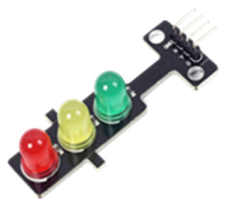
2.3. Hardware Design
Circuit designs were made using Fritzing software in the setup of the system. Fritzing is open-source software that enables the original development of electronic circuits using Arduino boards. Fritzing users can prepare prototypes of the circuits and circuit elements they develop, share them with others, and use their outputs. It is possible to use experimental circuit boards, schematics, printed circuits, and code related to Arduino in the Fritzing program. The circuit elements are divided into sections and are categorically accessible [33][18].2.3.1. Connection of Arduino UNO and SIM808 GSM/GPRS/GPS Board
When connecting the Sim808 GSM/GPRS/GPS board to Arduino UNO, the UART TTL interface on the Sim808 board is used. Three pins are used for connection in this section. These pins are RX, TX, and GND pins. A connection diagram and the actual connection are given in Figure 147.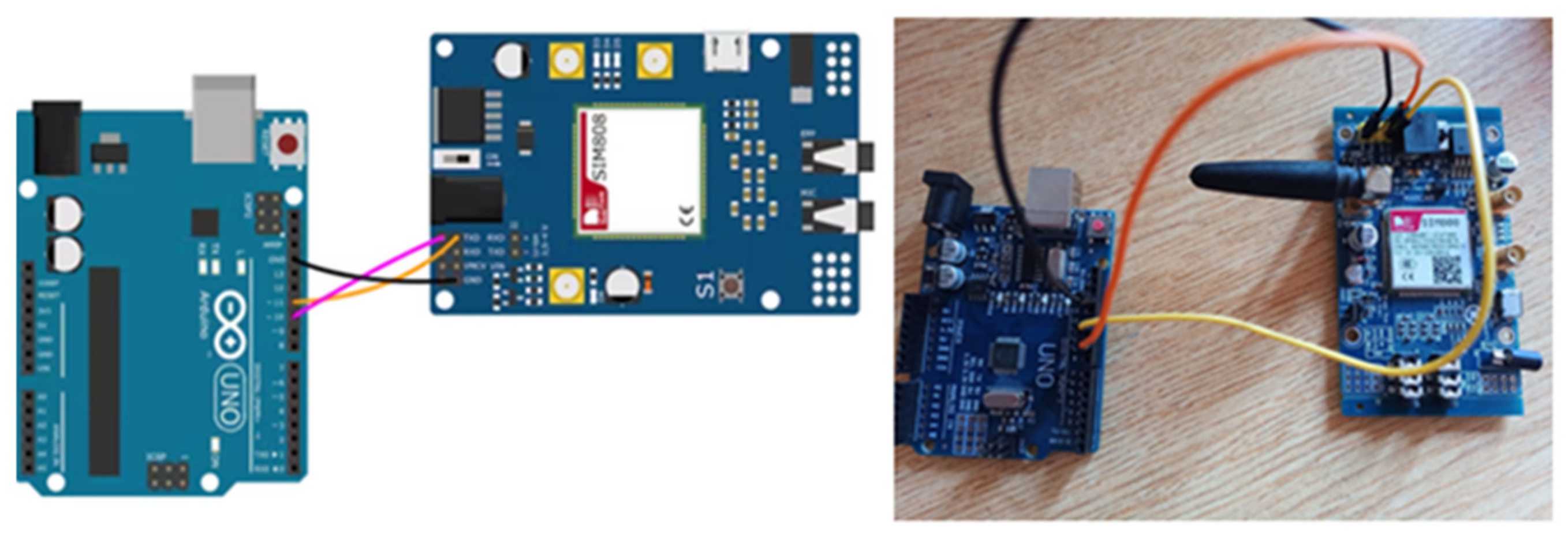
2.3.2. Connection of Relay and Traffic Lights
There are four cables in the traffic lights used in the installation of the system. Three belong to colors, and one to ground (GND). The lights work between 12 and 24 volts. Since there are three LEDs to be controlled in traffic lights, four-channel relays are used. When connecting the lights with the relay, the cables to which the LEDs are connected are connected to the NO pin of the channels on the relay. The COM pins of the relay to which the LEDs are connected are also connected to each other and connected to the power supply with the help of a terminal. The GND cable from the light is connected to the power supply used. The connection diagram is given in Figure 158.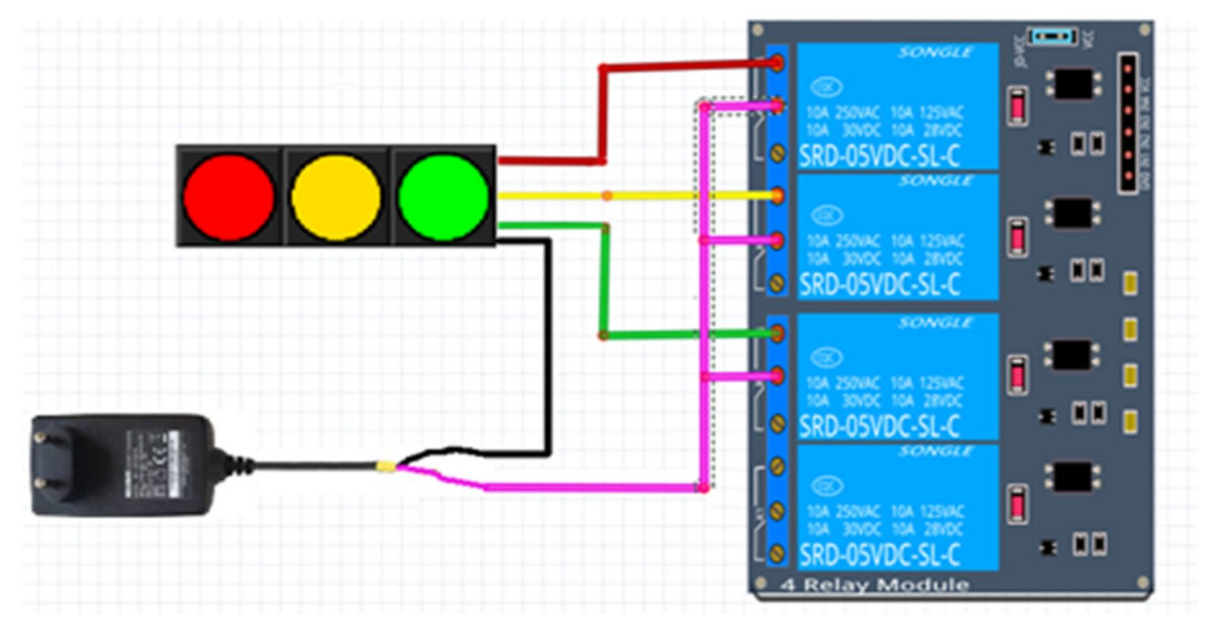
2.3.3. Arduino Uno and Relay Connection
By using a relay module with an Arduino board, it is possible to turn on and off devices operating with AC or DC voltage [34][19]. Relay modules are sold with 5 V or 12 V power supply. In this project, since a maximum of 5 volts of power can be obtained from an Arduino UNO, a relay with an operating voltage of 5 volts was used. When connecting the relay to the Arduino UNO, the VCC, GND, and signal pins on the front of the relay module are used. The 5 V relay module is powered by the 5 V pin on the Arduino UNO. At the signal end, the lights are controlled by sending a signal from Arduino UNO according to the incoming message information. The connection of the relay with Arduino UNO is given in Figure 169.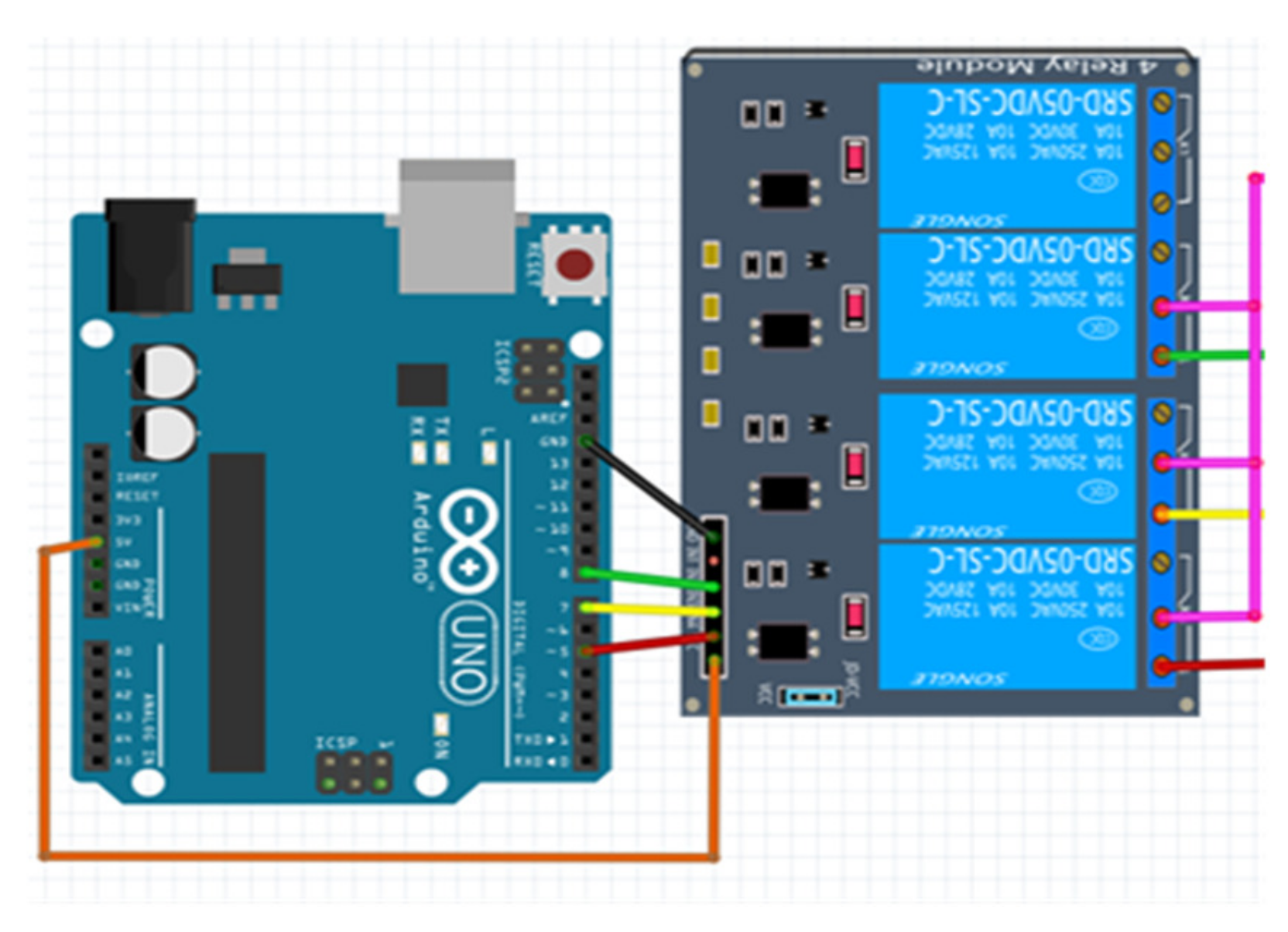
2.4. Mobile Application
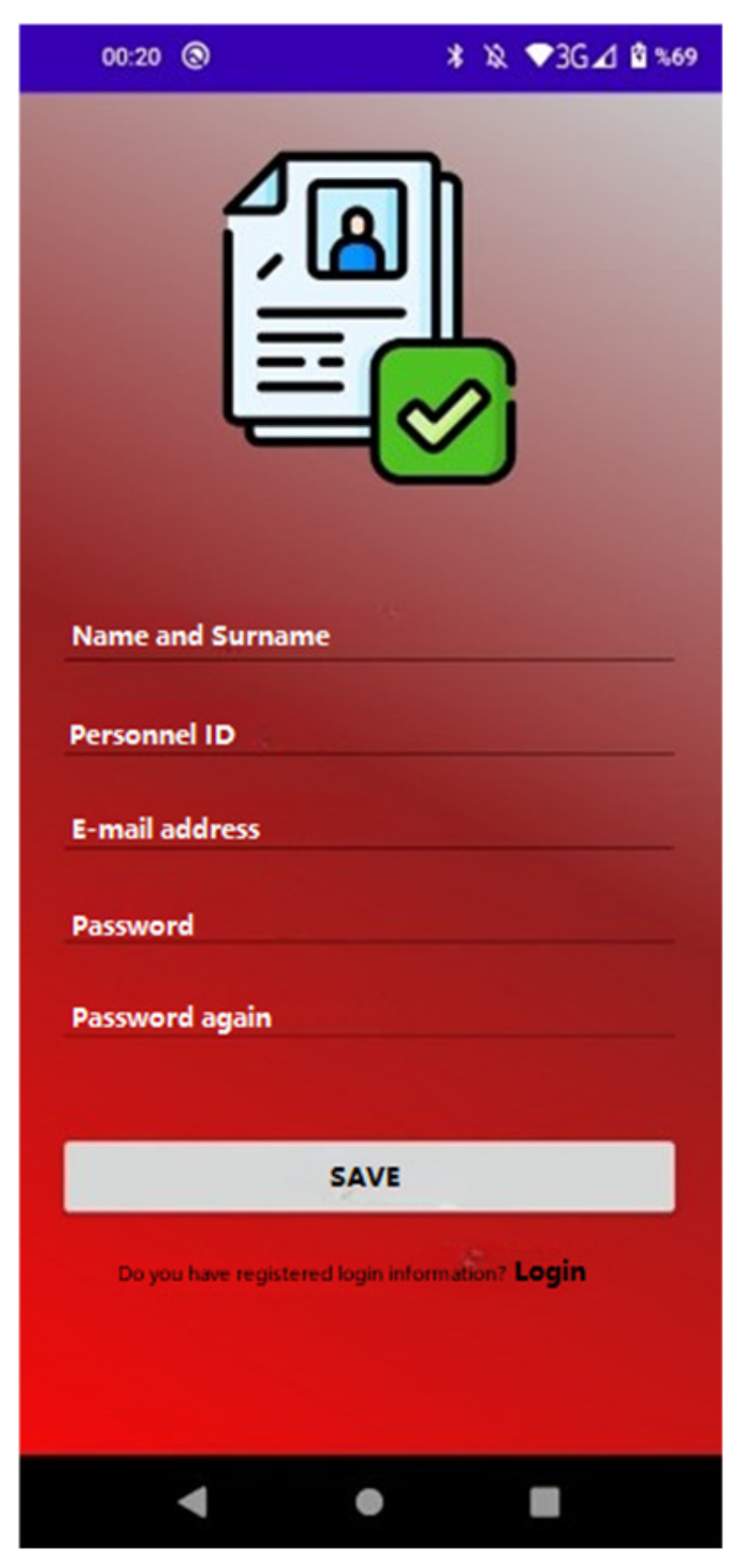
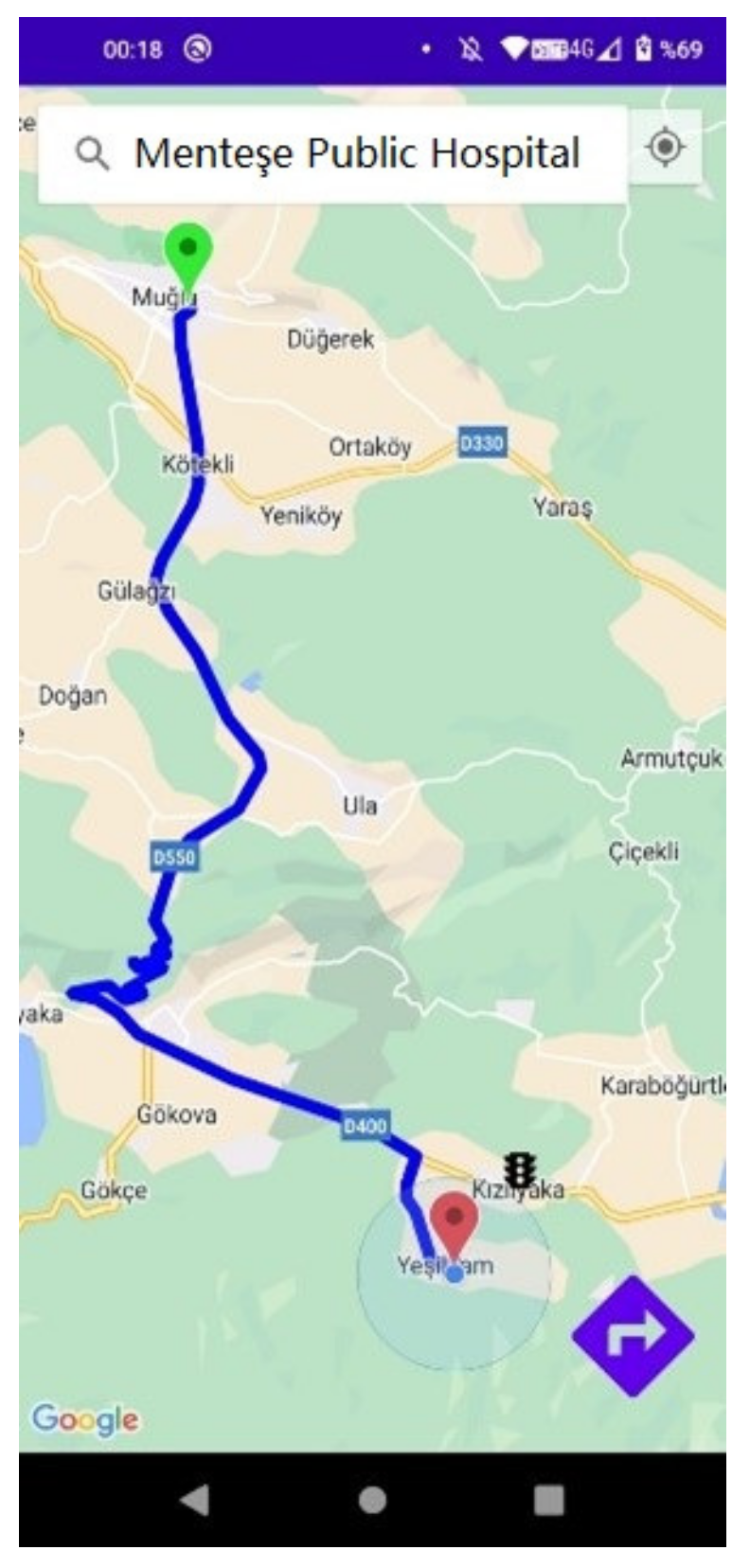
The developed mobile application is designed for the person using the emergency vehicle. The use of the application belongs only to the relevant person. The mobile application has a login screen, user registration screen, map screen, and traffic light control screen. The necessary information to access the application is given to the person using the vehicle by the organization they are affiliated with. This login information is saved in the Firebase real-time database. It is possible to create a new account by logging in from the login screen and switching to the next screen or another screen. On this screen, the person logs into the system using the ID and password information given to them or the information they create themselves. The login information of authorized personnel is previously saved in the Firebase database. The user’s login information is verified with Firebase Authentication. After the login information is verified, the message “Login Successful” appears on the screen. The login screen is given in Figure 170.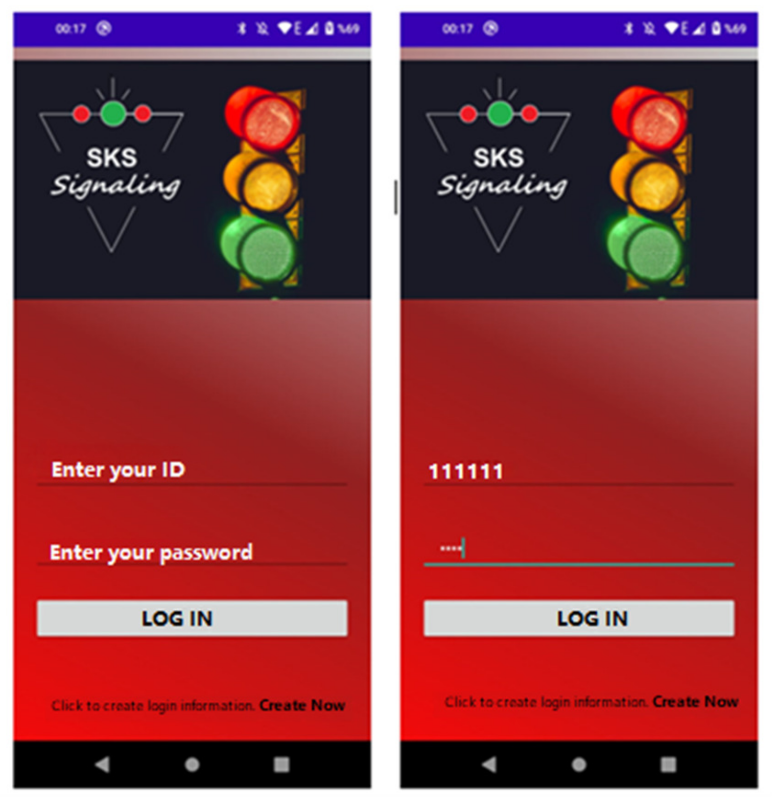
- Results and Discussion
3. Development of a Smart Signalization for Emergency Vehicles
In this section, the operation of the developed traffic lights was tested. In addition, the number of emergency vehicles passing through the signaling system, the total number of vehicles passing through the signaling system, and the distance that other vehicles should travel during the arrival of the emergency vehicle in case of failure of the developed system were determined.
Field Test
With the module installed using Arduino Uno, SD card module, DS1302 RTC module [35][20], and MZ80 infrared sensor [36][21], the number of vehicles passing through the routes determined in the field study was counted. The installed devices and their installed state are given in Figure 23 Figure 16. In the module installed for vehicle counting, the MZ80 infrared sensor is used to detect obstacles and objects in front of it. DS1302 RTC module is used to attain time information. Data obtained are written to the SD card inserted in the SD card module.
In this section, the vehicles used in the existing signaling system are examined in order to study the operation of the signalization system installed in the field test in Mugla˘ province of Turkey. Investigations were carried out on the Mugla˘-Fethiye and Fethiye-Mugla˘ routes of Mu˘gla Province, including the signalized intersection shown in Figures 24 Figures 17 and 2518.
Figure 2316.
Vehicle counter modules.
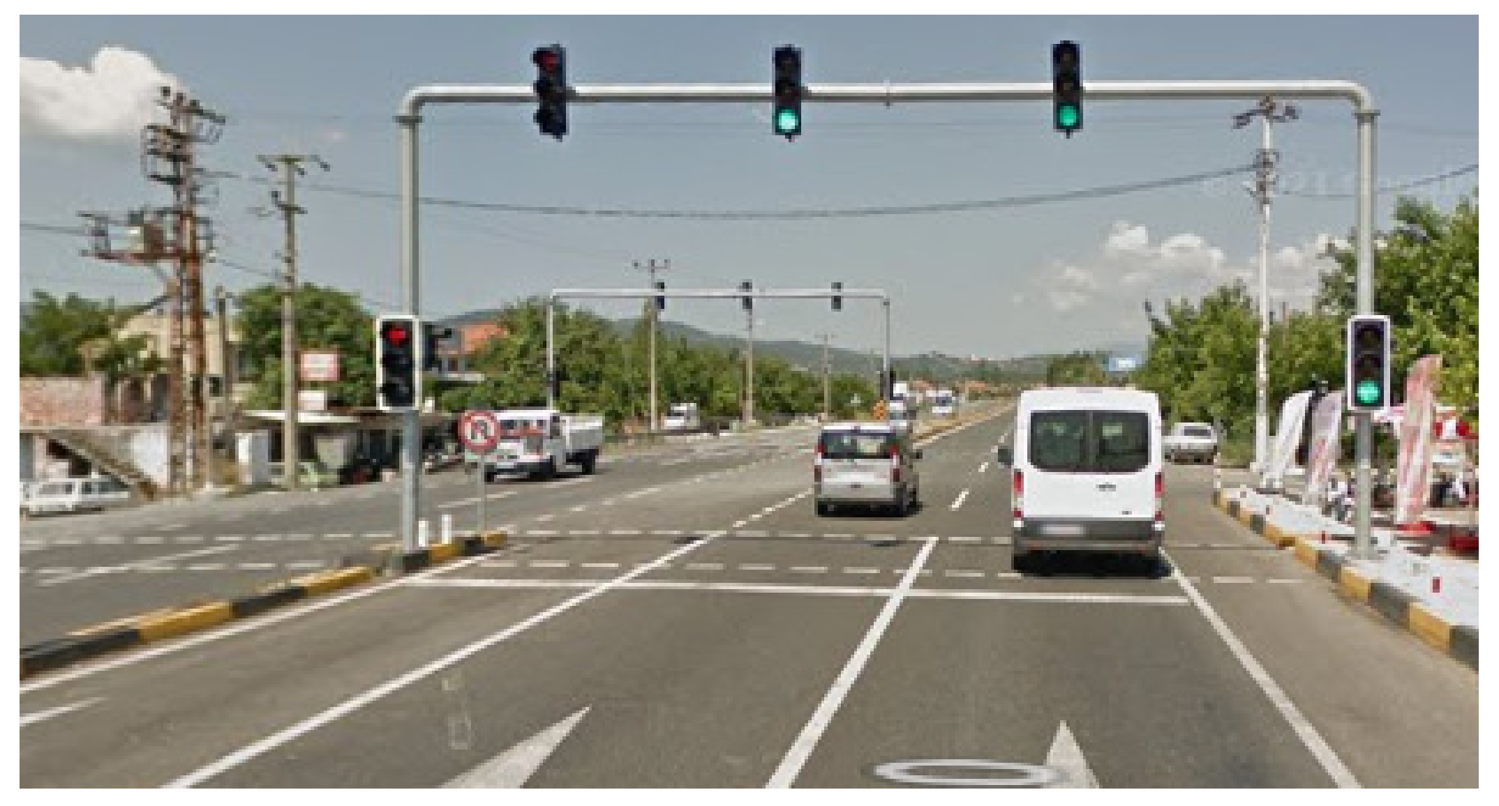
Figure 2417.
Mugla-Fethiye route.
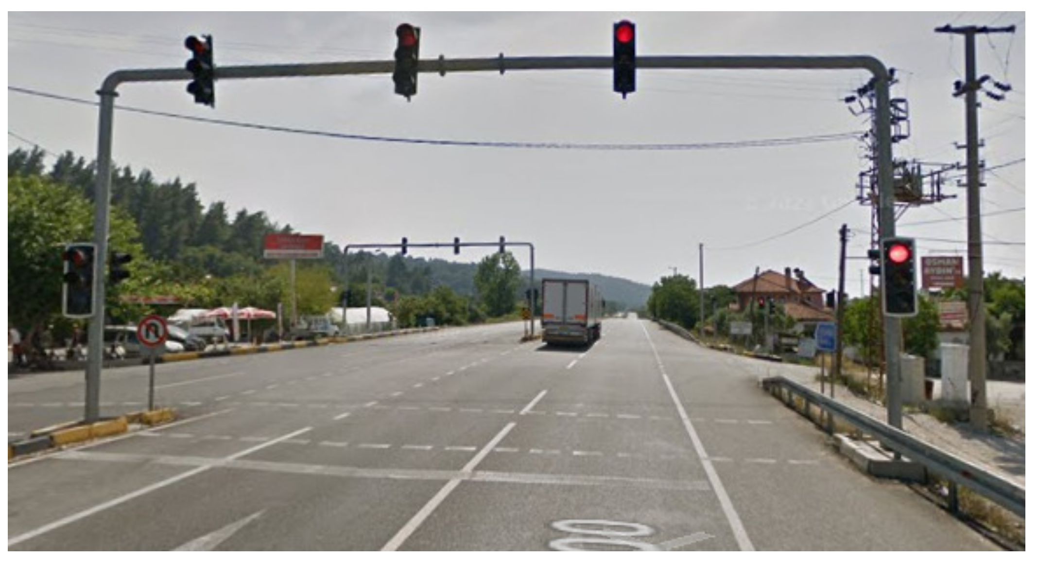
Figure 2518.
Fethiye-Mugla route.
The field tests were carried out on Thursday between 08:30 and 10:30 on the busiest day of the week. Data obtained during these hours are given in Table 2Table 1.
Table 21. Field test data.
Field test data.
| Route | Total Number of Passing Vehicles | Total Number of Emergency Vehicles Passed |
|---|---|---|
| Muğla-Fethiye | 550 | Ambulance:1 |
| Fethiye-Muğla | 611 | Ambulance:3 Police:2 Firefighter:1 |
References
- Khan, F.; Zahid, M.; Gürüler, H.; Tarımer, İ.; Whangbo, T. An Efficient and Reliable Multicasting for Smart Cities. CMC Comput. Mater. Contin. 2022, 72, 663–678.
- Khan, F.; Khan, A.W.; Shah, K.; Qasim, I.; Habib, A. An algorithmic approach for core election in mobile ad-hoc network. J. Internet Technol. 2019, 20, 1099–1111.
- Khan, F.; Abbas, S.; Khan, S. An efficient and reliable core-assisted multicast routing protocol in mobile Ad-Hoc network. Int. J. Adv. Comput. Sci. Appl. 2016, 7, 231–242.
- Abbas, S.; Talib, M.A.; Ahmed, A.; Khan, F.; Ahmad, S.; Kim, D.H. Blockchain-based authentication in Internet of vehicles: A survey. Sensors 2021, 21, 7927.
- Öztürk, N.B. Smart Traffic Systems. Master’s Thesis, University of Sakarya, Sakarya, Turkey, 2006.
- Gonca, C.K.; Gülsün, B. Adaptive traffic management systems. OHS Acad. J. Occup. Health Saf. Acad. 2019, 2, 32–40.
- Dağüstü, H.Ş. A signal Timing Model for the Control of Intersection Traffic in Traffic Management. Master’s Thesis, Yıldız Technical University, Istanbul, Türkiye, 2010.
- Karaoğlan, M.E. Optimization at Coordinated Signalized Intersections. Master’s Thesis, Pamukkale University, Denizli, Türkiye, 2021.
- Murat, Y.Ş. Computer Examination of Traffic Flows at Denizli City Intersections. Master’s Thesis, Pamukkale University, Denizli, Türkiye, 1996.
- Özkaya, U.; Seyfi, L. A novel fuzzy logic model for intelligent traffic systems. Electron. World 2016, 122, 36–39.
- Aksu, C. Multifunctional Robot Powered by Arduino. Master’s Thesis, Haliç University, Istanbul, Türkiye, 2020.
- Available online: https://www.robotiksistem.com/arduino_uno_ozellikleri.html (accessed on 6 January 2023).
- Desai, M.; Phadke, A. Internet of things based vehicle monitoring system. In Proceedings of the International Conference on Wireless and Optical Communications Networks (WOCN), Mumbai, India, 24–26 February 2017; pp. 1–3.
- Najmurrokhman, A.; Daelami, A.; Komarudin, U.; Imanudin, M. Design and implementation of vehicle speed recorder using GPS tracker and internet of things platform. In Proceedings of the 2021 International Conference on Artificial Intelligence and Computer Science Technology (ICAICST), Yogyakarta, Indonesia, 29–30 June 2021; pp. 152–156.
- Available online: https://www.robotistan.com/sim808-gsmgprsgps-gelistirme-karti-arduino-ve-raspberrypi-uyumlu-7381 (accessed on 6 January 2023).
- Available online: https://www.hbmacit.com/2020/01/09/arduino-ile-role-kullanimi/ (accessed on 6 January 2023).
- Available online: https://maker.robotistan.com/role-nedir/ (accessed on 6 January 2023).
- Ocak, M.A.; Efe, A.A. Coding and Microcontroller Applications with Arduino, 1st ed.; Anı Publishing: Ankara, Turkey, 2018; 616p.
- Satapathy, L.M.; Bastia, S.K.; Mohanty, N. Arduino based home automation using Internet of Things (IoT). Int. J. Pure Appl. Math. 2018, 118, 769–778.
- Yeni, N.; Ordu, Ş.; Karakulak, E.; Mutlu, R. Temperature and conductivity measurement of Çorlu stream with microcontroller based circuit and its transmission via gsm. Trak. Univ. J. Eng. Sci. 2022, 23, 63–71.
- Turan, S. Design and implementation of a robot detecting obstacles and going between lines for electric powered wheelchair. Gaziosmanpasa J. Sci. Res. 2017, 6, 21–29.