Carbon nanotubes (CNTs) are promising nanomaterials that are attractive components in composite solder applications due to their excellent mechanical, electrical, and thermal properties
[1][2][11,12]. The mechanical properties of composite solders have been significantly improved by using CNTs
[3][4][13,14]. In CNT-based composite solders, CNTs can be roughly divided into unmodified CNTs and metal-modified CNTs
[5][6][15,16]. The following main processing methods have been widely used to combine CNTs and solders: mechanical mixing, powder metallurgy (P/M), and electrochemical deposition
[7][8][9][17,18,19]. The former two are to mix CNTs directly with solder by physical means, and the latter is to deposit and embed CNTs in the solder matrix by chemical means.
2. Structure of CNT Composite Solder
In general, it is difficult to directly observe the structure of CNTs in composite solders due to the small amount of CNTs added. Most studies reported the structure before CNTs were added to the solder, as shown in
Figure 1 [10][22], while few studies reported the structure after CNTs were added to the solder. Considering that agglomeration is easy to cause crack initiation, theoretically, the structure of CNTs in solder can be indirectly observed on the fracture surface.
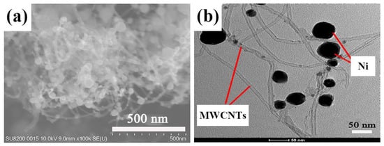
Figure 1. (
a) Scanning electron microscopy image and (
b) transmission electron microscope image of Ni-decorated multi-walled carbon nanotubes (Ni-MWCNTs) before solder addition
[10][22]. Copyright 2022 by Liu, X.; Lu, G.; Ji, Z.; Wei, F.; Yao, C.; Wang, J. Copyright under the terms and conditions of the Creative Commons Attribution (CC BY) license (
https://creativecommons.org/licenses/by/4.0/, acccessed on 3 April 2023).
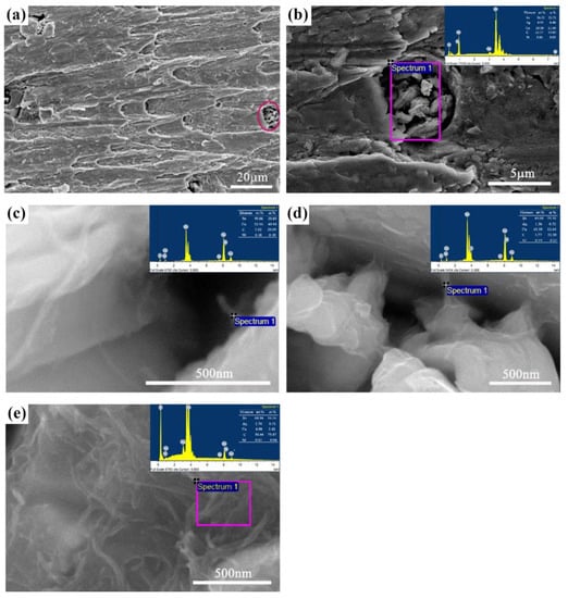
Figure 2 [11][23] depicts the fracture morphology of Sn-3.0Ag-0.5Cu (SAC305) composite solder joints containing 0.5 wt.% Ni-modified carbon nanotubes (Ni-CNTs) aged for 96 h. Enlarge the dimple circled by the purple ellipse on the right side of
Figure 2a and perform energy-dispersive X-ray spectroscopy analysis, as shown in
Figure 2b. The presence of Ni-CNTs was observed. The selected area is further enlarged, and the morphology of Ni-CNTs is shown in
Figure 2c, where it can be seen that although the Ni-CNTs have been fractured, one end is still embedded in the solder matrix. There are also some Ni-CNTs that still serve as bridges to connect the separated parts into a whole after the composite solder joint breaks, as shown in
Figure 2d. It can be seen from
Figure 2e that the structure of Ni-CNTs in the composite solder has not changed significantly. However, the Ni-CNTs are entangled haphazardly, which indicates that fractures tend to occur where there are agglomerates. The above is because CNTs are embedded in the solder matrix, so CNTs may be observed at the fracture surface. If, as shown in
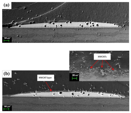
Figure 3 [12][24], a large number of multi-walled carbon nanotubes (MWCNTs) are discharged to the solder surface due to their low density during the reflow process, it is not necessarily possible to find the presence of MWCNTs on the fracture surface.
Figure 2. Fracture surface of Sn-3.0Ag-0.5Cu (SAC305) composite solder joints containing 0.5 wt.% Ni-modified carbon nanotubes (Ni-CNTs) aged at 170 °C for 96 h: (
a) macroscopic photo, (
b) magnification of the circle in (
a), and (
c–
e) micrographs of different types of CNTs appearing in the magnified rectangle of (
b)
[11][23]. Copyright Springer Nature BV Publisher, 2022.
Figure 3. Micrographs of (
a) SAC305 without layer formation and (
b) SAC305-0.04MWCNTs covered by MWCNT layer formation on top of the solder bump
[12][24]. Copyright 2021 by Ismail, N.; Jalar, A.; Afdzaluddin, A.; Bakar, M.A. Copyright under the terms of the Creative Commons Attribution 4.0 License (
https://creativecommons.org/licenses/by/4.0/, acccessed on 3 April 2023).
3. Strengthening Mechanism of CNT Composite Solder
The use of CNTs to enhance solder has become a research hotspot. It is essential to understand their strengthening mechanisms to facilitate the development of CNT composite solders. So far, many strengthening mechanisms of CNTs have been reported, and the widely accepted ones mainly include the following four
[13][14][15][25,26,27]: (1) load transfer strengthening; (2) dislocation interference strengthening (Orowan strengthening); (3) mismatch strengthening; and (4) fine grain strengthening. These mechanisms synergistically reinforce the matrix
[16][28].
First, load transfer means that when the composite solder is loaded, the interfacial stress will be transferred to the CNTs dispersed in the matrix. Due to the excellent mechanical properties of CNTs, they can bear most of the stress. Ismail et al.
[17][29] explained this mechanism through experimental results, showing that adding CNTs prevents sudden changes in the deformation mechanism in solder under shock waves. Compared with the SAC305 solder joints of the explosion test samples and the control samples, the indentation depth displacements of the SAC305-CNTs solder joints of the explosion test samples and the control samples were reduced by about 42% and 56%, respectively. The load transfer effect of CNTs was also reflected in the finite element simulation results, as the location of maximum stress intensity was shifted from the solder at the interface edge to the CNTs
[18][30]. Additionally, the interfacial bonding strength between CNTs and the solder matrix is crucial to load transfer strengthening. Literature studies have shown that the load cannot be transferred from the Sn-3.5Ag-0.7Cu (SAC357) solder matrix to Ni-modified multi-walled carbon nanotubes (Ni-MWCNTs) when the interfacial bonding strength is insufficient
[19][31].
Second, CNTs are inert materials that do not react with elements in the solder matrix and have a melting point much higher than the soldering temperature
[20][21][32,33]. Thus, CNTs can function as pinning sites. It has been reported that the yield strength of the composite solder was increased by 17.52% compared with the original Sn-0.7Cu solder when Ni-CNTs were added in an amount of 0.075 wt.%
[22][34]. This is because when the addition amount is less than 0.075 wt.%, Ni-CNTs are dispersed in the solder as the second phase, effectively hindering the movement of dislocations.
Third, the thermal modulus, elastic modulus, or geometric mismatch between the solder matrix and the reinforcement CNTs can induce plastic deformation, making dislocations multiply. Nai et al.
[23][35] showed that the high dislocation density in the matrix could be attributed to the significant difference in thermal expansion coefficient between SAC357 solder and MWCNTs. They also expressed similar views in other research results, arguing that the geometrically necessary dislocations are generated to accommodate the thermal elastic modulus mismatch between solder and MWCNTs
[24][36].
Finally, CNTs are usually dispersed at grain boundaries in the solder matrix, inhibiting grain growth. As a result, the number of grains per unit volume increases, the stress concentration decreases when a force is applied, and the grain boundary area increases, hindering the movement of dislocations
[25][37]. According to the study by Zhu et al.
[26][38], MWCNTs refine the microstructure of the composite solder and increase the grain boundary density. Therefore, the movement of dislocations is hindered microscopically, and the shear strength and hardness are improved macroscopically. However, due to the limitation of the amount of addition, the degree of grain refinement is limited. Compared with the initial solder, the average grain size of the SAC357 composite solder decreased by 6% under the influence of 0.1 wt.% Ni-MWCNTs and only 4.6% under the influence of 0.1 wt.% unmodified MWCNTs
[27][39].