Your browser does not fully support modern features. Please upgrade for a smoother experience.
Please note this is a comparison between Version 2 by Conner Chen and Version 3 by Conner Chen.
Design and analysis of power electronic converters is an integral aspect of light electric vehicle (LEV) chargers. In this respect, researchers have proposed novel DC-DC converter topologies with optimized active and passive component count. Isolated DC-DC converters are preferred for chargers with higher power ratings. They provide galvanic isolation between the input and output stage by using a high frequency transformer.
- light electric vehicle
- DC-DC converter
- on-board charger
1. On-Board Charging
On-board charging remains the most widespread charging method for light electric vehicles (LEVs), mainly in part due to its simplicity in size and source availability. In a conventional AC-based LEV charging system, there are two stages: AC-DC rectification, followed by a DC-DC PFC stage to ensure smooth input current waveform, and another DC-DC converter to control the battery charging process. However, apart from two-stage LEV chargers, researchers have also reported on single-stage LEV chargers, where a single DC-DC converter is responsible for PFC and control of battery charging [1][2].
On-board chargers can exist on the vehicle itself or may be formed as part of the charging cable. Hence, a design objective of on-board chargers is to make it more compact, and hence increase its power density. This ensures that the charger module occupies minimum space on-board the vehicle. Other desirable operational characteristics of on-board LEV chargers are high charging efficiency, high power density and an acceptable input power factor.
2. Isolated DC-DC Converter Topologies
In LEV chargers, isolation can be achieved either by use of a transformer at the supply end or within the converter itself. The supply side transformer option is not feasible, as it requires the installation of a line frequency transformer, which has a bulky design. Hence, in subsequent topologies, researchers have employed high frequency transformers in charging converter design owing to their compact size. The provision of isolation in converters is advantageous in the following ways:
- There is the obvious advantage of galvanic isolation between the battery circuit and supply, thus ensuring user safety.
- The turns ratio of the high frequency transformer may be leveraged to achieve a wider voltage gain range, thus making the converter suitable for usage with a wider load range.
The conventional on-board LEV charger topology with front-end diode bridge rectifier (DBR) remains popular among researchers. For example, Singh et al. [3] presented a topology which used an interleaved canonical switching cell (CSC) at the front-end in conjunction with diode bridge rectifier for AC-DC conversion and power factor correction. This is further cascaded with an isolated Cuk converter at the back-end. This configuration exhibits simple control and is capable of charging batteries with voltages ranging from 24 V to 72 V. The circuit diagram for this circuit is shown in Figure 1. The CSC-based PFC ensures high power factor. The CSC is interleaved to reduce the size of filters and current ripples, and operates in discontinuous mode, which reduces the volume of magnetic components in the circuit, thus making it more compact. The back end Cuk converter operates in continuous mode, which reduces charging current ripples. The Cuk converter also allows for wide voltage gain variation and demonstrates robust performance in the event of supply voltage disturbances and varying battery voltages. However, the efficiency data in these contents are missing.
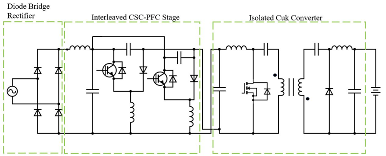
Figure 1. Isolated Cuk converter with canonical switching cell PFC [3].
In yet another example, [4] presented an LEV charger which used a simple diode bridge rectifier in the front-end and an isolated SEPIC converter in the back-end. The charger schematic for this design is shown in Figure 2. The SEPIC converter has multiple benefits over the previously described Cuk converter, such as less susceptibility to EMI and inherent current limiting capability at the time of overload/startup. To reduce the size of magnetic components, this charger operates in discontinuous mode. Furthermore, the converter demonstrated satisfactory dynamic performance and posed minimum impact on supply power quality even during varying supply voltages, in compliance with guidelines set in the IEC 61000-3-2 standard. A charging current of approximately 20 A is observed and converter efficiency is approximately 80%. Furthermore, the input inductor of the SEPIC stage aided in power factor correction.
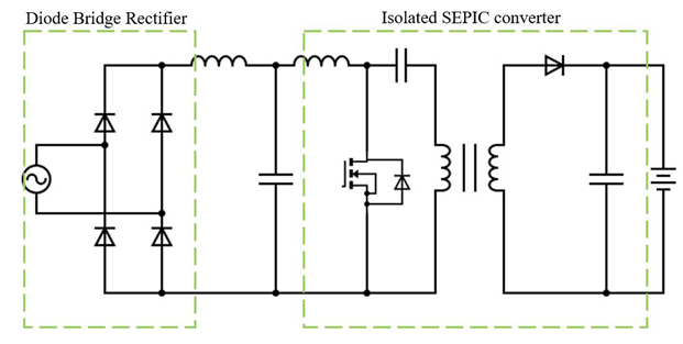
Figure 2. Isolated SEPIC converter with DBR back end [4].
The authors of [5] proposed a two-stage converter which uses a combination of Zeta-SEPIC converter as the PFC stage, followed by a flyback converter stage, which controls the battery charging process. Furthermore, the Zeta and SEPIC converter combination controls the voltage of input DC link voltage of the flyback converter. The circuit diagram of this converter is shown in Figure 3. The Zeta and SEPIC converters operate independently in the positive and negative half cycle of the input AC voltage, and both operate in discontinuous conduction mode. The Zeta and SEPIC converters are chosen for this topology due to their comparatively better ripple current suppression capability. Furthermore, there is also a reduced number of active components, which helps in the reduction in conduction losses. However, the use of DC link capacitor with a voltage of 300 V may make the circuit bulkier. Additionally, the leakage inductance of the transformer may necessitate the use of an appropriate clamping circuit across the switch. A similar topology was presented in [6], which used a bridgeless modified Landsman converter instead of the Zeta-SEPIC stage. Yet another variant of [6]—described in [7]—used an interleaved Landsman converter, which resulted in a lower input current ripple.
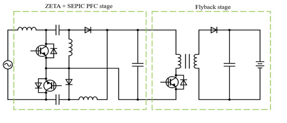
Figure 3. Flyback converter with Zeta-SEPIC PFC stage [5].
To reduce the number of semiconductor devices in charger topologies, researchers have looked to bridgeless converter topologies [8][9]. For example, the authors in [9] presented a single stage bridgeless isolated positive output Luo converter for LEV charging. This charger works for an AC input range of 85–265 V and ensures front-end high-power factor through use of Luo converter-based AC-DC converter topology. Eliminating the front-end diode bridge rectifier stage helps reduce component count and simplify design. Furthermore, the Luo converter-based topology achieves positive output polarity, which is contrary to prior implementations, which retained the negative output polarity. The significance of this feature is that this helps simplify output sensor design. Furthermore, the circuit operates in discontinuous mode to reduce magnetic component volume. This also reduces the switching/conduction losses of the switches in the circuit. The converter topology is shown in Figure 4. The authors of [10] use a bridgeless isolated Zeta converter shown in Figure 5, which also operates as a PFC converter, to charge LEVs. This on-board charger is further supplemented by a Cuk converter, which feeds solar photovoltaic (PV) power. This Cuk converter is controlled using the PV’s maximum power point algorithm. The high frequency transformer ensures a high voltage conversion ratio. Furthermore, the isolation design choice in this case is desirable to reduce ripples. However, while this design uses a smaller number of switches, its drawback is that the Cuk converter control does not depend on the battery status. Furthermore, the behavior of switches during switching operation is not elaborated in these contents.
Figure 4. Bridgeless positive output Luo converter [9].
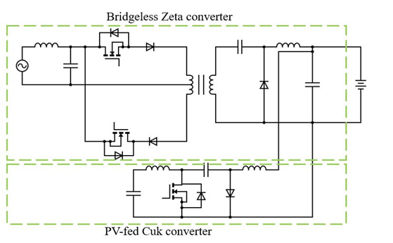
Figure 5. Bridgeless isolated Zeta converter with PV-fed Cuk converter [10].
All the bridgeless converter topologies described above [5][8][9][10][11] also ensure improved power quality by reducing the THD of the supply current. This is done by the use of input inductance, which helps smooth the input current profile. Likewise, an output inductance is also incorporated in both circuits to reduce output current ripples. It is found through experimental results that the input current THD in these demonstrations is compliant with the IEEE-519 specified threshold of 5%. Furthermore, these bridgeless topologies have the advantage of reducing conductions losses (due to reduction in the number of semiconductor devices in the current path). Bridgeless converter topologies also exhibit poor performance related to EMI, as they have the tendency to introduce common mode noise on account of the presence of high frequency switch mode voltage [12]. This can result in degradation of supply current due to high ripples. Furthermore, because of the reduced switch count, the remaining switches of the bridgeless stage are subjected to high current stresses. For these reasons, research on two-stage converter topologies continues, owing to their improved EMI performance and manageable stresses on devices.
However, lack of soft-switching techniques in the topologies described above is a limitation. This may limit its operation at higher frequencies due to higher switching losses. To overcome this limitation, resonant converter topologies have been incorporated by researchers into on-board chargers [13][14][15][16][17][18][19]. This technique has been employed for numerous on-board chargers in conventional EVs [18]. For example, authors in [13][19] presented a two-stage e-bike charger; this charger uses a Cuk converter as the PFC stage, which is followed by a half bridge LLC (inductor-inductor-capacitor) series resonant converter, which controls the battery charging process. This charger ensures a wide output voltage range through variable DC link voltage control. The Cuk converter is chosen for the PFC stage due to its inherent input ripple current rejection capability. The circuit diagram for this configuration is shown in Figure 6. While the use of a half-bridge LLC converter helps in reducing the switching losses through zero voltage switching (ZVS), there is a drawback of increased component count in this circuit. Another recent implementation of a soft switched LEV charger is described in [14]. In their work, an LLC resonant full bridge converter is used, as shown in Figure 7. This configuration uses the resonant inductance of the transformer as a resonance circuit element, and the switching frequency is kept close to the resonant frequency, thus ensuring ZVS of the semiconductor devices. While a satisfactory efficiency of 96.4% is achieved, the component count of this configuration is on the higher side. A similar efficiency of 96% is achieved in [15], which uses a two-stage converter; the first stage is an interleaved buck-boost stage and the second is an isolated half-bridge LLC stage with synchronous rectification. The resonant capacitor size is reduced by using a split capacitor structure. The interleaved stage achieves natural PFC through operation in discontinuous mode, and the LLC stage helps achieve soft switching. The LLC stage is unregulated, thus reducing control complexity.
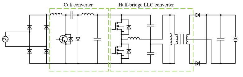
Figure 6. Two-stage charger with Cuk converter front-end and half-bridge LLC back-end [13].
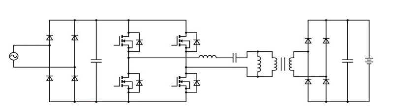
Figure 7. Full bridge LLC converter [14].
Another popular technique of modifying basic DC-DC converter-based LEV chargers comes in the form of interleaving. Interleaving—or multi-phasing—is a technique where multiple converter circuits are connected in parallel and turning on/off their respective switches after a phase delay as shown in (1) [20].
ϕ = 180/n
Here, ϕ denotes the phase delay (in degrees) and n is the number of phases connected in parallel. This process also tends to reduce the output current ripples. Another advantage of interleaving is that it increases the power handling capacity of the converter, thus lending itself to high current applications.
Authors in [21] demonstrate an interleaved isolated Luo converter, which is also capable of bidirectional power transfer. The front-end comprises a voltage source converter, which interfaces with the AC grid via an LCL filter. The back end comprises the proposed interleaved isolated Luo DC-DC converter, which operates with high efficiency at light load. The schematic for this charger is shown in Figure 8a. The system control design is performed so that there is a provision for fast charging, slow charging, and discharging (bidirectional) operations. A 40 A/20 A charging current is ensured for fast/slow charging of the LEV. Discharging mode is enabled depending on utility requirement (normally during idle hours). While this charger has minimum impact on grid power quality (minimum THD), exhibits unity power factor operation and seamless bidirectional operation, these contents lacks data on charging efficiency and charging time. Furthermore, this topology has a comparatively higher switch count.
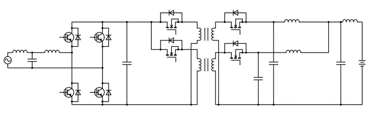
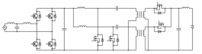
In [22], the authors present a topology identical to [21], only replacing the interleaved isolated Luo converter with interleaved isolated SEPIC converter, as shown in Figure 8b. The charger front-end comprises a full bridge voltage-source converter and the proposed isolated interleaved SEPIC converter makes up the charger back-end. As can be observed, inductors on the input and output side help in suppressing current ripples, especially since this converter operates in discontinuous mode. Just like Singh et al. [21], this converter employs multistep charging for fast and slow charging. Depending on the supply side condition, this charger has vehicle-to-grid (V2G) capability. While this charger can work with minimal impact on supply side power quality, just like [7] this paper lacks data on charging efficiency and charging time. It also has a high component. A similar topology is used in [23], the only difference being that the authors use an isolated interleaved Zeta converter. The Zeta topology, owing to its output inductance, helps achieve continuous output currents, while interleaving further reduces current ripples. Furthermore, this converter topology also supports bidirectional operation. However, a significant drawback of this topology is the high component count of active devices, which may lead to higher switching losses at high frequency operation.
However, a significant concern with respect to interleaved converters is that the designer must pay attention to the current sharing between each parallel converter. This is imperative to ensure even distribution of the current carrying stress on each of the switches. Furthermore, another significant drawback of isolated converters in general stems from the leakage inductance of transformers. This leakage inductance does not allow current to change instantaneously, and during switching operation, this causes a voltage spike across the switch, thus potentially damaging it [24]. To counteract this effect, active or passive clamping circuits should be added with the switch, thus clamping its voltage to a fixed value [24]. However, this may come at the cost of increased component count.
3. Non-Isolated Converters
Owing to the comparatively low charging power required for LEV batteries, researchers have found it feasible to implement non-isolated converter-based charging topologies. One of the key advantages of non-isolated converter-based chargers is that due to the absence of isolation transformer, there is a big reduction in charger module volume. Furthermore, there is an improvement in efficiency and power density [25]. However, a general drawback of non-isolated converters is their low voltage gain range. This issue may be addressed by using switched capacitor or coupled inductor topologies [24][26][27]. Another drawback of non-isolated converters is the lack of galvanic isolation between the battery circuit and supply, which is disadvantageous from a safety standpoint.
In this regard, the authors of [28] have comprehensively reviewed on-board unidirectional chargers, albeit for both short- and long-distance EVs. The authors segregated these chargers into fundamental converter topologies (buck, boost, buck-boost, Cuk, Zeta, SEPIC [29], Luo) and modified converter topologies, in which the aspects of fundamental converters are tweaked to enhance one or more features. Modification techniques for fundamental converters often include interleaving, bridgeless topologies, or both. The consequent effects of these modifications may include, but may not be limited to, reduced ripples in input and output current and improved efficiency.
In non-isolated converters for LEV charging, recent publications have utilized switched inductors to enhance the voltage gain. For example, [30] describes one of the more recent implementations of non-isolated bridgeless LEV chargers. In their work, the authors have presented a single stage bridgeless on-board SEPIC converter-based charger, which uses a switched inductor structure. This charger configuration is shown in Figure 9. As evidenced in the circuit diagram, the identical switched inductors are charged and discharged in series and parallel, respectively—thus helping increase the overall gain of the charger. This converter achieves compact design and reduced component count, owing to absence of transformers. These switches also operate in discontinuous mode, which reduces the switched inductor size. Since a SEPIC topology is used in their work, there is an added advantage of simplified sensing of output voltage since the SEPIC converter delivers a non-inverted output voltage.
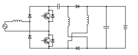
Figure 9. Bridgeless switched inductor SEPIC converter-based topology [30].
The authors of [31] present another charger based on bridgeless non-isolated DC-DC converter with switched inductors. In their work, the authors present a bridgeless Cuk DC-DC converter-based single stage charger, and as in [22], utilize a switch inductor configuration. The only difference is that the switched inductor and diode’s placements are interchanged (much like the fundamental SEPIC and Cuk converter). The converter’s switched inductors are also charged and discharged in series and parallel, respectively. Discontinuous conduction is observed in switches, thus reducing the output inductor size. The component count is also identical to that of [30].
The proposed converters demonstrated satisfactory conversion efficiencies—92.5% for [31] and 93.3% for [30]. This is partly owed to the fact that these two topologies are single stage, thus greatly reducing conduction losses. Furthermore, due to the presence of switched inductors, the single-stage converter helps achieve wider gain range. Additionally, these implementations exhibit minimal impact on the supply current THD, as per IEEE-519 and IEC 61000-3-2 standards. However, there might still be sufficient conduction losses due to a maximum of three diodes providing a conducting path in each positive or negative cycle. Furthermore, due to the use of switched inductors in this circuit, there is also a potential for voltage spikes across switches [32]. This may necessitate the use of voltage clamp circuits alongside the switches.
Sharma et al. [33] present a two-stage non-isolated bidirectional onboard charger LEV. The front-end includes a voltage source converter which converts the AC supply to DC, and controls grid current power quality. The following stage is an interleaved buck-boost converter, which regulates the battery charging current. The bidirectional nature of the given topology makes it suitable for vehicle to grid (V2G) operation. However, this circuit suffers from a high switch count.
Another recent development in non-isolated topologies is the development of quadratic topologies. These topologies have the advantage of achieving high currents at the battery end. Kumar et al. [34] developed a quadratic buck boost converter for LEV charging. This has the advantage of operation at discontinuous conduction, helping to further reduce component size. However, the number of passive components is comparatively high. Additionally, there may be scope for reduction in supply current THD due to DBR front end. This topology is shown in Figure 10.
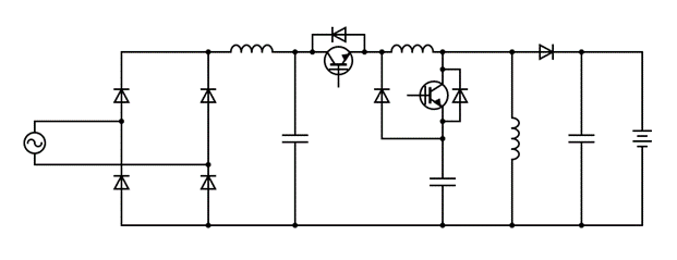
Figure 10. Quadratic buck-boost converter [34].
Finally, [35] presents a detailed review of on-board bidirectional DC-DC converters for EV charging, which also include Level 1 (up to 3.7 kW) and Level 2 (3.7–7 kW) chargers. Their work investigates two-stage and single-stage charger topologies in detail—standards, major components and some converters for PFC and DC-DC stage. The authors emphasize some of the challenges pertaining to single stage on-board chargers: complex control strategy, large output current ripple and sophisticated design. Furthermore, some future trends are highlighted such as advances in topology (use of interleaved converters), semiconductor electronics (wide bandgap devices) and thermal design, to name a few.
A comparison of all the isolated and non-isolated on-board chargers is shown in Table 1.
Table 1. Summary of on-board charger DC-DC converters.
| Isolated Topologies | ||||||||
| Ref. | Topology | Component Count 1 | Salient Features | Areas of Improvement | ||||
| L | C | S | D | Tr. | ||||
| [3] | Isolated Cuk converter + interleaved canonical switching cell (CSC) front-end | 4 | 7 | 3 | 3 | 1 |
|
|
| [4] | Isolated SEPIC converter + diode bridge rectifier front-end | 1 | 3 | 1 | 1 | 1 |
|
|
| [5] | Flyback converter with interleaved Zeta + SEPIC converter front-end | 3 | 4 | 3 | 3 | 1 |
|
|
| [6] | Flyback converter with modified Bridgeless Landsman converter front-end | 4 | 4 | 4 | 5 | 1 |
|
|
| [9] | Bridgeless Isolated Positive Output Luo converter | 2 | 3 | 2 | 3 | 1 |
|
|
| [10] | Bridgeless isolated Zeta converter with PV fed Cuk converter | 4 | 5 | 3 | 4 | 1 |
|
|
| [13] | Half-bridge LLC resonant converter with Cuk converter PFC | 4 | 5 | 3 | 2 | 1 |
|
|
| [14] | Full-bridge LLC resonant converter | 2 | 3 | 4 | 4 | 1 |
|
|
| [15] | Half bridge LLC converter with interleaved buck-boost converter front-end | 5 | 4 | 6 | 2 | 1 |
|
|
| [21] | Interleaved isolated Luo converter with voltage source converter front-end | 3 | 4 | 4 | 0 | 1 |
|
|
| [22] | Interleaved isolated SEPIC converter with voltage source converter front-end | 3 | 4 | 4 | 0 | 1 |
|
|
| [23] | Interleaved isolated Zeta converter with voltage source converter front-end | 2 | 4 | 4 | 0 | 1 |
|
|
| Non-Isolated Topologies | ||||||||
| Ref. | Topology | Component Count 1 | Salient Features | Areas of Improvement | ||||
| L | C | S | D | Tr. | ||||
| [30] | Bridgeless switched inductor SEPIC converter | 3 | 2 | 2 | 4 | NA |
|
|
| [31] | Bridgeless switched inductor Cuk converter | 3 | 2 | 2 | 4 | NA |
|
|
| [33] | Interleaved buck-boost converter with voltage source converter front-end | 2 | 2 | 4 | 0 | NA |
|
|
| [34] | Quadratic buck boost converter with DBR front end | 2 | 3 | 2 | 2 | NA |
|
|
1 Only DC-DC stages are considered; L—inductor; C—Capacitor; S—Active switch; D—Diode; Tr.—Transformer.
References
- Gupta, J.; Kushwaha, R.; Singh, B. Improved Power Quality Transformerless Single-Stage Bridgeless Converter Based Charger for Light Electric Vehicles. IEEE Trans. Power Electron. 2021, 36, 7716–7724.
- Shukla, T.; Kalla, U.K. A Single-Stage positive Cuk Converter based Charging System for Light Electric Vehicle Applications. In Proceedings of the 2021 IEEE 2nd International Conference on Smart Technologies for Power, Energy and Control (STPEC), Bilaspur, India, 19–22 December 2021; pp. 1–6.
- Singh, B.; Gupta, J. Improved Power Quality On-Board Charging Solution for Light Electric Vehicles. In Proceedings of the 2021 IEEE Transportation Electrification Conference & Expo (ITEC), Chicago, IL, USA, 21–25 June 2021; pp. 462–467.
- Gupta, J.; Kushwaha, R.; Singh, B. An Isolated Improved Power Quality Battery Charger for a Light Electric Vehicle. In Proceedings of the 2020 IEEE International Conference on Power Electronics, Smart Grid and Renewable Energy (PESGRE2020), Cochin, India, 2–4 January 2020; pp. 1–6.
- Kushwaha, R.; Singh, B. Power Factor Correction in EV Charger with Bridgeless Zeta-SEPIC Converter. In Proceedings of the 2019 IEEE Energy Conversion Congress and Exposition (ECCE), Baltimore, MD, USA, 29 September–3 October 2019; pp. 121–128.
- Kushwaha, R.; Singh, B. Power Factor Improvement in Modified Bridgeless Landsman Converter Fed EV Battery Charger. IEEE Trans. Veh. Technol. 2019, 68, 3325–3336.
- Kushwaha, R.; Singh, B. Interleaved Landsman Converter Fed EV Battery Charger with Power Factor Correction. IEEE Trans. Ind. Appl. 2020, 56, 4179–4192.
- Gupta, J.; Singh, B. Single-Stage Isolated Bridgeless Charger for Light Electric Vehicle with Improved Power Quality. IEEE Trans. Ind. Appl. 2022, 58, 6357–6367.
- Gupta, J.; Singh, B. Bridgeless Isolated Positive Output Luo Converter Based High Power Factor Single Stage Charging Solution for Light Electric Vehicles. IEEE Trans. Ind. Appl. 2022, 58, 732–741.
- Chaudhary, C.; Mishra, S.; Nangia, U. A Bridgeless Isolated Zeta Converter for Battery Charging Aided with Solar Photovoltaic System. In Proceedings of the 2021 International Conference on Smart Generation Computing, Communication and Networking (SMART GENCON), Pune, India, 29–30 October 2021; pp. 1–6.
- Shukla, T.; Kalla, U.K. A Modified Non-bridged Cuk Converter based Electric Vehicle Charger with Reduced Components Count. In Proceedings of the 2021 IEEE 2nd International Conference on Smart Technologies for Power, Energy and Control (STPEC), Bilaspur, India, 19–22 December 2021; pp. 1–6.
- Sankar, U.A.; Mallik, A.; Khaligh, A. Duty compensated reduced harmonic control for a single-phase H-bridge PFC converter. In Proceedings of the 2018 IEEE Applied Power Electronics Conference and Exposition (APEC), San Antonio, TX, USA, 4–8 March 2018; pp. 1996–2000.
- Pandey, R.; Singh, B. A Cuk Converter and Resonant LLC Converter Based E-Bike Charger for Wide Output Voltage Variations. IEEE Trans. Ind. Appl. 2021, 57, 2682–2691.
- Kim, D.-H.; Kim, M.-S.; Nengroo, S.H.; Kim, C.-H.; Kim, H.-J. LLC Resonant Converter for LEV (Light Electric Vehicle) Fast Chargers. Electronics 2019, 8, 362.
- Dixit, A.; Gangavarapu, S.; Rathore, A.K. High-Efficiency Discontinuous Current-Mode Power Factor Correction-Based Plug-In Battery Charger for Local e-Transportation. IEEE Trans. Transp. Electrif. 2021, 7, 1134–1145.
- Gumera, X.D.; Caberos, A.; Huang, S.-C. Design and Implementation of a High Efficiency Cost Effective EV Charger Using LLC Resonant Converter. In Proceedings of the 2017 Asian Conference on Energy, Power and Transportation Electrification (ACEPT), Singapore, 24–26 October 2017; pp. 1–6.
- Chaurasiya, S.; Singh, B. A High-Power Density Portable Charger for E-Mopeds and E-Rickshaw. In Proceedings of the 2021 IEEE 4th International Conference on Computing, Power and Communication Technologies (GUCON), Kuala Lumpur, Malaysia, 24–26 September 2021; pp. 1–7.
- He, P.; Khaligh, A. Comprehensive Analyses and Comparison of 1 kW Isolated DC–DC Converters for Bidirectional EV Charging Systems. IEEE Trans. Transp. Electrif. 2017, 3, 147–156.
- Shreya, K.; Srivastava, H.; Kumar, P.; Ramanathan, G.; Madhavan, P.; Bharatiraja, C. CUK converter fed resonant LLC converter based electric bike fast charger for efficient cc/cv charging solution. J. Appl. Sci. Eng. 2021, 24, 331–338.
- Syah, M.N.; Firmansyah, E.; Utomo, D.R. Interleaved Bidirectional DC-DC Converter Operation Strategies and Problem Challenges: An Overview. In Proceedings of the 2022 IEEE International Conference in Power Engineering Application (ICPEA), Shah Alam, Malaysia, 7–8 March 2022; pp. 1–6.
- Sharma, U.; Singh, B. A Multistep Bidirectional Onboard Charger for Light Electric Vehicles Using Interleaved Luo Converter. In Proceedings of the 2021 International Conference on Sustainable Energy and Future Electric Transportation (SEFET), Hyderabad, India, 21–23 January 2021; pp. 1–5.
- Sharma, U.; Singh, B. A Bidirectional Onboard Charging System for E-Rickshaw Using Interleaved SEPIC Converter. In Proceedings of the 2020 IEEE 17th India Council International Conference (INDICON), New Delhi, India, 10–13 December 2020; pp. 1–5.
- Sharma, U.; Singh, B. An Onboard Bidirectional Charger for Light Electric Vehicles Using Interleaved ZETA Converter. In Proceedings of the 2020 International Conference on Power, Instrumentation, Control and Computing (PICC), Thrissur, India, 17–19 December 2020; pp. 1–6.
- Lai, C.-M. Development of a Novel Bidirectional DC/DC Converter Topology with High Voltage Conversion Ratio for Electric Vehicles and DC-Microgrids. Energies 2016, 9, 410.
- Wang, J.; Zhang, Y.; Elshaer, M.; Perdikakis, W.; Yao, C.; Zou, K.; Xu, Z.; Chen, C. Nonisolated Electric Vehicle Chargers: Their Current Status and Future Challenges. IEEE Electrif. Mag. 2021, 9, 23–33.
- Sharma, U.; Singh, B. A Bidirectional Charger for Light Electric Vehicle Using Coupled-Inductor based High Gain SEPIC Converter. In Proceedings of the 2021 IEEE 2nd International Conference on Smart Technologies for Power, Energy and Control (STPEC), Bilaspur, India, 19–22 December 2021; pp. 1–6.
- Gupta, J.; Singh, B. A Switched Capacitor-Coupled Inductor Based High Gain Buck Converter with Power Factor Pre-regulator for LEVs Charging Application. In Proceedings of the 2021 IEEE 4th International Conference on Computing, Power and Communication Technologies (GUCON), Kuala Lumpur, Malaysia, 24–26 September 2021; pp. 1–6.
- Sayed, S.S.; Massoud, A.M. Review on State-of-the-Art Unidirectional Non-Isolated Power Factor Correction Converters for Short-/Long-Distance Electric Vehicles. IEEE Access 2022, 10, 11308–11340.
- Blinov, A.; Verbytskyi, I.; Zinchenko, D.; Vinnikov, D.; Galkin, I. Modular Battery Charger for Light Electric Vehicles. Energies 2020, 13, 774.
- Gupta, J.; Kushwaha, R.; Singh, B.; Khadkikar, V. Improved Power Quality Charging System Based on High Step-Down Gain Bridgeless SEPIC APFC for Light Electric Vehicles. IEEE Trans. Ind. Appl. 2022, 58, 423–434.
- Ramanathan, G.; Bharatiraja, C. Design of mono stage bridgeless converter for light electric vehicles charging. Mater. Today Proc. 2022, 52, 1530–1536.
- Hussein, B.; Alsalemi, A.; Ben-Brahim, L. High-Gain Non-isolated Single-Switch DC-DC Converters in Power Factor Correction Rectifiers: A Performance Assessment. In Proceedings of the 2022 3rd International Conference on Smart Grid and Renewable Energy (SGRE), Doha, Qatar, 20–22 March 2022; pp. 1–6.
- Sharma, U.; Singh, B. A Non-isolated Onboard Charger for Electric Vehicle. In Proceedings of the 2021 IEEE Transportation Electrification Conference & Expo (ITEC), Chicago, IL, USA, 21–25 June 2021; pp. 446–451.
- Kumar, A.D.; Gupta, J.; Singh, B. A Single-Stage Charger for LEV Application based on Quadratic Buck-Boost Converter Topology. In Proceedings of the 2022 IEEE IAS Global Conference on Emerging Technologies (GlobConET), Arad, Romania, 20–22 May 2022; pp. 321–326.
- Yuan, J.; Dorn-Gomba, L.; Callegaro, A.D.; Reimers, J.; Emadi, A. A Review of Bidirectional On-Board Chargers for Electric Vehicles. IEEE Access 2021, 9, 51501–51518.
More