This content presents a comprehensive review of protection systems with the penetration of microgrids in the distribution network. The expansion of a microgrid affects the coordination and protection by a change in the current direction in the distribution network.
- Protection System Challenges
- Microgrid
- Protection Schemes
- Wide Area Protection
- Intelligent Algorithms
1. Introduction
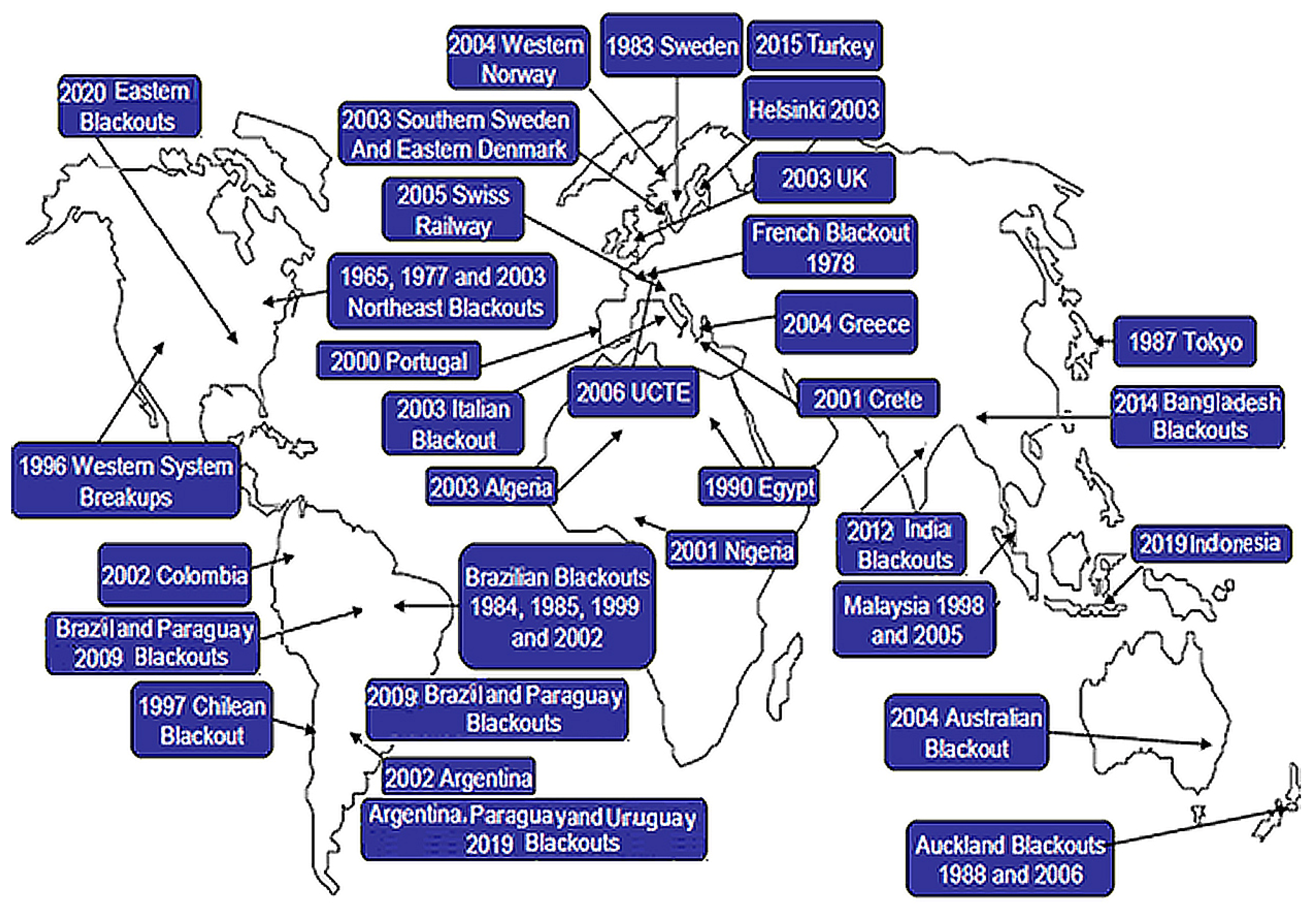
Protection system schemes have increasingly become important due to the increasing complexity and challenges in power systems. The miscoordination and false tripping of protective relays have played a significant role in blackouts and in propagating cascading events [1]. The North American Electric Reliability Council (NERC) has reported that the contribution of protection systems in cascading events is more than 70% [2]. A CIGRÉ [3] study has stated that 27% of bulk power system disturbances result from false trips of tie protection systems. Figure 1 illustrates an update of some major blackouts and disturbances all around the world [3][4][3,4].
The main task of a protection system is to separate the fault section from the healthy part for a stable supply of electrical energy without any interruption, cascading failures, and blackout events. Conventional power system coordination includes the primary and back-up protection [5][6][5,6]. The main parts of the power system (grid), including generation, high voltage transmission line, and distribution, have to be adjusted to appropriate settings. The protection challenges significantly increase with the growth of the power system.
Generation: There are many protective functions and protection schemes in generator protection systems. The authors in References [7][8][7,8] investigated the differences between distance (21) and voltage-controlled or voltage-restraint time-overcurrent (51V) protective relays as the backup protection of a generator. Investigations revealed that the relays 21 and 51V protection functions should not be activated in a zone relay protection system. Depending on the upstream system configuration, both protective relays function 21 or 51V can be used as the generator backup protection. The 21 and 51V protective functions are used as back up protection with, respectively, distance relays and directional overcurrent (DOC) relays in transmission lines.
High voltage transmission lines: Transmission systems are used for delivering electrical energy from generation to customer. There are a lot of faults that occur in the transmission system due to the expansion and long lines. Distance protection is one of the most commonly used ways to protect transmission lines with different zones. Power swing is a significant problem in a protection system, where the impedance seen by the distance relay oscillates due to the swings in the voltage and current in the transmission line. When power swing goes into the operating zone, the relay may unnecessarily trip [9]. The issues of the transmission system with parallel lines increase due to the mutual coupling, back-feed, in-feed, and poor discrimination between the faulty and healthy lines. These issues affect the distance protection especially in the case of fault occurrence near the far end bus [10][11][10,11]. Several solutions have been proposed to solve the problems of parallel lines protection [12][13][14][12,13,14]. The authors of References [12][13][12,13] proposed methods to protect parallel transmission lines using wavelet transform by employing its magnificent characteristics to detect the disturbances in the current signals and to estimate the phasors of all signals as well as to achieve high-speed relaying. In Reference [14], the authors proposed an adaptive distance protection based on the information surrounding the protected line under different operating conditions. The impact of flexible AC transmission system (FACTS) on protective devices, such as distance relays, in the transmission line has been shown. The FACTS devices in transmission lines enhance the power transfer capability of the line, while causing serious problems for distance protection of transmission lines [15][16][15,16]. The transformer inrush current influences protective relays. The inrush currents lead to the maloperation of transformer differential relays [17][18][17,18]. The early solution to avoid the maloperation of differential relays is to delay the relay operation [19]. Reference [20] presented a differential relay with only harmonic restraint for bus protection. Modern transformer differential relays use either harmonic restraint or blocking methods [21]. These methods ensure relay security for a very high percentage of inrush and over-excitation cases. The method is not useful with very low harmonic content in the operating current.
Distribution system: In recent years, the structure of distribution networks has changed with the diversification of consumers and technological breakthroughs. Therefore, protection issues of distribution networks have increased. High impedance fault (HIF) is one of the challenges in a distribution network. High impedance faults in distribution feeders cause abnormal electrical conditions that cannot be detected by a typical protection system because of low fault current and high impedance at the fault point [22]. Moreover, failing to detect an HIF may cause fire hazards and risk to human life [23][24][25][23,24,25]. Various solutions have been presented to detect HIFs. Chakraborty and Das [23] presented an HIF detection method with several even harmonics existing in voltage waveforms. The authors of Reference [24] used a method with a systematic design of feature extraction based on the HIF detection and classification method. A discrete wavelet transform has been proposed for HIF detection along with frequency range and RMS conversion to implement a pattern recognition-based detection algorithm [26].
2. Microgrid
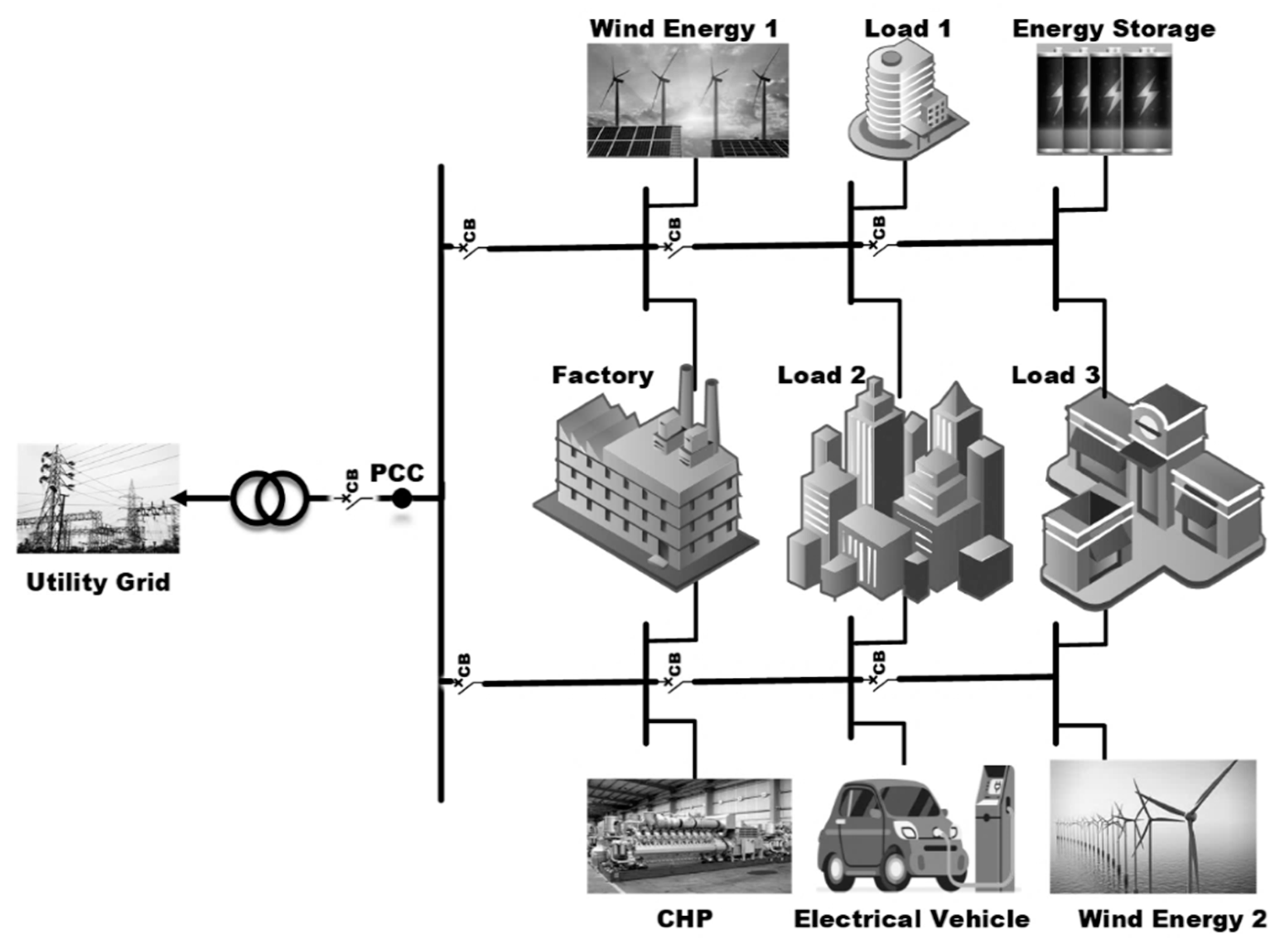
A set of interconnected loads and DGs within clearly defined electrical boundaries that act as a single controllable entity can be operated in both grid-connected and islanded modes [27][28]. The increase in the cost of energy delivery from power plants to consumers and the need for improving system reliability and environmental benefits justify the movement towards DG technologies [28][29]. In existing protection methods, a microgrid can cause many challenges in terms of the protection of blinding zones, false tripping of protective relays, decreasing fault levels, islanding, and auto-reclosers [29][30][31][30,31,32]. Figure 2 depicts a typical model of a microgrid that is connected to the grid at the point of common coupling (PCC).
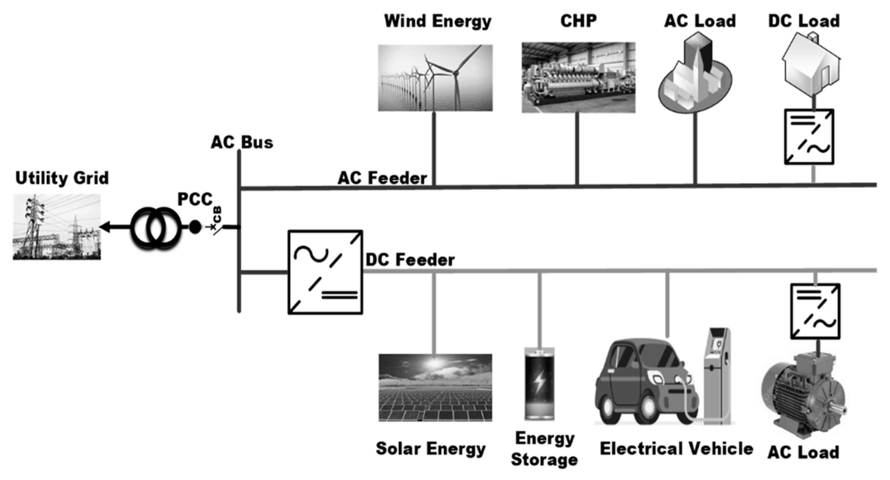
Microgrids are very diverse concerning their connection, protection, communication, DC/AC system, type of DG, etc. The authors of Reference [32][33] divided microgrids into three types with different operation modes including facility microgrids, remote microgrids, and utility microgrids. Facility microgrids operate in intentional or unintentional islanded mode, remote microgrids only include the islanded mode and utility microgrids operate in grid-connected mode. Additionally, facility and utility microgrids have utility connections modes contrary to remote microgrids. Remote microgrids are mainly used in distant areas, islands, and large geographically spans. The authors of Reference [33][34] investigated two types of DGs, i.e., a typical rotating synchronous machine and an inverter-based DG. The main reason for this classification is the difference between the short circuit current level and AC/DC voltage. A remote microgrid spans a larger geographical area compared to facility and utility microgrids. The authors of Reference [34][35] classified microgrids into three main categories depending on the connection to AC or DC buses, i.e., a microgrid can be AC, DC, or hybrid AC/DC. These researchers addressed the advantages and disadvantages of AC and DC systems. Most power system components, such as loads and transmission lines, work with AC systems. The authors of Reference [35][36] compared the fault current characteristics of AC and DC distribution systems in the presence of DGs. They investigated the differences among the protection schemes in AC/DC systems and found that the AC short circuit current has a sinusoidal waveform with two zero-crossing in each period including a fault impedance value and a high-raising-rate current. In Reference [34][35], the disadvantages of AC systems are presented in terms of DGs synchronization, power quality, and three-phase unbalance. Some of the advantages of DC systems are higher efficiency, no power factor losses, and low voltage level as well as no need for inverters and transformer. In addition, the nature of DC power facilitates exploiting renewable resources and supplying DC loads. A hybrid microgrid facilitates the direct integration of both AC- and DC-based DGs in the same distribution network. Reference [36][37] has proposed a fault analysis method based on a simplified model of AC/DC hybrid microgrid system. The method used a mathematical model equivalent simplification for the analysis of the characteristic system under fault conditions. Figure 3 shows a hybrid structure with both AC and DC microgrids.
A smart grid provides an optimal way of distributing electricity from various sources of generation plants and DGs. The goals of employing a smart grid in the power system are as follows:
- involving individuals as an integral part of the power system, consumers or electricity providers;
- using more renewable energy;
- decreasing the dependency on electricity generation from power plants;
- decreasing complete blackouts;
- boosting the power system capacity to supply electricity;
- reducing the time to restore the power system after fault occurrence;
- peak shaving [37].
- involving individuals as an integral part of the power system, consumers or electricity providers;
- using more renewable energy;
- decreasing the dependency on electricity generation from power plants;
- decreasing complete blackouts;
- boosting the power system capacity to supply electricity;
- reducing the time to restore the power system after fault occurrence;
- peak shaving [38].
There have been several discussions on the protection of microgrids, each of them has focused on different issues. In Reference [35][36], the authors present a detailed technical overview of microgrids and smart grids in light of present developments and future trends. They described the functions of smart grid components that include smart device interface components, advanced forecasting, control of generation/storage units, data transmission/monitoring, power flow, and energy management. Reference [36][37] analyzed the fault current characteristics in AC and DC distribution systems, first, then it describes the protection methods for AC and DC systems, and, finally, it compares the protection methods in AC and DC networks. Reference [38][39] presented a review on issues and approaches for microgrid protection. This reference focused on microgrid control including centralized and decentralized controls. Reference [39][40] reviewed the adaptive protection methods for microgrids. It presented different methodologies of adaptive protection systems with microgrids. A review on the protection schemes and coordination techniques in microgrid systems on presented in Reference [40][41].