Your browser does not fully support modern features. Please upgrade for a smoother experience.
Please note this is a comparison between Version 1 by Shahid Hussain and Version 4 by Jessie Wu.
Optimization in electrical machine design refers to the process of making improvements to the design of an electrical machine in order to maximize its performance and/or cost-effectiveness. To examine and optimize several aspects of the machine, including various parameters such as the shape of the machine, mathematical models and algorithms are often used.
- additive manufacturing
- topology optimization
- level set
- flux
1. Introduction
Generally, optimization techniques can be classified as deterministic and stochastic optimization. Deterministic optimization techniques, such as gradient-based methods, use a specific mathematical formula to find the optimal solution. They are fast and reliable but may be trapped in a local minimum while stochastic optimization techniques, such as genetic algorithms and particle swarm optimization use random processes to explore the solution space. They are less likely to get trapped in a local minimum but may be slower and less reliable [1][60]. The choice of method depends on the specific problem and requirements of the application.
Moreover, commonly used machine geometry templates and mathematical models for optimization are used to shape magnetic structures in electrical machines. These methods are well established and have been used for many years in the design and optimization of electrical machines. The use of these methods can make the design process more efficient and manageable, but it also restricts the design options to the predefined parameters, limiting the possible shapes and forms that can be generated. On the other hand, topology optimization (TO) is a more recent technique that involves the optimization of the overall layout and structure of the magnetic components in an electrical machine, rather than just the shape of individual components. For example, in the design of electrical machines, flux barriers inside the rotor or stator design spaces can be added and optimized for performance improvement. If the geometry optimization is utilized for the flux barriers, it increases the optimization variables and is not flexible to get the optimal shape [2][3][4][5][61,62,63,64]. Nevertheless, the TO approach can lead to more efficient and lightweight designs, but it is generally more computationally intensive and requires specialized software [6][7][8][65,66,67]. The integration of TO and AM is demonstrated in the flowchart depicted in Figure 1.
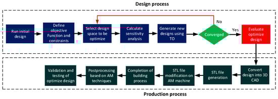
Figure 1.
Steps involved for the TO and AM integration.
2. Topology Optimization of Reluctance Machines
The main objective of most TO studies for electric machines is to improve torque density and optimize the torque profile or cogging torque by adjusting the material distribution in the rotor. This can be achieved by using advanced optimization techniques and algorithms to find the optimal distribution of material in the rotor that results in the highest torque density or the desired torque profile [9][13]. Additionally, reluctance machines such as synchronous reluctance and switch reluctance machines have a simple construction compared to other types of electric machines, which makes them a good candidate for TO [9][10][11][12][13][13,68,69,70,71]. Despite receiving less attention, the TO of electric machine stator design has been reported in [14][15][72,73]. Different TO methods have been developed in the field of electrical machines during the last few years and these techniques may be broadly categorized into three groups: (i) the ON–OFF method, (ii) the Level set method, and (iii) the Material density method.
2.1. ON–OFF Method
The ON–OFF-based TO technique divides the design space into smaller cells and assigns each cell as either air (OFF) or iron (ON) through a discretization process using triangular or rectangular mesh structure [16][74]. This technique can be combined with various numerical optimization methods, such as evolutionary and gradient-based algorithms, to find approximate optimal solutions. In [17][18][19][20][75,76,77,78], evolutionary-based methods that do not require gradient information have been used. However, it may result in complex and non-intuitive shapes with isolated or disconnected regions of material, as shown in Figure 2a. This can lead to difficulties in fabrication or reduced performance of the final design. To overcome this issue, the author in [21][22][23][24][79,80,81,82] proposed the ON–OFF method with an immune algorithm to optimize the rotor of SRM, in which the filtering process is introduced to obtain the feasible shapes and improve the torque property as shown in Figure 2b.
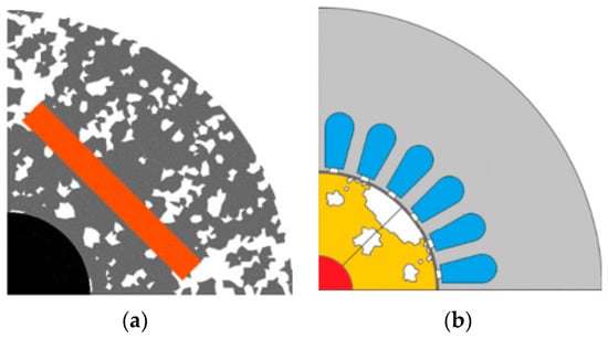
Figure 2.
ON–OFF TO results: (
a
) without filter; (
b
) with filter using immune algorithm.
In [5][25][64,83], ON–OFF-based normalized Gaussian network (NGNet) is presented to improve the torque density and reduce the iron losses. The output of the NGNet is determined by:
where Gi�� is the Gaussian function, wi�� and bi�� are the weight coefficient and normalized function, respectively. N� represents the number of Gaussian functions and i, j is the number of cells. The state of the cells can be determined by:
Se={on y(xe)≥0off y(xe)<0��={�� �(��)≥0��� �(��)<0
The material is configured to iron when the cell is in the on state, whereas it is configured to air when the cell is in the off state. Three different optimization problems were studied to improve the performance of the machine: (i) maximize torque; (ii) minimize iron losses with constraint of average torque; (iii) maximize average torque with constraint of iron losses. Furthermore, the Gaussian function distribution and the optimized design is shown in Figure 3a. There should be a tradeoff between the average torque and the iron losses because the wider rotor surface increases the torque, but also, the latter should be made smaller to reduce the iron losses. Another filtering technique, Gabor filter combined with ON–OFF method based on NGNet, is presented in [26][84]. The authors concluded that the proposed filter provided lower torque ripples as compared to the conventional NGNet, and the optimized design using filter gives the thinner flux barriers as depicted in Figure 3b. The main disadvantage of the abovementioned methods is the high computational cost because the FEA computation is needed at each generation [27][85].
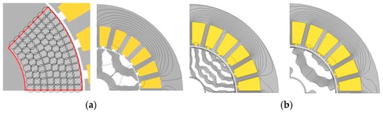
Figure 3.
(
a
) Gaussian function distribution and optimized resulted shape; (
The gradient based ON–OFF TO solves the problem of high computational cost but has the probability that it may stop on a local optimal solution. In [28][86], the gradient-based TO are applied to a 6/14 SRM to enhance the dynamic torque of the machine. The stator tooth is selected for the design space of the TO, then utilizes the method of adjoint gradients with respect to the material properties to optimize the material distribution for the reduction of torque ripples. The main drawback of this method is the difficulty in the evaluation of the non-differentiable functions [5][64].
2.2. Level Set Method
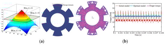
The level set method uses an implicit function known as the “level set function” to handle interfaces and shapes numerically. The level set method was first introduced in [29][87] for the purpose of using it in TO to represent material boundaries. They demonstrated that this method can be used to design a cantilever beam with distinct boundaries without being dependent on a mesh or grayscale elements. Furthermore, the level set technique, which is based on gradients, produces a solution that is more practical for the given problem but lower convergence rate. In the level set TO, the material boundaries are shown in Figure 4a and computationally it can be defined as [30][88]:
φ(x,t)=⎧⎩⎨⎪⎪φ(x,t)>0φ(x,t)=0φ(x,t)<0ferromagnetic materialboundary edgeAir�(�,�)={�(�,�)>0������������� ���������(�,�)=0�������� �����(�,�)<0���
The objective of level set topology optimization is to find the optimal distribution of material in a design space to meet specific design objectives, by determining the value of φ(x,t)�(�,�) at each location (x,t)(�,�). In [31][89], the rotor of the synchronous reluctance machine was optimized using the level set method combined with the continuum sensitivity analysis. The objective function of the problem was to improve the torque of the machine by redistributing the magnetic material throughout the rotor design. The torque ripples profile of 8/6 pole SRM is enhanced by using the level set method, and sensitivity analysis having the adjoint variable method is utilized in [32][90]. In the optimized design, the average torque is improved by 12% with also the reduction in the torque ripples. The initial and optimized model with the torque waveform comparison is shown in Figure 4b. For reducing the iron losses and improving the torque of the synchronous reluctance machine, the level set method with sensitivity analysis of adjoint variable method is employed [33][91].
Additionally, this technique does not need the creation of intermediary materials or rely on the mesh that is used to discretize the design domain [34][92]. The level set approach for TO of EM devices has become quite well-liked as a result of these benefits [35][93]. However, this approach has certain limitations, including the need for an initial definition for the level set representation, convergence to local optima, and difficulties in computing the form gradients necessary to develop the interface [36][94].
2.3. Material Density Method
The density method is a technique that was originally developed for solid mechanics TO [37][14]. It is a simple method that has recently gained popularity for electromagnetic TO, even for multi-material problems. This method is based on the idea of using a density function to represent the material distribution in the design domain, then using optimization algorithms to find the optimal density distribution that satisfies certain design constraints and objectives. This method has been found to be effective for a wide range of electromagnetic optimization problems and has been applied to a variety of different types of electromagnetic structures [12][15][38][39][40][41][70,73,95,96,97,98]. It is based on interpolation, filtering, and projection schemes, and originally used the simple power-law as the material penalization function. This leads to the SIMP (Solid Isotropic Material with Penalization) approach [42][99]. A schematic flowchart of procedures in the material density method is presented in Figure 5.
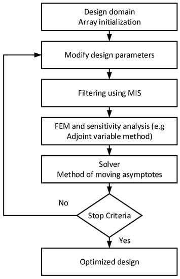
Figure 5.
Flowchart of the TO using the material density-based method.
By solving the magnetic flux density and integrating the Maxwell tensor stress using (5) to determine torque, the material density approach is used to optimize the 8/6 pole rotor of the SRM [43][100].
T=∬ dAr×(S.n)�=∬ ���×(�.�)
The objective of the optimization problem is to determine the function density and is defined as:
where Ωm�� and Ωa�� represents the ferromagnetic region and air region, respectively. In the material density method, the ρ(x)�(�) gives the values between 0 and 1 but practically, the distribution of the material is either 0 or 1, due to which the discontinuity exists in the final shape. To make the material distribution feasible, the magnetic reluctivity is defined by the smooth heaviside function [44][101]:
where hℎ represents the one half of the transition width between ρ(−h)=0�(−ℎ)=0 and ρ(h)=1�(ℎ)=1. The magnetic reluctivity is defined as:
where vF(∣∣B2∣∣)��(|�2|) is the magnetic reluctivity and is a function of the mgnetic flux density and vi��, vair���� is the reluctivity of the ith��ℎ element and reluctivity of air, respectively. The penalization coefficient is represented by the variable p.�. By choosing the proper value of p�, the gray elements can be eliminated. In [45][102], the material density-based TO was utilized for the torque ripple minimization and the design space include the stator teeth and rotor poles. The optimized design showed a significant amount of reduction in the profile of torque ripple with the cost of a slight reduction of 7.22% in the average torque. In addition, the initial and optimized design of 6/4 pole SRM is depicted in Figure 6a. The TO of material density was applied in [46][103] to minimize the torque ripple and the final design reach to the target torque value. The design space includes the half of the rotor pole as shown in Figure 6b, and after optimization, the torque reached the target value. The overview of TO applied to the reluctance machine for performance enhancement is shown in Table 1.
ρ(x)={1 xϵΩm0 xϵΩa�(�)={1 ����0 ����
ρ(ψ)=316(ψh)5−58(ψh)3+316(ψh)+12 (−h≤ψ≤h)�(�)=316(�ℎ)5−58(�ℎ)3+316(�ℎ)+12 (−ℎ≤�≤ℎ)
vi(ψi, ∣∣B2∣∣)=(1−ρ(ψi))p∗vair+(ρ(ψi))p×vF(∣∣B2∣∣)��(��, |�2|)=(1−�(��))�∗����+(�(��))�×��(|�2|)
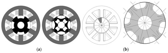
Figure 6.
(
a
) Initial and optimized design of 6/4 SRM; (
b
) Initial design geometry and optimized design.
Table 1.
Summary of TO used in reluctance machines for performance improvement.
| Machine Type | Optimization Method | Design Space | Objective Function | Prototype Fabrication |
Reference |
|---|---|---|---|---|---|
| SRM | Material density method | Stator teeth and rotor poles | Min. torque ripples | Yes | [44][101] |
| SRM | Level set method | Rotor poles | Max. average torque and min. torque ripples | No | [31][89] |
| SynRM | Level set method | The rotor | Max. average torque | No | [30][88] |
| SynRM | ON-OFF | The rotor | Max. torque | No | [4][63] |
| SRM | NGNet | Stator teeth | Min. iron losses | No | [27][85] |
| SRM | Gradient based ON-OFF | The rotor | Min. torque ripples | No | [42][99] |
| SRM | Material density + GCMMA | The rotor | Max. torque | No | [45][102] |
| SynRM | Material density + GCMMA | The rotor | Max. torque | No | [25][83] |
| SRM | ON-OFF NGNet | The rotor | Max. torque | No | [20][78] |
| SynRM | Using Gabor filter | The rotor | Min. torque ripples | No | [16][74] |